EP1083718A2 - Mehrträgerempfänger mit auswählbaren Demodulatoren - Google Patents
Mehrträgerempfänger mit auswählbaren Demodulatoren Download PDFInfo
- Publication number
- EP1083718A2 EP1083718A2 EP00119285A EP00119285A EP1083718A2 EP 1083718 A2 EP1083718 A2 EP 1083718A2 EP 00119285 A EP00119285 A EP 00119285A EP 00119285 A EP00119285 A EP 00119285A EP 1083718 A2 EP1083718 A2 EP 1083718A2
- Authority
- EP
- European Patent Office
- Prior art keywords
- signal
- fft
- demodulator
- ofdm
- processing
- Prior art date
- Legal status (The legal status is an assumption and is not a legal conclusion. Google has not performed a legal analysis and makes no representation as to the accuracy of the status listed.)
- Granted
Links
Images


Classifications
-
- H—ELECTRICITY
- H04—ELECTRIC COMMUNICATION TECHNIQUE
- H04L—TRANSMISSION OF DIGITAL INFORMATION, e.g. TELEGRAPHIC COMMUNICATION
- H04L27/00—Modulated-carrier systems
- H04L27/26—Systems using multi-frequency codes
- H04L27/2601—Multicarrier modulation systems
- H04L27/2647—Arrangements specific to the receiver only
- H04L27/2649—Demodulators
- H04L27/265—Fourier transform demodulators, e.g. fast Fourier transform [FFT] or discrete Fourier transform [DFT] demodulators
-
- H—ELECTRICITY
- H04—ELECTRIC COMMUNICATION TECHNIQUE
- H04L—TRANSMISSION OF DIGITAL INFORMATION, e.g. TELEGRAPHIC COMMUNICATION
- H04L27/00—Modulated-carrier systems
- H04L27/18—Phase-modulated carrier systems, i.e. using phase-shift keying
- H04L27/20—Modulator circuits; Transmitter circuits
- H04L27/2032—Modulator circuits; Transmitter circuits for discrete phase modulation, e.g. in which the phase of the carrier is modulated in a nominally instantaneous manner
- H04L27/2053—Modulator circuits; Transmitter circuits for discrete phase modulation, e.g. in which the phase of the carrier is modulated in a nominally instantaneous manner using more than one carrier, e.g. carriers with different phases
- H04L27/206—Modulator circuits; Transmitter circuits for discrete phase modulation, e.g. in which the phase of the carrier is modulated in a nominally instantaneous manner using more than one carrier, e.g. carriers with different phases using a pair of orthogonal carriers, e.g. quadrature carriers
-
- H—ELECTRICITY
- H04—ELECTRIC COMMUNICATION TECHNIQUE
- H04L—TRANSMISSION OF DIGITAL INFORMATION, e.g. TELEGRAPHIC COMMUNICATION
- H04L27/00—Modulated-carrier systems
- H04L27/26—Systems using multi-frequency codes
- H04L27/2601—Multicarrier modulation systems
- H04L27/2626—Arrangements specific to the transmitter only
- H04L27/2627—Modulators
- H04L27/2628—Inverse Fourier transform modulators, e.g. inverse fast Fourier transform [IFFT] or inverse discrete Fourier transform [IDFT] modulators
-
- H—ELECTRICITY
- H04—ELECTRIC COMMUNICATION TECHNIQUE
- H04L—TRANSMISSION OF DIGITAL INFORMATION, e.g. TELEGRAPHIC COMMUNICATION
- H04L27/00—Modulated-carrier systems
- H04L27/26—Systems using multi-frequency codes
- H04L27/2601—Multicarrier modulation systems
- H04L27/2647—Arrangements specific to the receiver only
- H04L27/2655—Synchronisation arrangements
Definitions
- the present invention relates to a communication apparatus based on an OFDM (Orthogonal Frequency Division Multiplexing) system.
- OFDM Orthogonal Frequency Division Multiplexing
- a conventional OFDM-based communication apparatus generally uses coherent detection or delay detection as a demodulation system.
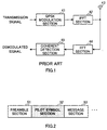
- a conventional OFDM communication apparatus that carries out coherent detection will be explained with reference to FIG.1.
- FIG.1 is a block diagram showing a configuration of a conventional OFDM communication apparatus that carries out coherent detection.
- a transmission signal is subjected to QPSK modulation processing for every subcarrier by QPSK modulation section 41.
- the transmission signal subjected to QPSK modulation is subjected to IFFT (inverse Fourier transform) processing and thereby frequency-division multiplexed by IFFT section 42.
- the transmission signal subjected to IFFT processing is transmitted via antenna 43.
- the signal transmitted via antenna 43 has a frame configuration as shown in FIG.2.
- FIG.2 is a schematic diagram showing a frame format used for the conventional OFDM communication apparatus. As shown in FIG.2, the signal transmitted via antenna 43 is configured by preamble section 51, pilot symbol section 52 and message section 53 in an old-to-new time sequence. Each signal with this frame configuration is sent carried on one packet.
- the signal sent from the other end of communication is received via antenna 43.
- the other end of communication above has the same configuration as that shown in FIG.1 and the signal sent from this other end of communication is subjected to the same processing as that in the transmission system described above.
- the signal received via antenna 43 is subjected to FFT (Fourier transform) processing by FFT section 44.
- FFT Fast Fourier transform
- a signal carried by each subcarrier is extracted.
- the signal extracted by FFT section 44 is subjected to coherent detection processing by coherent detection section 45. In this way, a demodulated signal is extracted.
- FIG.3 is a block diagram showing an internal configuration of coherent detection section 45 in the conventional OFDM transmission apparatus that carries out coherent detection.
- Coherent detection section 45 performs transmission path estimation using a pilot symbol in the reception signal and performs coherent detection processing by carrying out transmission path compensation on the reception signal using the transmission path estimation information obtained.
- reception signal (RX1) is sent to complex multiplication section 62, level detection section 63 and multiplication section 65 via switching section 61.
- This reception signal (RX1) is the signal extracted from FFT section 44 shown in FIG.1.
- reception signal (RX1) is expressed in the following expression: where, R1 is an amplitude variation due to fading, etc. and ⁇ 1 is a phase variation due to fading, etc. and TX is a signal transmitted from the other end of communication (transmission signal).
- the signal in the pilot section of the reception signal expressed in expression 1 ⁇ above, that is, the reception signal (RXP1) in the pilot section is expressed in the following expression: where, Pilot is a pilot symbol.
- Complex multiplication section 62 estimates a transmission path characteristic by carrying out complex multiplication processing using the reception signal (RX1) and pilot symbol (Pilot). That is, a transmission path characteristic (Profile1) as shown in the following expression is obtained by multiplying the reception signal (RXP1) in the pilot symbol section expressed in expression 2 ⁇ above by a conjugate complex number (Pilot*) of the pilot symbol (Pilot).
- Profile1 a transmission path characteristic as shown in the following expression is obtained by multiplying the reception signal (RXP1) in the pilot symbol section expressed in expression 2 ⁇ above by a conjugate complex number (Pilot*) of the pilot symbol (Pilot).
- the transmission path characteristic (Profile1) obtained is sent to division section 64.
- level detection section 63 calculates reception power of the reception signal (RX1).
- the reception power of the reception signal (RX1) is R1 2 from expression 1 ⁇ above.
- the reception power of the reception signal (RX1) is sent to division section 64.
- Division section 64 performs the following division processing using the transmission path characteristic (Profile1) from complex multiplication section 62 and the reception power from level detection section 63.
- Profile1 transmission path characteristic
- the result of the division processing in division section 64 is sent to multiplication section 65.
- Multiplication section 65 performs transmission path compensation on the reception signal using the result of the division processing in division section 64. That is, a demodulated signal is obtained by multiplying the reception signal (RX1) from switching section 61 by the conjugate complex number in expression 5 ⁇ above as shown in the following expression:
- FIG.4 is a block diagram showing a configuration of an OFDM communication apparatus that carries out delay detection.
- the OFDM communication apparatus shown in FIG.4 has a configuration including DQPSK modulation section 71 and delay detection section 72 instead of QPSK modulation section 41 and coherent detection section 45 in FIG.1.
- As a frame format the one shown in FIG.2 can be used.
- DQPSK modulation section 71 performs differential coding QPSK modulation (generally referred to as "DQPSK modulation") on the transmission signal.
- Delay detection section 72 performs delay detection processing on the reception signal (RX1) by multiplying the signal at the current time by the signal preceding by 1 OFDM symbol. Through this multiplication processing, a demodulated signal is obtained.
- the conventional OFDM communication apparatus above has problems as shown below. That is, in the conventional OFDM communication apparatus that carries out coherent detection, when the communication speed of one packet is slower than the channel variation speed, the channel condition at the time of reception of the pilot symbol section in each packet differs from the channel condition at the time of reception of the message section of the packet above. Thus, transmission path compensation is performed on the message section above using the transmission path characteristic estimated by the pilot symbol section above, and therefore the error rate characteristic of the demodulated signal obtained in the message section above deteriorates a great deal.
- the conventional OFDM communication apparatus that carries out delay detection outputs the result of multiplying the signal at the current time by the signal preceding by 1 OFDM symbol as a demodulated signal, and therefore an error caused by a transmission path variation included in this demodulated signal is only 1 OFDM symbol.
- the communication speed of one packet is slower than the channel variation speed, deterioration of the error rate characteristic of the demodulated signal is small.
- the noise component superimposed on the demodulated signal doubles by multiplying the signal at the current time by the signal preceding by 1 OFDM symbol, and therefore if the communication speed of one packet is sufficiently faster than the channel variation speed, the error rate characteristic of the demodulated signal deteriorates compared to the conventional OFDM communication apparatus that carries out coherent detection.
- the error rate characteristic of the demodulated signal may deteriorate depending on the relationship between the communication speed of one packet and channel variation speed.
- This object is attained by the reception system performing demodulation processing on the reception signal according to factors that influence the quality of the demodulated signal. Furthermore, this object is attained by the transmission system performing modulation processing on the transmission signal according to the demodulation processing carried out by the other end of communication.
- FIG.6 is a block diagram showing a configuration of an OFDM communication apparatus according to Embodiment 1 of the present invention.
- a transmission signal is sent to QPSK modulation section 101 and DQPSK modulation section 102.
- QPSK modulation section 101 performs QPSK modulation on the transmission signal above for every subcarrier.
- the QPSK-modulated transmission signal is output to selection section 103.
- DQPSK modulation section 102 performs DQPSK modulation on the transmission signal above.
- the DQPSK-modulated transmission signal is output to selection section 103.
- Selection section 103 receives, as an input, a control signal from timing generation section 110 as to which signal should be output to IFFT section 104, the signal from QPSK modulation section 101 or the signal from DQPSK modulation section 102. That is, when the communication speed of one packet is sufficiently faster than the channel variation speed, timing generation section 110 outputs to selection section 103 a control signal instructing that the signal from QPSK modulation section 101 should be output to IFFT section 104. On the contrary, when the communication speed of one packet is slower than the channel variation speed, timing generation section 110 outputs a control signal instructing that the signal from DQPSK modulation section 102 should be output to IFFT section 104.
- the communication speed of one packet refers to a speed when the apparatus on the transmitting side transmits one packet and the apparatus on the receiving side completes the reception of this packet.
- the relationship between the channel variation speed used in timing generation section 110 and communication speed of one packet can be decided from, for example, the quality (error rate characteristic, etc.) of a demodulated signal output from selection section 109 of the reception system, which will be described later.
- Selection section 103 outputs either the signal from QPSK modulation section 101 or the signal from DQPSK modulation section 102 to IFFT section 104 based on the control signal from timing generation section 110.
- IFFT section 104 performs IFFT processing on the signal sent from selection section 103. In this way, the signal sent from selection section 103 is frequency-division multiplexed and sent to the other end of communication via antenna 105.
- the frame configuration of the signal sent via antenna 105 is as shown in FIG.2 referred to previously. Each signal with the frame configuration shown in FIG.2 is sent carried on one packet.
- the signal sent from the other end of communication is received via antenna 105.
- the other end of communication has the same configuration as that shown in FIG.6 and the signal sent from this other end of communication is subjected to the same processing as that in the transmission system described above.
- the signal received via antenna 105 is subjected to FFT processing by FFT section 106. In this way, the signal sent through each subcarrier is extracted and output to coherent detection section 107 and delay detection section 108.
- Coherent detection section 107 performs coherent detection processing on the signal extracted by FFT section 106 and extracts a demodulated signal.
- Delay detection section 108 performs delay detection processing on the signal extracted by FFT section 106 and extracts a demodulated signal. Both the demodulated signal extracted from coherent detection section 107 and demodulated signal extracted from delay detection section 108 are output to selection section 109.
- Selection section 109 receives, as an input, a control signal from timing generation section 110 as to which signal should be output as the demodulated signal, the signal from coherent detection section 107 or the signal from delay detection section 108. More specifically, when the communication speed of one packet is sufficiently faster than the channel variation speed (when a QPSK-modulated signal from the other end of communication via antenna 105 is received via antenna 105), timing generation section 110 outputs a control signal instructing that a signal from coherent detection section 107 should be output to IFFT section 104 as the demodulated signal.
- timing generation section 110 outputs a control signal instructing that a signal from delay detection section 108 should be output as the demodulated signal.
- Selection section 109 outputs either the signal from coherent detection section 107 or signal from delay detection section 108 as the demodulated signal based on the control signal from timing generation section 110. In this way, when the communication speed of one packet is sufficiently faster than the channel variation speed, the reception signal is subjected to coherent detection processing and a demodulated signal is extracted. On the contrary, when the communication speed of one packet is slower than the channel variation speed, the reception signal is subjected to delay detection processing and a demodulated signal is extracted.
- the reception system performs demodulation processing of either coherent detection processing or delay detection processing on the reception signal according to whether the communication speed of one packet is faster or slower than the channel variation speed, that is, the relationship between the communication speed of one packet and the channel variation speed.
- the transmission system performs modulation processing (QPSK modulation or DQPSK modulation) corresponding to the demodulation processing carried out by the other end of communication on the transmission signal, and therefore the other end of communication above can reliably suppress deterioration of the error rate characteristic of the demodulates signal.
- This embodiment describes the case where the reception system uses two kinds of demodulation system, coherent detection and delay detection, while the transmission system uses two kinds of modulation system, QPSK modulation and DQPSK modulation, but the present invention is not limited to this and is also applicable when both reception system and transmission system use 3 or more types of demodulation system and modulation system, respectively.
- this embodiment describes the case where a relationship between the communication speed of one packet and channel variation speed is used as the selection criteria of the demodulation system for the reception system and modulation system for the transmission system.
- the present invention is not limited to this, and it is also applicable to cases where simply the communication speed of one packet (length of one packet), channel variation speed or various factors that have influence on the quality of a demodulated signal (error rate characteristic, etc.) in the reception system are used as the selection criteria.
- Embodiment 2 provides a mode of further reducing the scale of hardware by configuring the coherent detection section and delay detection section in Embodiment 1 with a single circuit.
- the OFDM communication apparatus according to this embodiment will be explained with reference to FIG.7 and FIG.8 below.
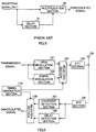
- FIG.7 is a block diagram showing a configuration of the OFDM communication apparatus according to Embodiment 2 of the present invention.
- FIG.8 is a block diagram showing an internal configuration of the demodulation section of the OFDM communication apparatus according to Embodiment 2 of the present invention.
- the parts in FIG.7 with the same configuration as that in Embodiment 1 (FIG.6) are assigned the same reference numerals as those in FIG.6 and their detailed explanations will be omitted.
- timing generation section 202 when a QPSK-modulated signal is received from the other end of communication via antenna 105, timing generation section 202 outputs a control signal instructing that the signal extracted from FFT section 106 should be subjected to coherent detection processing to demodulation section 201.
- timing generation section 202 When a DQPSK-modulated signal is received from the other end of communication via antenna 105, timing generation section 202 outputs a control signal instructing that the signal extracted from FFT section 106 should be subjected to delay detection processing to demodulation section 201.
- Demodulation section 201 carries out demodulation processing of either coherent detection processing or delay detection processing on the signal extracted by FFT section 106 based on the control signal from timing generation section 202. That is, when the communication speed of one packet is sufficiently faster than the channel variation speed, demodulation section 201 performs coherent detection processing on the signal extracted by FFT section 106, and on the contrary, when the communication speed of one packet is slower than the channel variation speed, demodulation section 201 performs delay detection processing on the signal extracted by FFT section 106.
- a reception signal (RX) is sent via switching section 301 to complex multiplication section 302, level detection section 303 and multiplication section 305.
- This reception signal (RX) is the signal extracted by FFT section 106 shown in FIG.7.
- Complex multiplication section 302 performs complex multiplication processing using the reception signal (RX) and a pilot symbol (Pilot) to estimate a transmission path characteristic.
- the estimated transmission path characteristic is sent to division section 304.
- level detection section 303 calculates the reception power of the reception signal (RX). This reception power is sent to division section 304.
- Division section 304 carries out division processing using the transmission path characteristic from complex multiplication section 302 and reception power from level detection section 303. The result of this division processing is sent to selection section 307.
- delay section 306 delays the reception signal (RX) by 1 OFDM symbol and then sends the reception signal to selection section 307.
- Selection section 307 selects either the signal from delay section 306 or the signal from division section 304 as the output signal to multiplication section 305 based on the control information from timing generation section 202. That is, when the control signal from timing generation section 202 is a control signal instructing that coherent detection processing should be carried out, selection section 307 selects the signal from division section 304 as the output signal to multiplication section 305. On the contrary, when the control signal from timing generation section 202 is a control signal instructing that delay detection processing should be carried out, selection section 307 selects the signal from delay section 306 as the output signal to multiplication section 305.
- Multiplication section 305 multiplies the reception signal (RX) by the signal selected by selection section 307.
- the control signal from timing generation section 202 is a control signal instructing that coherent detection processing should be carried out
- transmission path compensation for the reception signal is carried out using the estimated transmission path estimation information.
- the control signal from timing generation section 202 is a control signal instructing that delay detection processing should be carried out
- multiplication processing is carried out between the signal at the current time and the signal 1 OFDM symbol ahead and thereby delay detection processing is carried out on the reception signal (RX).
- Embodiment 1 it is possible to further reduce the scale of hardware compared to Embodiment 1 by configuring the coherent detection section and delay detection section with a single circuit.
- the OFDM communication apparatus can be mounted on a communication terminal apparatus or base station apparatus in a digital mobile communication system.
- the present invention performs demodulation processing according to factors that influence the quality of a demodulated signal, and therefore can provide an OFDM communication apparatus that suppresses deterioration of the error rate characteristic of the demodulated signal.
Landscapes
- Engineering & Computer Science (AREA)
- Signal Processing (AREA)
- Computer Networks & Wireless Communication (AREA)
- Mathematical Physics (AREA)
- Physics & Mathematics (AREA)
- General Physics & Mathematics (AREA)
- Discrete Mathematics (AREA)
- Digital Transmission Methods That Use Modulated Carrier Waves (AREA)
- Mobile Radio Communication Systems (AREA)
- Detection And Prevention Of Errors In Transmission (AREA)
- Synchronisation In Digital Transmission Systems (AREA)
- Circuits Of Receivers In General (AREA)
- Radio Transmission System (AREA)
Applications Claiming Priority (2)
| Application Number | Priority Date | Filing Date | Title |
|---|---|---|---|
| JP25363399 | 1999-09-07 | ||
| JP25363399A JP3796076B2 (ja) | 1999-09-07 | 1999-09-07 | Ofdm通信装置 |
Publications (3)
| Publication Number | Publication Date |
|---|---|
| EP1083718A2 true EP1083718A2 (de) | 2001-03-14 |
| EP1083718A3 EP1083718A3 (de) | 2005-06-29 |
| EP1083718B1 EP1083718B1 (de) | 2009-02-25 |
Family
ID=17254066
Family Applications (1)
| Application Number | Title | Priority Date | Filing Date |
|---|---|---|---|
| EP00119285A Expired - Lifetime EP1083718B1 (de) | 1999-09-07 | 2000-09-06 | Mehrträgerempfänger mit auswählbaren Demodulatoren |
Country Status (6)
| Country | Link |
|---|---|
| US (1) | US6868056B1 (de) |
| EP (1) | EP1083718B1 (de) |
| JP (1) | JP3796076B2 (de) |
| KR (1) | KR100345422B1 (de) |
| CN (1) | CN1281009C (de) |
| DE (1) | DE60041618D1 (de) |
Cited By (1)
| Publication number | Priority date | Publication date | Assignee | Title |
|---|---|---|---|---|
| US7095797B2 (en) | 2001-08-17 | 2006-08-22 | Matsushita Electric Industrial Co., Ltd. | Method of modulating a data signal with modulation switching between direct and differential modulation and apparatus for modulation |
Families Citing this family (10)
| Publication number | Priority date | Publication date | Assignee | Title |
|---|---|---|---|---|
| FR2813474B1 (fr) * | 2000-08-28 | 2002-12-13 | Commissariat Energie Atomique | Procede de reception non coherente dp-mok avec combinaison de trajets multiples et recepteur correspondant |
| WO2004040832A1 (ja) * | 2002-10-31 | 2004-05-13 | Matsushita Electric Industrial Co., Ltd. | 送信装置及び送信方法 |
| JP2004215225A (ja) | 2002-12-17 | 2004-07-29 | Sony Corp | 通信システムおよび通信方法、並びにデータ処理装置 |
| JP4618494B2 (ja) * | 2002-12-17 | 2011-01-26 | ソニー株式会社 | 通信装置および通信方法 |
| US7321614B2 (en) * | 2003-08-08 | 2008-01-22 | Intel Corporation | Apparatus and methods for communicating using symbol-modulated subcarriers |
| US7394858B2 (en) * | 2003-08-08 | 2008-07-01 | Intel Corporation | Systems and methods for adaptive bit loading in a multiple antenna orthogonal frequency division multiplexed communication system |
| US7349436B2 (en) * | 2003-09-30 | 2008-03-25 | Intel Corporation | Systems and methods for high-throughput wideband wireless local area network communications |
| EP1542488A1 (de) * | 2003-12-12 | 2005-06-15 | Telefonaktiebolaget LM Ericsson (publ) | Verfahren un vorrichtung zur Zuweisung von Kanaladaptierten Pilotsignalen |
| US20060075923A1 (en) * | 2004-10-12 | 2006-04-13 | Richardson H W | Method of manufacture and treatment of wood with injectable particulate iron oxide |
| JP2007067567A (ja) * | 2005-08-29 | 2007-03-15 | Mitsubishi Electric Corp | 通信装置、送信装置および受信装置 |
Family Cites Families (24)
| Publication number | Priority date | Publication date | Assignee | Title |
|---|---|---|---|---|
| US4290140A (en) * | 1978-02-23 | 1981-09-15 | Northrop Corporation | Combined coherent frequency and phase shift keying modulation system |
| US5862192A (en) * | 1991-12-31 | 1999-01-19 | Lucent Technologies Inc. | Methods and apparatus for equalization and decoding of digital communications channels using antenna diversity |
| WO1993018593A1 (en) * | 1992-03-02 | 1993-09-16 | Motorola Inc. | Clock recovery method and apparatus in a diversity receiver |
| AU1052895A (en) * | 1993-11-09 | 1995-05-29 | Pacific Communication Sciences, Inc. | Method and apparatus for dual demodulation of mobile channel signals |
| JP3455621B2 (ja) * | 1995-07-04 | 2003-10-14 | シャープ株式会社 | 通信装置 |
| JP3575883B2 (ja) * | 1995-09-18 | 2004-10-13 | 三菱電機株式会社 | ディジタル復調器 |
| JP3288574B2 (ja) * | 1996-02-26 | 2002-06-04 | 松下電器産業株式会社 | データ受信装置 |
| US5862132A (en) * | 1996-04-22 | 1999-01-19 | Motorola, Inc. | System and method for multiple access short message communications |
| JPH09307526A (ja) * | 1996-05-17 | 1997-11-28 | Mitsubishi Electric Corp | デジタル放送受信機 |
| US5764690A (en) * | 1996-06-04 | 1998-06-09 | Motorola, Inc. | Apparatus for despreading and demodulating a burst CDMA signal |
| JPH1075274A (ja) * | 1996-08-29 | 1998-03-17 | Mitsubishi Electric Corp | 軟判定復号器 |
| JP3286189B2 (ja) * | 1996-11-14 | 2002-05-27 | 松下電器産業株式会社 | アルゴリズムダイバーシチを用いた受信装置 |
| JP3373746B2 (ja) * | 1997-01-07 | 2003-02-04 | 株式会社鷹山 | Ds−cdma基地局間非同期セルラ方式における初期同期方法および受信機 |
| JP3565537B2 (ja) * | 1997-06-18 | 2004-09-15 | 株式会社日立国際電気 | 直交周波数分割多重変調信号の伝送方式 |
| JP3360205B2 (ja) * | 1997-10-23 | 2002-12-24 | 富士通株式会社 | Cdma受信装置 |
| JP3097634B2 (ja) * | 1997-11-07 | 2000-10-10 | 日本電信電話株式会社 | Ofdm変復調回路 |
| US6295311B1 (en) * | 1997-11-07 | 2001-09-25 | Hughes Electronics Corporation | Method and apparatus for compensating for phase differences in received signals |
| JP3335570B2 (ja) * | 1997-11-17 | 2002-10-21 | 沖電気工業株式会社 | スペクトラム拡散通信装置 |
| JP3724940B2 (ja) * | 1998-01-08 | 2005-12-07 | 株式会社東芝 | Ofdmダイバーシチ受信装置 |
| JPH11215091A (ja) * | 1998-01-22 | 1999-08-06 | Toshiba Corp | Ofdm信号伝送方法及びofdm信号伝送装置 |
| JP3900670B2 (ja) * | 1998-04-17 | 2007-04-04 | ソニー株式会社 | 通信装置 |
| JP3741866B2 (ja) * | 1998-06-05 | 2006-02-01 | 富士通株式会社 | 適応変調方式 |
| US6654340B1 (en) * | 1999-03-31 | 2003-11-25 | Cisco Technology, Inc. | Differential OFDM using multiple receiver antennas |
| US6594320B1 (en) * | 1999-08-25 | 2003-07-15 | Lucent Technologies, Inc. | Orthogonal Frequency Division Multiplexed (OFDM) carrier acquisition method |
-
1999
- 1999-09-07 JP JP25363399A patent/JP3796076B2/ja not_active Expired - Fee Related
-
2000
- 2000-08-09 US US09/635,096 patent/US6868056B1/en not_active Expired - Lifetime
- 2000-09-06 KR KR1020000052621A patent/KR100345422B1/ko not_active Expired - Lifetime
- 2000-09-06 DE DE60041618T patent/DE60041618D1/de not_active Expired - Lifetime
- 2000-09-06 CN CNB001268392A patent/CN1281009C/zh not_active Expired - Lifetime
- 2000-09-06 EP EP00119285A patent/EP1083718B1/de not_active Expired - Lifetime
Cited By (1)
| Publication number | Priority date | Publication date | Assignee | Title |
|---|---|---|---|---|
| US7095797B2 (en) | 2001-08-17 | 2006-08-22 | Matsushita Electric Industrial Co., Ltd. | Method of modulating a data signal with modulation switching between direct and differential modulation and apparatus for modulation |
Also Published As
| Publication number | Publication date |
|---|---|
| JP2001077790A (ja) | 2001-03-23 |
| EP1083718B1 (de) | 2009-02-25 |
| CN1287421A (zh) | 2001-03-14 |
| KR20010050345A (ko) | 2001-06-15 |
| JP3796076B2 (ja) | 2006-07-12 |
| EP1083718A3 (de) | 2005-06-29 |
| KR100345422B1 (ko) | 2002-07-26 |
| DE60041618D1 (de) | 2009-04-09 |
| US6868056B1 (en) | 2005-03-15 |
| CN1281009C (zh) | 2006-10-18 |
Similar Documents
| Publication | Publication Date | Title |
|---|---|---|
| US11283659B2 (en) | Communication device | |
| US7463577B2 (en) | OFDM communication method and OFDM communication device | |
| EP2264934B1 (de) | Digitales Funkübertragungssystem und Verfahren mit adaptiver Modulation | |
| KR100341189B1 (ko) | 송수신 장치 및 변조 방식 추정 방법 | |
| US8787496B2 (en) | Receiving method and apparatus, and communication system using the same | |
| EP1133093A1 (de) | Ofdm nachrichtenübertragungsvorrichtung und detektionsverfahren | |
| EP1073241A2 (de) | Synchronisieren von Symbolen bei Mehrträgerübertragung | |
| US6871046B2 (en) | Radio transmitting apparatus and radio transmitting method | |
| US6868056B1 (en) | Apparatus and method for OFDM communication | |
| US20060034385A1 (en) | Wireless communication apparatus and method for estimating number of antennas | |
| JP2001196981A (ja) | 歪み推定装置 | |
| JP4255908B2 (ja) | マルチキャリア信号復調回路およびマルチキャリア信号復調方法 | |
| JP3678930B2 (ja) | Ofdm送信装置及びofdm送信方法 |
Legal Events
| Date | Code | Title | Description |
|---|---|---|---|
| PUAI | Public reference made under article 153(3) epc to a published international application that has entered the european phase |
Free format text: ORIGINAL CODE: 0009012 |
|
| AK | Designated contracting states |
Kind code of ref document: A2 Designated state(s): AT BE CH CY DE DK ES FI FR GB GR IE IT LI LU MC NL PT SE |
|
| AX | Request for extension of the european patent |
Free format text: AL;LT;LV;MK;RO;SI |
|
| PUAL | Search report despatched |
Free format text: ORIGINAL CODE: 0009013 |
|
| RIC1 | Information provided on ipc code assigned before grant |
Ipc: 7H 04L 27/233 B Ipc: 7H 04L 27/227 B Ipc: 7H 04L 27/26 A |
|
| AK | Designated contracting states |
Kind code of ref document: A3 Designated state(s): AT BE CH CY DE DK ES FI FR GB GR IE IT LI LU MC NL PT SE |
|
| AX | Request for extension of the european patent |
Extension state: AL LT LV MK RO SI |
|
| 17P | Request for examination filed |
Effective date: 20050825 |
|
| AKX | Designation fees paid |
Designated state(s): DE FR GB SE |
|
| 17Q | First examination report despatched |
Effective date: 20060206 |
|
| GRAP | Despatch of communication of intention to grant a patent |
Free format text: ORIGINAL CODE: EPIDOSNIGR1 |
|
| RAP1 | Party data changed (applicant data changed or rights of an application transferred) |
Owner name: PANASONIC CORPORATION |
|
| GRAS | Grant fee paid |
Free format text: ORIGINAL CODE: EPIDOSNIGR3 |
|
| GRAA | (expected) grant |
Free format text: ORIGINAL CODE: 0009210 |
|
| AK | Designated contracting states |
Kind code of ref document: B1 Designated state(s): DE FR GB SE |
|
| REG | Reference to a national code |
Ref country code: GB Ref legal event code: FG4D |
|
| REF | Corresponds to: |
Ref document number: 60041618 Country of ref document: DE Date of ref document: 20090409 Kind code of ref document: P |
|
| REG | Reference to a national code |
Ref country code: SE Ref legal event code: TRGR |
|
| PLBE | No opposition filed within time limit |
Free format text: ORIGINAL CODE: 0009261 |
|
| STAA | Information on the status of an ep patent application or granted ep patent |
Free format text: STATUS: NO OPPOSITION FILED WITHIN TIME LIMIT |
|
| 26N | No opposition filed |
Effective date: 20091126 |
|
| REG | Reference to a national code |
Ref country code: GB Ref legal event code: 732E Free format text: REGISTERED BETWEEN 20140925 AND 20141001 |
|
| REG | Reference to a national code |
Ref country code: DE Ref legal event code: R082 Ref document number: 60041618 Country of ref document: DE Representative=s name: EISENFUEHR SPEISER PATENTANWAELTE RECHTSANWAEL, DE |
|
| REG | Reference to a national code |
Ref country code: DE Ref legal event code: R082 Ref document number: 60041618 Country of ref document: DE Representative=s name: EISENFUEHR SPEISER PATENTANWAELTE RECHTSANWAEL, DE Effective date: 20150109 Ref country code: DE Ref legal event code: R081 Ref document number: 60041618 Country of ref document: DE Owner name: INVENTERGY, INC. (N.D.GES.D. STAATES DELAWARE), US Free format text: FORMER OWNER: PANASONIC CORPORATION, KADOMA-SHI, OSAKA, JP Effective date: 20150109 Ref country code: DE Ref legal event code: R081 Ref document number: 60041618 Country of ref document: DE Owner name: INVT SPE LLC (N.D.GES.D. STAATES DELAWARE), SA, US Free format text: FORMER OWNER: PANASONIC CORPORATION, KADOMA-SHI, OSAKA, JP Effective date: 20150109 |
|
| REG | Reference to a national code |
Ref country code: GB Ref legal event code: 732E Free format text: REGISTERED BETWEEN 20150129 AND 20150204 |
|
| REG | Reference to a national code |
Ref country code: FR Ref legal event code: PLFP Year of fee payment: 16 |
|
| REG | Reference to a national code |
Ref country code: FR Ref legal event code: TP Owner name: INVENTERGY, INC., US Effective date: 20151027 |
|
| REG | Reference to a national code |
Ref country code: FR Ref legal event code: PLFP Year of fee payment: 17 |
|
| REG | Reference to a national code |
Ref country code: FR Ref legal event code: PLFP Year of fee payment: 18 |
|
| REG | Reference to a national code |
Ref country code: DE Ref legal event code: R082 Ref document number: 60041618 Country of ref document: DE Representative=s name: EISENFUEHR SPEISER PATENTANWAELTE RECHTSANWAEL, DE Ref country code: DE Ref legal event code: R081 Ref document number: 60041618 Country of ref document: DE Owner name: INVT SPE LLC (N.D.GES.D. STAATES DELAWARE), SA, US Free format text: FORMER OWNER: INVENTERGY, INC. (N.D.GES.D. STAATES DELAWARE), CAMPBELL, CALIF., US |
|
| PGFP | Annual fee paid to national office [announced via postgrant information from national office to epo] |
Ref country code: SE Payment date: 20170912 Year of fee payment: 18 |
|
| REG | Reference to a national code |
Ref country code: GB Ref legal event code: 732E Free format text: REGISTERED BETWEEN 20171214 AND 20171222 |
|
| REG | Reference to a national code |
Ref country code: FR Ref legal event code: TP Owner name: INVT SPE LLC, US Effective date: 20171018 |
|
| REG | Reference to a national code |
Ref country code: FR Ref legal event code: PLFP Year of fee payment: 19 |
|
| REG | Reference to a national code |
Ref country code: SE Ref legal event code: EUG |
|
| PG25 | Lapsed in a contracting state [announced via postgrant information from national office to epo] |
Ref country code: SE Free format text: LAPSE BECAUSE OF NON-PAYMENT OF DUE FEES Effective date: 20180907 |
|
| PGFP | Annual fee paid to national office [announced via postgrant information from national office to epo] |
Ref country code: DE Payment date: 20190827 Year of fee payment: 20 Ref country code: FR Payment date: 20190815 Year of fee payment: 20 |
|
| PGFP | Annual fee paid to national office [announced via postgrant information from national office to epo] |
Ref country code: GB Payment date: 20190905 Year of fee payment: 20 |
|
| REG | Reference to a national code |
Ref country code: DE Ref legal event code: R071 Ref document number: 60041618 Country of ref document: DE |
|
| REG | Reference to a national code |
Ref country code: GB Ref legal event code: PE20 Expiry date: 20200905 |
|
| PG25 | Lapsed in a contracting state [announced via postgrant information from national office to epo] |
Ref country code: GB Free format text: LAPSE BECAUSE OF EXPIRATION OF PROTECTION Effective date: 20200905 |