EP1083091B1 - Ablagefach für einen Behälter insbesondere in einem Kraftwagen - Google Patents
Ablagefach für einen Behälter insbesondere in einem Kraftwagen Download PDFInfo
- Publication number
- EP1083091B1 EP1083091B1 EP00116580A EP00116580A EP1083091B1 EP 1083091 B1 EP1083091 B1 EP 1083091B1 EP 00116580 A EP00116580 A EP 00116580A EP 00116580 A EP00116580 A EP 00116580A EP 1083091 B1 EP1083091 B1 EP 1083091B1
- Authority
- EP
- European Patent Office
- Prior art keywords
- storage compartment
- wall
- container
- horizontal position
- approximately
- Prior art date
- Legal status (The legal status is an assumption and is not a legal conclusion. Google has not performed a legal analysis and makes no representation as to the accuracy of the status listed.)
- Expired - Lifetime
Links
- 239000002689 soil Substances 0.000 description 4
- 210000001331 nose Anatomy 0.000 description 3
- 230000005489 elastic deformation Effects 0.000 description 2
- 230000006378 damage Effects 0.000 description 1
- 230000001419 dependent effect Effects 0.000 description 1
- 230000005484 gravity Effects 0.000 description 1
- 238000002347 injection Methods 0.000 description 1
- 239000007924 injection Substances 0.000 description 1
- 238000004091 panning Methods 0.000 description 1
Images


Classifications
-
- B—PERFORMING OPERATIONS; TRANSPORTING
- B60—VEHICLES IN GENERAL
- B60R—VEHICLES, VEHICLE FITTINGS, OR VEHICLE PARTS, NOT OTHERWISE PROVIDED FOR
- B60R7/00—Stowing or holding appliances inside vehicle primarily intended for personal property smaller than suit-cases, e.g. travelling articles, or maps
- B60R7/04—Stowing or holding appliances inside vehicle primarily intended for personal property smaller than suit-cases, e.g. travelling articles, or maps in driver or passenger space, e.g. using racks
Definitions
- the invention relates to a storage compartment for a container, in particular in a motor vehicle with the features of the preamble of claim 1.
- the storage compartment is in particular intended for attachment to an inside of a side wall of the container, the container, for example, under a center armrest in the car can be accommodated.
- the storage compartment is for example for the storage of Small parts provided in the larger container.
- a storage compartment for a container wherein the Storage compartment is attachable to an inner side of a side wall of the container, the Storage compartment has a bottom, which by means of a pivot joint from a roughly horizontal in an approximately vertical position is pivotally, the storage compartment a Wall which is pivotally mounted by means of a pivot joint on the ground and can be pivoted from a voltage applied to the ground in a projecting position from the ground.
- the invention is based on the object, the storage space to save space in the larger To accommodate containers.
- the Storage compartment according to the invention is to the inside of the side wall of the container to the storage compartment is attached, pivoting, so that the storage compartment when not in use only takes up little space.
- the storage compartment according to the invention a floor which, with a swivel joint from an approximately horizontal, from the side wall in the container projecting position in an approximately vertical, on the inside of the side wall of the container adjacent position is pivotable. at Not in use, the bottom is pivoted to the side wall of the container, so that the entire volume of the container is available as storage space.
- a wall of the storage compartment pivotally mounted, which from a protruding from the ground into a lying on the ground Position is pivotable.
- the wall When not in use the storage compartment, the wall is in Plant pivoted to the ground and the ground in its approximately vertical standing position.
- the storage compartment according to the invention has a drive mechanism (Gear) on, the pivoting movements of the wall and bottom of the storage compartment inevitably coordinated with each other, so that when panning the soil of the in approximately vertical in the approximately horizontal position, the wall of the storage compartment from the on Ground adjacent pivoted in the projecting position from the ground. Will the Floor pivoted from the approximately horizontal in the approximately vertical position, pivoted the drive mechanism the wall from the floor projecting into the on the ground adjoining position.
- the invention has the advantage that it has a subdivision possibility a container offers, and that they have a proper storage of small parts in a larger container, the inventive Storage compartment when not in use saves space on the inside of a side wall of the Container is housed.
- the drive mechanism has a cam mechanism on.
- the cam gear has a stationary guideway in a plane perpendicular to a pivot axis of the floor.
- the guideway runs arcuately in changing distance around the pivot axis of the Soil.
- the wall of the storage compartment has a guide element, for example a laterally projecting guide pin, which engages in the guideway.
- Cam mechanism is an angular position of the wall to the bottom of the storage compartment dependent from the swivel angle of the floor, the pivotal movement of the wall becomes inevitable derived from the pivotal movement of the soil, so that the wall protrudes from the ground, when this assumes its approximately horizontal position, and so that the wall rests on the ground when it assumes its approximately vertical position.
- the bottom of the storage compartment has a Overload protection, which supports the ground in the approximately horizontal position. Becomes The storage compartment is overloaded, for example, by a heavy object on the storage compartment is put on, gives the overload protection, so that the ground after can fold down below. As a result, destruction of the storage compartment is avoided.
- the bottom of the storage compartment is resilient in the in about horizontal position and pressed the wall in the protruding from the ground position.
- a releasable holding device in the in held approximately vertical position.
- the releasable holding device can, for example, a Snap nose, which is elastically pushed aside when the bottom of the is pressed in about vertical position in the direction of the horizontal position. After Overcome the holding device pivots the bottom spring loaded in his about vertical position.
- push-push or heart cam locking devices can be used as a releasable holding device use.
- inventive storage compartment 10th basically has a main body 12, a bottom 14 and a wall 16, which are manufactured as plastic injection molded parts.
- the main body 12 has a Longitudinal wall 18, projecting from the two ends end walls 20.
- the bottom 14 is about a pivot joint 90 ° from a vertical, parallel to the base plate 12 Position in a horizontal, at right angles from the base plate 12 projecting position pivotable. In the horizontal position, the bottom 14 is located at lower edges the end walls 20.
- the pivot joint is formed by two pins 22 through Holes 24 inserted in the end walls 20 of the base 12 in holes 26 of the bottom 14 are.
- the two pins 22 are close to the longitudinal wall 18 and close above the lower Ranges of the end walls 20 arranged, they define a parallel to the longitudinal wall 18 Pivot axis of the bottom 14.
- Torsionsschraubenfedern 28th attached, which, as shown in Figures 2-4 recognizable, supported on the base 12 and the Press bottom 14 in the horizontal position.
- the bottom 14 has laterally projecting ribs 30, which in the vertical position of Floor with snap tabs 32 on the mutually facing inner sides of the end walls 20 cooperate and form a releasable holding device 30, 32.
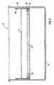
- the ribs 30 In the horizontal Position of the bottom 14 are the ribs 30 on support strips 34 (see. Figure 5), which are also arranged on the inner sides of the end walls 20 and the together with the ribs 30 form an overload protection 30, 34 of the storage compartment 10.
- the wall 16 is pivotable by 90 ° from a voltage applied to the bottom 14 in one of the Floor 14 protruding position pivotally connected to the bottom 14.
- a pivot joint on which is formed by two pins 36 passing through holes 38 in tabs on end faces the wall 16 in holes 40 in the bottom 14 are inserted.
- a torsion coil spring 42 is placed on the pins 36. The torsion coil spring 42 is supported on Floor 14 and presses the wall 16 in the protruding from the bottom 14 position.
- the storage compartment 10 according to the invention can be inserted into a box-shaped container 44, in a side wall a recess 46 for receiving the longitudinal wall 18th of the base part 12 of the storage compartment 10 has.
- guideways 48 are provided which as Grooves are formed and the arched (not necessarily arcuate) around the Holes 24 extend around which define the pivot axis of the bottom 14.
- the wall 16 laterally projecting pins 50 which form guide elements and in the guideways 48 intervene.
- the fixed guideways 48 and the pins 50 form a Cam mechanism 48, 50 for the pivotally connected to the bottom 14 wall 16.
- FIG. 2 shows the storage compartment inserted into the container 44 10 in a position of use.
- the longitudinal wall 18 on the base body 12 of the storage compartment 10 is mounted on the inside of a side wall 52 of the container 44.
- the bottom 14 is perpendicular and horizontal from the side wall 52 of the container 44 into the interior of the container 44 off.
- the bottom 14 lies with its lateral ribs 30 on the dump bars 34 of the end walls 20 of the storage compartment 10, wherein the torsion coil springs 28th Press the bottom 14 in support on the support strips 34.
- the pivoting with the Floor 14 connected wall 16 is vertically upwards from the bottom 14. she will pressed by the torsion coil springs 42 in this position and the pins 50, which engage in the guideways 48, held in this position.
- the storage compartment 10 is not needed, it may be in the non-use position shown in FIG be spent.
- the bottom 14 against the force of the torsion coil springs 28 is pushed upward in the vertical position shown in Figure 3.
- the wall 16 In the vertical position there is a gap between the bottom 14 and the longitudinal wall 18, in which the wall 16 rests.
- the guideways 48 and the pins 50 form a cam gear 48, 50, the wall 16 during pivoting the bottom 14 is forcibly pivoted in abutment against the bottom 14. If the bottom 14 is pivoted back to the horizontal position, cause the guideways 48 and the pins 50 a forced pivoting of the wall 16 in the perpendicular from the bottom 14 upstanding position.
- the wall 16 or the bottom 14 of the storage compartment 10 in the use position for example overloaded by placing a heavy object over the ribs 30 of the bottom 14 by elastic deformation of the support strips 34 of the End walls 20 and the bottom 14 pivoted together with the wall 16 as shown in FIG 4 shown beyond the horizontal position down.
- the ribs 30 of the soil 14 form together with the support strips 34 of the end walls 20 an overload protection, the folding away of the bottom 14 together with the wall 16 down at Allow overloading.
- the bottom 14 is pushed upwards, until his ribs 30 have overcome the Auflagerangn 34 and the storage compartment 10 is ready for use again.
Landscapes
- Engineering & Computer Science (AREA)
- Mechanical Engineering (AREA)
- Vehicle Step Arrangements And Article Storage (AREA)
- Details Of Rigid Or Semi-Rigid Containers (AREA)
Description
- Figur 1
- ein erfindungsgemäßes Ablagefach perspektivisch in Explosionsdarstellung;
- Figur 2
- einen Querschnitt durch das Ablagefach aus Figur 1;
- Figur 3
- einen Querschnitt gemäß Figur 2 bei Nichtgebrauch des Ablagefachs;
- Figur 4
- einen Querschnitt gemäß Figur 2 bei Überbelastung des Ablagefachs; und
- Figur 5
- einen Längsschnitt durch das Ablagefach aus Figur 1.
Claims (6)
- Ablagefach für einen Behälter insbesondere in einem Kraftwagen, wobei das Ablagefach an einer Innenseite einer Seitenwand des Behälters anbringbar ist, das Ablagefach (10) einen Boden (14) aufweist, der mittels eines Schwenkgelenks (22) aus einer in etwa horizontalen in eine in etwa vertikale Stellung schwenkbar ist, und das Ablagefach (10) eine Wand (16) aufweist, die mittels eines Schwenkgelenks (36) schwenkbar am Boden (14) angebracht ist und aus einer am Boden (14) anliegenden in eine vom Boden (14) abstehende Stellung schwenkbar ist, dadurch gekennzeichnet dass das Ablagefach (10) einen Antriebsmechanismus (48, 50) aufweist, der beim Schwenken des Bodens (14) aus der in etwa vertikalen in die in etwa horizontale Stellung die Wand (16) aus der am Boden (14) anliegenden in die vom Boden (14) abstehende Stellung und umgekehrt verschwenkt.
- Ablagefach nach Anspruch 1, dadurch gekennzeichnet, dass der Antriebsmechanismus ein Kurvengetriebe (48, 50) aufweist.
- Ablagefach nach Anspruch 2, dadurch gekennzeichnet, dass das Kurvengetriebe (48, 50) eine ortsfeste Führungsbahn (48) in einer zu einer Schwenkachse des Bodens (14) senkrechten Ebene aufweist, die bogenförmig und in sich änderndem Abstand um die Schwenkachse des Bodens (14) verläuft, und dass die Wand (16) des Ablagefachs (10) ein Führungselement (50) aufweist, welches mit Abstand von der Schwenkachse der Wand (16) angeordnet ist und mit der Führungsbahn (48) verschieblich in Eingriff steht.
- Ablagefach nach Anspruch 1, dadurch gekennzeichnet, dass der Boden (14) eine Überlastsicherung (30, 34) aufweist, die den Boden (14) in der in etwa horizontalen Stellung abstützt und die bei Überbelastung des Bodens (14) den Boden (14) nach unten wegklappen lässt.
- Ablagefach nach Anspruch 1, dadurch gekennzeichnet, dass das Ablagefach (10) ein Federelement (28), welches den Boden (14) in die in etwa horizontale Stellung drückt, und eine lösbare Halteeinrichtung (30, 32), die den Boden (14) gegen die Kraft des Federelements (28) in der in etwa vertikalen Stellung hält, aufweist.
- Ablagefach nach Anspruch 1, dadurch gekennzeichnet, dass das Ablagefach (10) ein Federelement (42) aufweist, welches die Wand (16) in die vom Boden (14) abstehende Stellung drückt.
Applications Claiming Priority (2)
| Application Number | Priority Date | Filing Date | Title |
|---|---|---|---|
| DE19942629 | 1999-09-07 | ||
| DE19942629A DE19942629A1 (de) | 1999-09-07 | 1999-09-07 | Ablagefach für einen Behälter insbesondere in einem Kraftwagen |
Publications (3)
| Publication Number | Publication Date |
|---|---|
| EP1083091A2 EP1083091A2 (de) | 2001-03-14 |
| EP1083091A3 EP1083091A3 (de) | 2001-06-13 |
| EP1083091B1 true EP1083091B1 (de) | 2003-04-09 |
Family
ID=7921065
Family Applications (1)
| Application Number | Title | Priority Date | Filing Date |
|---|---|---|---|
| EP00116580A Expired - Lifetime EP1083091B1 (de) | 1999-09-07 | 2000-08-01 | Ablagefach für einen Behälter insbesondere in einem Kraftwagen |
Country Status (7)
| Country | Link |
|---|---|
| US (1) | US6427605B1 (de) |
| EP (1) | EP1083091B1 (de) |
| JP (1) | JP3377507B2 (de) |
| KR (1) | KR20010030118A (de) |
| AT (1) | ATE236808T1 (de) |
| DE (2) | DE19942629A1 (de) |
| ES (1) | ES2194655T3 (de) |
Families Citing this family (8)
| Publication number | Priority date | Publication date | Assignee | Title |
|---|---|---|---|---|
| EP1605237A1 (de) | 2004-06-05 | 2005-12-14 | Trumpf Werkzeugmaschinen GmbH + Co. KG | Laserbearbeitungsmaschine mit Strahldiagnosevorrichtung sowie entsprechendes Verfahren zur Bestimmung wenigstens eines Strahlkenndatums eines Laserstrahls |
| WO2012000676A1 (de) | 2010-06-30 | 2012-01-05 | Faurecia Innenraum Systeme Gmbh | Plattenförmiger raumteiler und ablagevorrichtung mit einem raumteiler |
| DE102010025625A1 (de) * | 2010-06-30 | 2012-01-05 | Faurecia Innenraum Systeme Gmbh | Ablagevorrichtung sowie Raumteiler zum Einsatz in einer solchen Ablagevorrichtung |
| FR2993835B1 (fr) * | 2012-07-30 | 2014-08-29 | Faurecia Interieur Ind | Dispositif de rangement apte a etre compartimente. |
| US8960481B2 (en) | 2013-03-14 | 2015-02-24 | GM Global Technology Operations LLC | Adaptable bin with moveable shelf |
| CN107187707B (zh) * | 2017-06-22 | 2018-12-07 | 贵州省安顺市黔艺贝纺织有限公司 | 一种蚕丝被的包装设备 |
| US20190111849A1 (en) * | 2017-10-16 | 2019-04-18 | Matthew Thomas Besley | Open Space Organizer Apparatus and System |
| DE102023128222A1 (de) * | 2023-10-16 | 2025-04-17 | Audi Aktiengesellschaft | Kraftfahrzeugkonsole sowie Kraftfahrzeug |
Family Cites Families (9)
| Publication number | Priority date | Publication date | Assignee | Title |
|---|---|---|---|---|
| US1951261A (en) * | 1933-04-05 | 1934-03-13 | Thompson Herbert | Automobile desk |
| US2586543A (en) * | 1947-11-18 | 1952-02-19 | John J Kennedy | Support |
| US4809897A (en) * | 1988-03-28 | 1989-03-07 | Center-Tech Incorporated | Multicompartment console storage receptacle |
| DE4006487C1 (en) * | 1990-03-02 | 1991-04-11 | Mercedes-Benz Aktiengesellschaft, 7000 Stuttgart, De | Motor vehicle glove compartment - has movable shelf supported on guide on compartment wall |
| JP3287081B2 (ja) * | 1992-11-27 | 2002-05-27 | 株式会社ニフコ | 引き出しユニット |
| DE19527918A1 (de) * | 1995-07-29 | 1997-01-30 | Hymer Leichtmetallbau | Haltevorrichtung für Behälter |
| US5671686A (en) * | 1996-02-12 | 1997-09-30 | Manchester Plastics, Inc. | Automotive console writing table |
| US5794952A (en) * | 1996-09-23 | 1998-08-18 | Rehrig International, Inc. | Support assembly for a plastic basket of a shopping cart |
| DE29906934U1 (de) * | 1999-04-17 | 1999-09-09 | GRASS GmbH, Höchst | Schwinglade für Küchenmöbel u.dgl. |
-
1999
- 1999-09-07 DE DE19942629A patent/DE19942629A1/de not_active Withdrawn
-
2000
- 2000-08-01 DE DE50001687T patent/DE50001687D1/de not_active Expired - Fee Related
- 2000-08-01 EP EP00116580A patent/EP1083091B1/de not_active Expired - Lifetime
- 2000-08-01 AT AT00116580T patent/ATE236808T1/de not_active IP Right Cessation
- 2000-08-01 ES ES00116580T patent/ES2194655T3/es not_active Expired - Lifetime
- 2000-08-23 KR KR1020000048815A patent/KR20010030118A/ko not_active Withdrawn
- 2000-08-30 US US09/650,833 patent/US6427605B1/en not_active Expired - Fee Related
- 2000-09-04 JP JP2000267432A patent/JP3377507B2/ja not_active Expired - Fee Related
Also Published As
| Publication number | Publication date |
|---|---|
| DE19942629A1 (de) | 2001-03-08 |
| DE50001687D1 (de) | 2003-05-15 |
| JP2001122034A (ja) | 2001-05-08 |
| KR20010030118A (ko) | 2001-04-16 |
| JP3377507B2 (ja) | 2003-02-17 |
| ATE236808T1 (de) | 2003-04-15 |
| US6427605B1 (en) | 2002-08-06 |
| ES2194655T3 (es) | 2003-12-01 |
| EP1083091A2 (de) | 2001-03-14 |
| EP1083091A3 (de) | 2001-06-13 |
Similar Documents
| Publication | Publication Date | Title |
|---|---|---|
| DE69603063T2 (de) | Anordnung einer Platte in einer kastenförmigen Vorrichtung eines Kraftfahrzeugs | |
| EP0667258B1 (de) | Vorrichtung zum Halten von Getränkebehältern, Trinkgefässen oder dgl. | |
| DE10342659B4 (de) | Flurförderzeug mit einer seitlichen Rahmenöffnung und einer Tür mit Doppelscharnier | |
| EP0764558B1 (de) | Einbau-Vorrichtung insbesondere für Fahrzeuge | |
| DE10234715B4 (de) | Drehbeweglicher Körper mit Entrastelement | |
| DE102009003635B4 (de) | Kofferraumplatte und Befestigungsstruktur für die Kofferraumplatte | |
| EP0716952A2 (de) | Halter für einen Getränkebehälter | |
| DE602005003406T2 (de) | Gepäckraumstruktur für ein Fahrzeug | |
| DE102007015189A1 (de) | Speicheranordnung | |
| EP1551666A1 (de) | Becherhalter | |
| DE102010054334A1 (de) | Klappbares Fahrzeugbett | |
| DE19823141C2 (de) | Armaturentafel eines Kraftfahrzeugs | |
| EP1403132B1 (de) | Antrieb zur Realisierung einer Schwenk-Kippbewegung für ein Bauteil, insbesondere im Innenraum von Fahrzeugen | |
| DE19942629A1 (de) | Ablagefach für einen Behälter insbesondere in einem Kraftwagen | |
| EP0087555B1 (de) | Sonnenschutzrollo | |
| DE2647104C3 (de) | Lagerung für eine schwenkbare Abdeckplatte über dem Kofferraum von Kraftfahrzeugen | |
| DE10039305A1 (de) | Führungsmechanismus für eine Abdeckplatte eines Ablagefachs in einem Fahrzeug | |
| DE102006034888B3 (de) | Rollbehälter für Stückgut | |
| EP1354824B1 (de) | Bausatz für einen Müllbehälter mit Steckgriffen | |
| EP0092665A1 (de) | Haltevorrichtung für den Arm eines LKW-Aussenrückblickspiegels | |
| DE4126716C2 (de) | Drehführung für eine Außenschwingtür eines Fahrzeuges | |
| DE29614907U1 (de) | Zum Abstellen eines Getränkebehälters in einem Kraftfahrzeug vorgesehene Vorrichtung | |
| DE1142512B (de) | Dachentlueftungsklappe oder -fenster fuer Kraftfahrzeuge | |
| DE10122098B4 (de) | Schließvorrichtung für aufklappbare Wände von Fahrzeugladeräumen | |
| DE19949968B4 (de) | Vorrichtung zur fahrzeugseitigen Lagerung eines Reserverads für ein Kraftfahrzeug |
Legal Events
| Date | Code | Title | Description |
|---|---|---|---|
| PUAI | Public reference made under article 153(3) epc to a published international application that has entered the european phase |
Free format text: ORIGINAL CODE: 0009012 |
|
| AK | Designated contracting states |
Kind code of ref document: A2 Designated state(s): AT BE CH CY DE DK ES FI FR GB GR IE IT LI LU MC NL PT SE |
|
| AX | Request for extension of the european patent |
Free format text: AL;LT;LV;MK;RO;SI |
|
| PUAL | Search report despatched |
Free format text: ORIGINAL CODE: 0009013 |
|
| AK | Designated contracting states |
Kind code of ref document: A3 Designated state(s): AT BE CH CY DE DK ES FI FR GB GR IE IT LI LU MC NL PT SE |
|
| AX | Request for extension of the european patent |
Free format text: AL;LT;LV;MK;RO;SI |
|
| RIC1 | Information provided on ipc code assigned before grant |
Free format text: 7B 60R 7/04 A, 7B 65D 25/06 B |
|
| 17P | Request for examination filed |
Effective date: 20011011 |
|
| AKX | Designation fees paid |
Free format text: AT BE CH CY DE DK ES FI FR GB GR IE IT LI LU MC NL PT SE |
|
| GRAH | Despatch of communication of intention to grant a patent |
Free format text: ORIGINAL CODE: EPIDOS IGRA |
|
| GRAH | Despatch of communication of intention to grant a patent |
Free format text: ORIGINAL CODE: EPIDOS IGRA |
|
| GRAA | (expected) grant |
Free format text: ORIGINAL CODE: 0009210 |
|
| AK | Designated contracting states |
Designated state(s): AT BE CH CY DE DK ES FI FR GB GR IE IT LI LU MC NL PT SE |
|
| PG25 | Lapsed in a contracting state [announced via postgrant information from national office to epo] |
Ref country code: NL Free format text: LAPSE BECAUSE OF FAILURE TO SUBMIT A TRANSLATION OF THE DESCRIPTION OR TO PAY THE FEE WITHIN THE PRESCRIBED TIME-LIMIT Effective date: 20030409 Ref country code: IE Free format text: LAPSE BECAUSE OF NON-PAYMENT OF DUE FEES Effective date: 20030409 Ref country code: FI Free format text: LAPSE BECAUSE OF FAILURE TO SUBMIT A TRANSLATION OF THE DESCRIPTION OR TO PAY THE FEE WITHIN THE PRESCRIBED TIME-LIMIT Effective date: 20030409 |
|
| REG | Reference to a national code |
Ref country code: GB Ref legal event code: FG4D Free format text: NOT ENGLISH |
|
| REG | Reference to a national code |
Ref country code: SE Ref legal event code: TRGR Ref country code: CH Ref legal event code: EP |
|
| REG | Reference to a national code |
Ref country code: IE Ref legal event code: FG4D Free format text: GERMAN |
|
| PG25 | Lapsed in a contracting state [announced via postgrant information from national office to epo] |
Ref country code: PT Free format text: LAPSE BECAUSE OF FAILURE TO SUBMIT A TRANSLATION OF THE DESCRIPTION OR TO PAY THE FEE WITHIN THE PRESCRIBED TIME-LIMIT Effective date: 20030709 Ref country code: GR Free format text: LAPSE BECAUSE OF FAILURE TO SUBMIT A TRANSLATION OF THE DESCRIPTION OR TO PAY THE FEE WITHIN THE PRESCRIBED TIME-LIMIT Effective date: 20030709 Ref country code: DK Free format text: LAPSE BECAUSE OF FAILURE TO SUBMIT A TRANSLATION OF THE DESCRIPTION OR TO PAY THE FEE WITHIN THE PRESCRIBED TIME-LIMIT Effective date: 20030709 |
|
| PG25 | Lapsed in a contracting state [announced via postgrant information from national office to epo] |
Ref country code: LU Free format text: LAPSE BECAUSE OF NON-PAYMENT OF DUE FEES Effective date: 20030801 Ref country code: CY Free format text: LAPSE BECAUSE OF FAILURE TO SUBMIT A TRANSLATION OF THE DESCRIPTION OR TO PAY THE FEE WITHIN THE PRESCRIBED TIME-LIMIT Effective date: 20030801 Ref country code: AT Free format text: LAPSE BECAUSE OF NON-PAYMENT OF DUE FEES Effective date: 20030801 |
|
| ET | Fr: translation filed | ||
| PGFP | Annual fee paid to national office [announced via postgrant information from national office to epo] |
Ref country code: SE Payment date: 20030814 Year of fee payment: 4 |
|
| PGFP | Annual fee paid to national office [announced via postgrant information from national office to epo] |
Ref country code: FR Payment date: 20030826 Year of fee payment: 4 |
|
| PGFP | Annual fee paid to national office [announced via postgrant information from national office to epo] |
Ref country code: ES Payment date: 20030827 Year of fee payment: 4 |
|
| PG25 | Lapsed in a contracting state [announced via postgrant information from national office to epo] |
Ref country code: MC Free format text: LAPSE BECAUSE OF NON-PAYMENT OF DUE FEES Effective date: 20030831 Ref country code: BE Free format text: LAPSE BECAUSE OF NON-PAYMENT OF DUE FEES Effective date: 20030831 |
|
| NLV1 | Nl: lapsed or annulled due to failure to fulfill the requirements of art. 29p and 29m of the patents act | ||
| GBT | Gb: translation of ep patent filed (gb section 77(6)(a)/1977) | ||
| REG | Reference to a national code |
Ref country code: IE Ref legal event code: FD4D Ref document number: 1083091E Country of ref document: IE |
|
| PLBE | No opposition filed within time limit |
Free format text: ORIGINAL CODE: 0009261 |
|
| STAA | Information on the status of an ep patent application or granted ep patent |
Free format text: STATUS: NO OPPOSITION FILED WITHIN TIME LIMIT |
|
| BERE | Be: lapsed |
Owner name: *BAYERISCHE MOTOREN WERKE A.G. Effective date: 20030831 Owner name: FISCHERWERKE ARTHUR *FISCHER G.M.B.H. & CO. K.G. Effective date: 20030831 |
|
| 26N | No opposition filed |
Effective date: 20040112 |
|
| PG25 | Lapsed in a contracting state [announced via postgrant information from national office to epo] |
Ref country code: GB Free format text: LAPSE BECAUSE OF NON-PAYMENT OF DUE FEES Effective date: 20040801 |
|
| PG25 | Lapsed in a contracting state [announced via postgrant information from national office to epo] |
Ref country code: SE Free format text: LAPSE BECAUSE OF NON-PAYMENT OF DUE FEES Effective date: 20040802 Ref country code: ES Free format text: LAPSE BECAUSE OF NON-PAYMENT OF DUE FEES Effective date: 20040802 |
|
| PG25 | Lapsed in a contracting state [announced via postgrant information from national office to epo] |
Ref country code: LI Free format text: LAPSE BECAUSE OF NON-PAYMENT OF DUE FEES Effective date: 20040831 Ref country code: CH Free format text: LAPSE BECAUSE OF NON-PAYMENT OF DUE FEES Effective date: 20040831 |
|
| GBPC | Gb: european patent ceased through non-payment of renewal fee |
Effective date: 20040801 |
|
| EUG | Se: european patent has lapsed | ||
| REG | Reference to a national code |
Ref country code: CH Ref legal event code: PL |
|
| PG25 | Lapsed in a contracting state [announced via postgrant information from national office to epo] |
Ref country code: FR Free format text: LAPSE BECAUSE OF NON-PAYMENT OF DUE FEES Effective date: 20050429 |
|
| REG | Reference to a national code |
Ref country code: FR Ref legal event code: ST |
|
| PG25 | Lapsed in a contracting state [announced via postgrant information from national office to epo] |
Ref country code: IT Free format text: LAPSE BECAUSE OF NON-PAYMENT OF DUE FEES;WARNING: LAPSES OF ITALIAN PATENTS WITH EFFECTIVE DATE BEFORE 2007 MAY HAVE OCCURRED AT ANY TIME BEFORE 2007. THE CORRECT EFFECTIVE DATE MAY BE DIFFERENT FROM THE ONE RECORDED. Effective date: 20050801 |
|
| REG | Reference to a national code |
Ref country code: ES Ref legal event code: FD2A Effective date: 20040802 |
|
| PGFP | Annual fee paid to national office [announced via postgrant information from national office to epo] |
Ref country code: DE Payment date: 20070530 Year of fee payment: 8 |
|
| PG25 | Lapsed in a contracting state [announced via postgrant information from national office to epo] |
Ref country code: DE Free format text: LAPSE BECAUSE OF NON-PAYMENT OF DUE FEES Effective date: 20090303 |