EP1082914A2 - Anordnung zur Absenkung des Lärmpegels an durch strömende Prozessluft beaufschlagten Produktionsmaschinen der tabakverarbeitenden Industrie - Google Patents
Anordnung zur Absenkung des Lärmpegels an durch strömende Prozessluft beaufschlagten Produktionsmaschinen der tabakverarbeitenden Industrie Download PDFInfo
- Publication number
- EP1082914A2 EP1082914A2 EP00118578A EP00118578A EP1082914A2 EP 1082914 A2 EP1082914 A2 EP 1082914A2 EP 00118578 A EP00118578 A EP 00118578A EP 00118578 A EP00118578 A EP 00118578A EP 1082914 A2 EP1082914 A2 EP 1082914A2
- Authority
- EP
- European Patent Office
- Prior art keywords
- sound
- production machines
- absorbing
- damping
- machine
- Prior art date
- Legal status (The legal status is an assumption and is not a legal conclusion. Google has not performed a legal analysis and makes no representation as to the accuracy of the status listed.)
- Granted
Links
- 241000208125 Nicotiana Species 0.000 title claims description 18
- 235000002637 Nicotiana tabacum Nutrition 0.000 title claims description 18
- 238000013016 damping Methods 0.000 claims abstract description 36
- 238000004519 manufacturing process Methods 0.000 claims abstract description 27
- 238000000034 method Methods 0.000 claims abstract description 9
- 238000005253 cladding Methods 0.000 claims description 15
- 238000010521 absorption reaction Methods 0.000 claims description 2
- 235000019504 cigarettes Nutrition 0.000 description 7
- 239000000463 material Substances 0.000 description 4
- 238000011161 development Methods 0.000 description 3
- 230000018109 developmental process Effects 0.000 description 3
- 239000000835 fiber Substances 0.000 description 3
- 238000003860 storage Methods 0.000 description 3
- 238000007664 blowing Methods 0.000 description 2
- 239000000872 buffer Substances 0.000 description 2
- 239000011358 absorbing material Substances 0.000 description 1
- 230000035508 accumulation Effects 0.000 description 1
- 238000009825 accumulation Methods 0.000 description 1
- 230000005540 biological transmission Effects 0.000 description 1
- 230000001413 cellular effect Effects 0.000 description 1
- 230000003670 easy-to-clean Effects 0.000 description 1
- 230000000694 effects Effects 0.000 description 1
- 239000010419 fine particle Substances 0.000 description 1
- 238000009413 insulation Methods 0.000 description 1
- 238000004806 packaging method and process Methods 0.000 description 1
- 239000002245 particle Substances 0.000 description 1
- 230000005855 radiation Effects 0.000 description 1
- 238000007789 sealing Methods 0.000 description 1
- 230000003584 silencer Effects 0.000 description 1
- 125000006850 spacer group Chemical group 0.000 description 1
- 238000010408 sweeping Methods 0.000 description 1
Images




Classifications
-
- A—HUMAN NECESSITIES
- A24—TOBACCO; CIGARS; CIGARETTES; SIMULATED SMOKING DEVICES; SMOKERS' REQUISITES
- A24C—MACHINES FOR MAKING CIGARS OR CIGARETTES
- A24C5/00—Making cigarettes; Making tipping materials for, or attaching filters or mouthpieces to, cigars or cigarettes
- A24C5/14—Machines of the continuous-rod type
-
- A—HUMAN NECESSITIES
- A24—TOBACCO; CIGARS; CIGARETTES; SIMULATED SMOKING DEVICES; SMOKERS' REQUISITES
- A24C—MACHINES FOR MAKING CIGARS OR CIGARETTES
- A24C5/00—Making cigarettes; Making tipping materials for, or attaching filters or mouthpieces to, cigars or cigarettes
Definitions
- the invention relates to an arrangement for reducing the noise level through flowing process air pressurized production machines of tobacco processing Industry, especially in the service area one by at least two Production line formed at an angle to each other.
- the invention is based, further, more effective sound insulation measures the task hold true.
- this object is achieved in that the process air supplied to the production machines is predominantly conducted via sound-absorbing line sections.
- such sound-absorbing line sections are concentrated on the floor area of the production machines.
- the damping measures in the floor area can be supported particularly effectively by including a sound-absorbing floor covering under the production machines in the sound-absorbing line sections.
- subordinate air flow gaps between movable or rigid machine or. Wall sections are designed as silencers.
- the flow noises are additionally suppressed by the fact that damping mats forming an outer cladding of the production machines are included for soundproofing the air flow gaps.
- sound-damped air outlet openings be provided on the top of the production machines, so that the noise radiation is turned away from the immediate operating area.
- the advantage achieved by the invention is that the noise level of machines characterized in particular by a relatively large process air throughput is like strand machines and filter attachment machines with conveying air, holding air and Control blowing air, the flow noise of which is at its strongest point and impact on the service area, namely in the border zone between Environment and machine interior absorbed and thus for the operating personnel be rendered harmless.
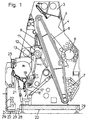
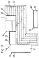
- the distributor 1 shown in FIG. 1 is an aggregate of the cigarette rod making machine 2 according to FIG. 3 with a high throughput of flowing process air for the purpose of supplying and classifying tobacco and building up a tobacco rod from a tobacco stream.
- the tobacco is dispensed in portions into a storage container 4 of the distributor 1 via a pneumatic lock system 3, transferred to a buffer store 7 via a rake roller 6, transported upwards by a removal conveyor 8 loaded with drivers and discharged into a storage chute 9, the filling level of which is kept essentially constant .
- a removal roller 11 continuously takes tobacco from the storage shaft 9 and, in cooperation with a beater roller 12, delivers it to a chute 13.
- the tobacco is separated into heavier and lighter tobacco fibers by a transverse air flow generated by blowing air nozzles 14, the latter of which reach a concave curved guide surface 16 and the former downwards via a cellular wheel lock 17 into a viewing shaft 18, from which through repeated sighting heavy ribs discharged downwards and lighter tobacco fibers as a result of the injector effect of a blast air jet generated by a further nozzle arrangement 19 transported upwards and combined with the other tobacco fibers on the guide surface 16 and extending to the width of the distributor 1 (perpendicular to the plane of the drawing) Tobacco stream are built up, which is supported and accelerated by additional blown air from a further nozzle arrangement 21 emerging at the guide surface 16.
- the tobacco flow is directed upwards to one perpendicular to the plane of the drawing transferred suction train conveyor 25, on which using flowing suction air a tobacco rod is built up, which in the further course of Cigarette rod machine 2 is wrapped and processed into single cigarettes.
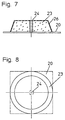
- the outer machine walls, flaps, doors, hoods or trolleys facing the operating room or the floor area and acting as reflective surfaces are largely provided with sound-absorbing material in the form of damping mats 22, which in the area of the outer machine walls as shape-neutral, 7, for example, are designed as frustoconical damping elements 23, which are connected by a central screw connection 24 in an easily replaceable manner to the differently dimensioned cladding sheets of the machine.
- the damping elements 23 facing the operating space with their sound-absorbing structure are covered on all absorption surfaces according to FIG. 7 with sieve-like cladding panels 26 which are perforated in a sieve-like manner.
- damping mats 22 on the machine floor are designed such that they limit a sufficiently large air inlet opening 27 and act as a silencer 28 on the inflowing air 29. In this way, the process air is largely supplied via the machine floor instead of through gaps in the front or rear machine cladding.
- damping mats 22 are designed in the same way on the front and rear machine cladding and attached to the machine floor in the form of a muffler 28 for a central air inlet opening 27.
- the floor is covered with a damping mat 22.
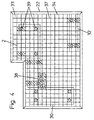
- the damping mat 22 is designed according to FIG. 4 and covers the entire footprint of the production line 35.
- the damping mat 22 consists of individual damping tiles 33, which according to FIG. 5 are designed as tile boxes 34, which have grid-like support supports 36 and are equipped with damping material in the form of precisely fitted damping mats 22.
- the tile boxes 34 are provided with a grating support 37 screwed to the support supports 36. According to the layout of the production line 31, load-specific supports are inserted into the grating supports 37 according to FIG.
- the remaining gaps 41 on the machines 2 and 30 are designed to be largely sound-absorbing, as shown in FIG.
- the air sucked in by a blower 42 is conducted inside the machines through sound-damped flow channels 43, 44, 46 and discharged via an air outlet 47 on the top, which additionally supports sound damping.
- parts which correspond to those of the arrangements described above are provided with reference numbers increased by a hundred.
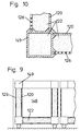
- inner and outer sound-permeable cladding panels 126 with a reflecting surface 120 arranged in between are inserted into receiving grooves of four profiled strips 154 assembled by means of corner connectors 152 to form a profiled frame 153.
- the cavities formed are filled with damping mats 122.
- Sealing elements 157 are inserted into the profile frame 153, which can be pivoted about an axis 156.
- the cladding plates 126 and the reflection surface 120 are stabilized against warping by means of spacer sleeves 158 which are screwed together.
- a profile strip 161 has one Window frames as double glazing two viewing windows 162 and 163 as well a cladding sheet 126 is used, which delimits a cavity which with Damping mats 122 is filled.
- the last exemplary embodiment is a grating support for a floor damping tile 233 237 with rounded edges 267 and one between one on the Damping mat 222 overlying close-meshed sieve and the grid support 237 inserted sound-permeable film 269 provided that the passage of Prevents fine particles in the damping material.
Landscapes
- Manufacturing Of Cigar And Cigarette Tobacco (AREA)
- Building Environments (AREA)
- Soundproofing, Sound Blocking, And Sound Damping (AREA)
- Duct Arrangements (AREA)
- Exhaust Silencers (AREA)
Abstract
Description
Derartige schalldämpfende Leitungsabschnitte sind gemäß einer bevorzugten Weiterbildung auf den Bodenbereich der Produktionsmaschinen konzentriert.
Gemäß einer vorteilhaften Weiterbildung lassen sich die Dämpfungsmaßnahmen im Bodenbereich besonders effektiv dadurch unterstützen, dass in die schalldämpfenden Leitungsabschnitte eine schallabsorbierende Bodenbedeckung unter den Produktionsmaschinen einbezogen ist.
Um die Schallschutzmaßnahmen zu optimieren, wird weiterhin vorgeschlagen, dass nachrangige Luftströmungsspalte zwischen beweglichen oder starren Maschinen-bzw. Wandungssektionen als Schalldämpfer ausgebildet sind.
Gemäß vorteilhaften Weiterbildungen werden die Strömungsgeräusche zusätzlich dadurch unterdrückt, dass zur Schalldämpfung der Luftströmungsspalte eine Außenverkleidung der Produktionsmaschinen bildende Dämpfungsmatten einbezogen sind.
Als zusätzlich lärmmindernde Maßnahmen wird weiterhin vorgeschlagen, dass schallgedämpfte Luftaustrittsöffnungen an der Oberseite der Produktionsmaschinen vorgesehen sind, so dass die Lärmabstrahlung dem unmittelbaren Bedienungsbereich abgewandt ist.
- Figur 1
- eine Schnittdarstellung durch den Verteiler einer Zigarettenstrangmaschine,
- Figur 2
- eine Schnittdarstellung durch eine Filteransetzmaschine,
- Figur 3
- eine Draufsicht auf eine aus einer Zigarettenmaschine und einer Filteransetzmaschine gebildete winkelförmige Produktionslinie,
- Figur 4
- ein Bodenplan für Schalldämpfungsmaterial zur Aufstellung der Produktionslinie gemäß Figur 3,
- Figur 5
- einen Querschnitt durch ein Fliesenelement des Schalldämpfungsmaterials gemäß Figur 4,
- Figur 6
- eine Draufsicht auf das Fliesenelement gemäß Figur 5,
- Figur 7
- einen Querschnitt durch ein Schalldämpfungselement der Maschinenverkleidung,
- Figur 8
- eine Draufsicht auf das Schalldämpfungselement gemäß Figur 7,
- Figur 9
- eine alternative Dämpfungs-Verkleidung an einer als herausziehbarer Wagen gemäß den Figuren 1, 2 ausgebildeten Maschinenwand,
- Figur 10
- einen Querschnitt durch eine Eckprofilleiste des Wagens gemäß Figur 9,
- Figur 11
- einen Querschnitt durch ein alternatives Dämpfungsprofil an einer als Tür ausgebildeten Maschinenverkleidung,
- Figur 12
- eine Vorderansicht der Tür gemäß Figur 11,
- Figur 13
- einen Querschnitt durch eine Einzelheit des Tür-Dämpfungsprofils,
- Figur 14
- einen Querschnitt durch ein Dämpfungsprofil einer als durchsichtige Klappe ausgebildeten Maschinenverkleidung,
- Figur 15
- einen Querschnitt durch eine alternative Dämpfungsfliese zur Bodenbedeckung,
- Figur 16
- eine Draufsicht auf die Dämpfungsfliese gemäß Figur 15 und
- Figur 17
- einen Teilquerschnitt durch eine weitere Ausführungsform der Dämpfungsfliese.
Eine Entnahmewalze 11 entnimmt kontinuierlich Tabak aus dem Stauschacht 9 und gibt ihn in Zusammenwirkung mit einer Schlägerwalze 12 in einen Fallschacht 13 ab.
Am unteren Austritt des Fallschachtes 13 wird der Tabak durch einen mittels Blasluftdüsen 14 erzeugten quergerichteten Sichtluftstrom in schwerere und leichtere Tabakfasern getrennt, von denen letztere auf eine konkav gekrümmte Leitfläche 16 und erstere abwärts über eine Zellenradschleuse 17 in einen Sichtschacht 18 gelangen, von dem aus durch nochmalige Sichtung schwere Rippen nach unten ausgetragen und leichtere Tabakfasern infolge der Injektorwirkung eines durch eine weitere Düsenanordnung 19 erzeugten Blasluftstrahls nach oben transportiert und mit den übrigen Tabakfasern auf der Leitfläche 16 vereinigt und zu einem sich über die Breite des Verteilers 1 (senkrecht zur Zeichenebene) erstreckenden Tabakstrom aufgebaut werden, was durch zusätzliche Blasluft aus einer weiteren an der Leitfläche 16 austretenden Düsenanordnung 21 unterstützt und beschleunigt wird.
Auf erfindungsgemäße Weise sind die äußeren dem Bedienungsraum bzw. dem Bodenbereich zugewandten, als Reflexionsflächen wirkenden Maschinenwände-, Klappen-, Türen-, Hauben- oder Wagen weitestgehend mit schalldämpfendem Material in Form von Dämpfungsmatten 22 versehen, welche im Bereich der äußeren Maschinenwände als formneutrale, beispielsweise gemäß Figur 7 als kegelstumpfförmige Dämpfungselemente 23 ausgebildet sind, die durch eine zentrale Verschraubung 24 in leicht auswechselbarer Weise mit den unterschiedlich bemessenen Verkleidungsblechen der Maschine verbunden sind.
Die mit ihrer schalldämpfenden Struktur dem Bedienungsraum zugewandten Dämpfungselemente 23 sind an allen Absorptionsflächen gemäß Figur 7 mit siebartig durchbrochenen, schalldurchlässigen Verkleidungsblechen 26 bedeckt.
Bei der in Figur 2 dargestellten Filteransetzmaschine 29, die ebenfalls mit einem hohen Luftdurchsatz zum Halten von stabförmigen Tabakartikeln in den Mulden von Fördertrommeln 31 sowie zum Prüfen und Aussondern von Artikeln betrieben wird, sind in gleicher Weise ausgebildet Dämpfungsmatten 22 an der vorderen und hinteren Maschinenverkleidung sowie am Maschinenboden in Form eines Schalldämpfers 28 für eine zentrale Lufteintrittsöffnung 27 angebracht.
Zusätzlich ist der Fußboden zumindest im Bereich des Standstreifens vor der Maschine bis unter den Maschinenboden mit einer Dämpfungsmatte 22 belegt.
Entsprechend dem Aufstellungsplan der Produktionslinie 31 sind in die Gitterrostauflagen 37 gemäß Figur 4 belastungsspezifische Auflagen eingefügt, beispielsweise an Stellen mit stärkeren Partikelansammlungen in Form von leicht zu reinigenden geschlossenen Platten 38 oder unter den Maschinenständern in Form verstärkter Stützplatten 39.
Als weitere Lärmschutzmaßnahme sind gemäß Figur 2 die verbleibenden Spalte 41 an den Maschinen 2 und 30 weitestgehend schalldämpfend gestaltet.
Die durch ein Gebläse 42 angesaugte Luft wird innerhalb der Maschinen durch schallgedämpfte Strömungskanäle 43, 44, 46 geleitet und über einen oberseitigen Luftaustritt 47 abgeführt, was zusätzlich die Schalldämpfung unterstützt.
Bei den in den Figuren 9 bis 16 dargestellten alternativen Ausgestaltungen der Dämpfungselemente sind Teile, die denen der zuvor beschriebenen Anordnungen entsprechen mit um hundert erhöhten Bezugszahlen versehen.
In den um eine Achse 156 schwenkbaren Profilrahmen 153 sind Dichtungselemente 157 eingesetzt. Die Verkleidungsbleche 126 und die Reflexionsfläche 120 sind mittels miteinander verschraubter Distanzhülsen 158 gegen Verwerfungen stabilisiert.
Darüber hinaus sind die Dämpfungsfliesen 133 seitlich und bodenseitig mit eingesetzten Körperschallübertragung zwischen den Dämpfungsfliesen sowie zum Boden hin verhindernden Puffern 166 versehen.
Claims (6)
- Anordnung zur Absenkung des Lärmpegels an durch strömende Prozessluft beaufschlagten Produktionsmaschinen der tabakverarbeitenden Industrie, insbesondere im Bedienungsbereich einer durch wenigstens zwei in einem Winkel zueinander angeordneten Produktionsmaschinen gebildeten Produktionslinie, dadurch gekennzeichnet, dass den Produktionsmaschinen (1, 30) zugeführte Prozessluft zum überwiegenden Teil über schalldämpfende Leitungsabschnitte (27) geleitet wird.
- Anordnung nach Anspruch 1, dadurch gekennzeichnet, dass die schalldämpfenden Leitungsabschnitte (27) auf den Bodenbereich der Produktionsmaschinen (1, 30) konzentriert sind.
- Anordnung nach Anspruch 1 oder 2, dadurch gekennzeichnet, dass in die schalldämpfenden Leitungsabschnitte (27) eine schallabsorbierende Bodenbedeckung (22) unter den Produktionsmaschinen (1, 30) einbezogen ist.
- Anordnung nach einem der Ansprüche 1 bis 3, dadurch gekennzeichnet, dass nachrangige Luftströmungsspalte (41) zwischen beweglichen oder starren Maschinen- bzw. Wandungssektionen als Schalldämpfer (28) ausgebildet sind.
- Anordnung nach Anspruch 4, dadurch gekennzeichnet, dass zur Schalldämpfung der Luftströmungsspalte eine Außenverkleidung der Produktionsmaschinen (1, 30) bildende Dämpfungsmatten (22) einbezogen sind.
- Anordnung nach einem der Ansprüche 1 bis 5, dadurch gekennzeichnet, dass schalldämpfende Luftaustrittsöffnungen (47) an der Oberseite der Produktionsmaschinen (30) vorgesehen sind.
Applications Claiming Priority (2)
| Application Number | Priority Date | Filing Date | Title |
|---|---|---|---|
| DE19943319A DE19943319A1 (de) | 1999-09-10 | 1999-09-10 | Anordnung zur Absenkung des Lärmpegels an durch strömende Prozeßluft beaufschlagten Produktionsmaschinen der tabakverarbeitenden Industrie |
| DE19943319 | 1999-09-10 |
Publications (3)
| Publication Number | Publication Date |
|---|---|
| EP1082914A2 true EP1082914A2 (de) | 2001-03-14 |
| EP1082914A3 EP1082914A3 (de) | 2003-08-13 |
| EP1082914B1 EP1082914B1 (de) | 2005-06-22 |
Family
ID=7921499
Family Applications (1)
| Application Number | Title | Priority Date | Filing Date |
|---|---|---|---|
| EP00118578A Expired - Lifetime EP1082914B1 (de) | 1999-09-10 | 2000-08-26 | Anordnung zur Absenkung des Lärmpegels an durch strömende Prozessluft beaufschlagten Produktionsmaschinen der tabakverarbeitenden Industrie |
Country Status (8)
| Country | Link |
|---|---|
| US (1) | US6431310B1 (de) |
| EP (1) | EP1082914B1 (de) |
| JP (1) | JP2001154677A (de) |
| CN (1) | CN1179672C (de) |
| AT (1) | ATE298207T1 (de) |
| DE (2) | DE19943319A1 (de) |
| ES (1) | ES2242566T3 (de) |
| PL (1) | PL198888B1 (de) |
Families Citing this family (7)
| Publication number | Priority date | Publication date | Assignee | Title |
|---|---|---|---|---|
| US6564900B1 (en) * | 2000-11-22 | 2003-05-20 | Ge Medical Systems Global Technology Company, Llc | Method and apparatus for reducing acoustic noise in MRI scanners |
| ITBO20030704A1 (it) * | 2003-11-21 | 2005-05-22 | Gd Spa | Macchina automatica per la lavorazione di articoli da fumo. |
| JP4389768B2 (ja) * | 2004-11-25 | 2009-12-24 | 株式会社デンソー | 車載装置 |
| JPWO2013105635A1 (ja) * | 2012-01-13 | 2015-05-11 | 株式会社ニコン | チャンバー装置 |
| US9253556B1 (en) * | 2013-08-29 | 2016-02-02 | ConcealFab Corporation | Dissipative system for increasing audio entropy thereby diminishing auditory perception |
| CN104621711B (zh) * | 2015-01-25 | 2016-06-29 | 常德烟草机械有限责任公司 | 一种卷接机组的降噪方法及其装置 |
| EP3786943A4 (de) * | 2018-04-25 | 2021-04-21 | Mitsubishi Electric Corporation | Gehäuse für eine elektrische vorrichtung, kältekreislaufvorrichtung und elektrische vorrichtung |
Family Cites Families (11)
| Publication number | Priority date | Publication date | Assignee | Title |
|---|---|---|---|---|
| GB1442751A (en) * | 1972-05-05 | 1976-07-14 | Molins Ltd | Cigarette making machines |
| DE7404292U (de) * | 1973-04-18 | 1978-03-30 | Hauni-Werke Koerber & Co Kg, 2050 Hamburg | Maschine zum herstellen von produkten der tabakverarbeitenden industrie |
| JPS6219420Y2 (de) * | 1978-09-07 | 1987-05-18 | ||
| DE2910371A1 (de) * | 1979-03-16 | 1980-10-02 | Eberspaecher J | Belueftungsvorrichtung fuer abgedichtete raeume |
| JPS58152699U (ja) * | 1982-04-06 | 1983-10-13 | 小型ガス冷房技術研究組合 | 防音箱 |
| JPH0516639Y2 (de) * | 1988-07-21 | 1993-04-30 | ||
| DE3931228A1 (de) * | 1988-09-16 | 1990-03-22 | Hansa Ventilatoren Masch | Schalldaempfer |
| JPH02114993U (de) * | 1989-02-28 | 1990-09-14 | ||
| JPH059797U (ja) * | 1991-07-25 | 1993-02-09 | 株式会社アマダ | 振動性構造体の防音装置 |
| JPH0635479A (ja) * | 1992-07-15 | 1994-02-10 | Amada Co Ltd | 防音ボックス |
| JP3085430B2 (ja) * | 1993-02-10 | 2000-09-11 | 東京瓦斯株式会社 | 防振、防音装置用支持機構 |
-
1999
- 1999-09-10 DE DE19943319A patent/DE19943319A1/de not_active Ceased
-
2000
- 2000-08-26 AT AT00118578T patent/ATE298207T1/de not_active IP Right Cessation
- 2000-08-26 EP EP00118578A patent/EP1082914B1/de not_active Expired - Lifetime
- 2000-08-26 DE DE50010595T patent/DE50010595D1/de not_active Expired - Lifetime
- 2000-08-26 ES ES00118578T patent/ES2242566T3/es not_active Expired - Lifetime
- 2000-08-30 US US09/650,741 patent/US6431310B1/en not_active Expired - Fee Related
- 2000-09-06 JP JP2000269732A patent/JP2001154677A/ja active Pending
- 2000-09-07 PL PL342421A patent/PL198888B1/pl unknown
- 2000-09-08 CN CNB00126348XA patent/CN1179672C/zh not_active Expired - Fee Related
Non-Patent Citations (1)
| Title |
|---|
| None |
Also Published As
| Publication number | Publication date |
|---|---|
| ATE298207T1 (de) | 2005-07-15 |
| EP1082914A3 (de) | 2003-08-13 |
| PL198888B1 (pl) | 2008-07-31 |
| DE19943319A1 (de) | 2001-03-15 |
| EP1082914B1 (de) | 2005-06-22 |
| US6431310B1 (en) | 2002-08-13 |
| JP2001154677A (ja) | 2001-06-08 |
| DE50010595D1 (de) | 2005-07-28 |
| CN1287813A (zh) | 2001-03-21 |
| ES2242566T3 (es) | 2005-11-16 |
| CN1179672C (zh) | 2004-12-15 |
| PL342421A1 (en) | 2001-03-12 |
Similar Documents
| Publication | Publication Date | Title |
|---|---|---|
| EP1931480B2 (de) | Vorrichtung und verfahren zum abtrennen von nasslack-overspray | |
| EP2080971A2 (de) | Vorrichtung und Verfahren zur Trocknung von Gegenständen, insbesondere von Flüssigkeitsbehältern | |
| EP1486642A2 (de) | Entstauber mit Mehrstrahldüsen | |
| DE8707059U1 (de) | Sandstrahlkabine | |
| AT391015B (de) | Einrichtung zur schallgedaempften belueftung von raeumen | |
| EP1082914B1 (de) | Anordnung zur Absenkung des Lärmpegels an durch strömende Prozessluft beaufschlagten Produktionsmaschinen der tabakverarbeitenden Industrie | |
| WO1982003114A1 (en) | Air conditionned room and method for using same | |
| EP1082915B1 (de) | Anordnung zur Absenkung des Lärmpegels an Produktionsmaschinen der tabakverarbeitenden Industrie | |
| CH674994A5 (de) | ||
| DE102016117384A1 (de) | Sichter | |
| AT519034B1 (de) | Sichter | |
| DE4439856A1 (de) | Vorrichtung zum Binden von Staub in Wasser | |
| DE4443231A1 (de) | Aufbereitungsvorrichtung für Gestein und/oder Recyclingmaterial, insbesondere Brecher | |
| EP0958977A2 (de) | Reinigungsvorrichtung für Karosserien von Fahrzeugen | |
| DE19600040A1 (de) | Schalldämpferelement, insbesondere für einen Kulissenschalldämfper | |
| DE19959821B4 (de) | Auffangbehälter an tabakverarbeitenden Maschinen | |
| DE29515615U1 (de) | Arbeitskabinensystem zur Reinigung und Oberflächenbehandlung von Gegenständen | |
| DE19940286C2 (de) | Instrumententafel für ein Kraftfahrzeug | |
| DE19922115B4 (de) | Sauganlage für eine Kreuzspulen herstellende Textilmaschine | |
| DE8632260U1 (de) | Personen-Abreinigungsstation zum Aufstellen in Arbeitsbereichen | |
| DE2534370B2 (de) | Schalldaempfender kanal fuer die foerderung von stueckigem gut | |
| DE9100929U1 (de) | Vorrichtung zum Aufsaugen von Gegenständen | |
| DE2819657A1 (de) | Schalldaemmeinrichtung und verfahren zu deren herstellung | |
| DE29506475U1 (de) | Bearbeitungsmaschine | |
| DE1931346A1 (de) | Schalldaemmendes Fenster mit schallgedaempften Lueftungsschleusen |
Legal Events
| Date | Code | Title | Description |
|---|---|---|---|
| PUAI | Public reference made under article 153(3) epc to a published international application that has entered the european phase |
Free format text: ORIGINAL CODE: 0009012 |
|
| AK | Designated contracting states |
Kind code of ref document: A2 Designated state(s): AT BE CH CY DE DK ES FI FR GB GR IE IT LI LU MC NL PT SE |
|
| AX | Request for extension of the european patent |
Free format text: AL;LT;LV;MK;RO;SI |
|
| PUAL | Search report despatched |
Free format text: ORIGINAL CODE: 0009013 |
|
| AK | Designated contracting states |
Designated state(s): AT BE CH CY DE DK ES FI FR GB GR IE IT LI LU MC NL PT SE |
|
| AX | Request for extension of the european patent |
Extension state: AL LT LV MK RO SI |
|
| 17P | Request for examination filed |
Effective date: 20040114 |
|
| AKX | Designation fees paid |
Designated state(s): AT BE CH CY DE DK ES FI FR GB GR IE IT LI LU MC NL PT SE |
|
| 17Q | First examination report despatched |
Effective date: 20040811 |
|
| GRAP | Despatch of communication of intention to grant a patent |
Free format text: ORIGINAL CODE: EPIDOSNIGR1 |
|
| GRAS | Grant fee paid |
Free format text: ORIGINAL CODE: EPIDOSNIGR3 |
|
| GRAA | (expected) grant |
Free format text: ORIGINAL CODE: 0009210 |
|
| AK | Designated contracting states |
Kind code of ref document: B1 Designated state(s): AT BE CH CY DE DK ES FI FR GB GR IE IT LI LU MC NL PT SE |
|
| PG25 | Lapsed in a contracting state [announced via postgrant information from national office to epo] |
Ref country code: IE Free format text: LAPSE BECAUSE OF FAILURE TO SUBMIT A TRANSLATION OF THE DESCRIPTION OR TO PAY THE FEE WITHIN THE PRESCRIBED TIME-LIMIT Effective date: 20050622 Ref country code: FI Free format text: LAPSE BECAUSE OF FAILURE TO SUBMIT A TRANSLATION OF THE DESCRIPTION OR TO PAY THE FEE WITHIN THE PRESCRIBED TIME-LIMIT Effective date: 20050622 |
|
| REG | Reference to a national code |
Ref country code: GB Ref legal event code: FG4D Free format text: NOT ENGLISH |
|
| REG | Reference to a national code |
Ref country code: CH Ref legal event code: EP |
|
| GBT | Gb: translation of ep patent filed (gb section 77(6)(a)/1977) |
Effective date: 20050622 |
|
| REG | Reference to a national code |
Ref country code: IE Ref legal event code: FG4D Free format text: LANGUAGE OF EP DOCUMENT: GERMAN |
|
| REF | Corresponds to: |
Ref document number: 50010595 Country of ref document: DE Date of ref document: 20050728 Kind code of ref document: P |
|
| PG25 | Lapsed in a contracting state [announced via postgrant information from national office to epo] |
Ref country code: LU Free format text: LAPSE BECAUSE OF NON-PAYMENT OF DUE FEES Effective date: 20050826 Ref country code: CY Free format text: LAPSE BECAUSE OF FAILURE TO SUBMIT A TRANSLATION OF THE DESCRIPTION OR TO PAY THE FEE WITHIN THE PRESCRIBED TIME-LIMIT Effective date: 20050826 Ref country code: AT Free format text: LAPSE BECAUSE OF NON-PAYMENT OF DUE FEES Effective date: 20050826 |
|
| PG25 | Lapsed in a contracting state [announced via postgrant information from national office to epo] |
Ref country code: MC Free format text: LAPSE BECAUSE OF NON-PAYMENT OF DUE FEES Effective date: 20050831 Ref country code: BE Free format text: LAPSE BECAUSE OF NON-PAYMENT OF DUE FEES Effective date: 20050831 |
|
| PG25 | Lapsed in a contracting state [announced via postgrant information from national office to epo] |
Ref country code: DK Free format text: LAPSE BECAUSE OF FAILURE TO SUBMIT A TRANSLATION OF THE DESCRIPTION OR TO PAY THE FEE WITHIN THE PRESCRIBED TIME-LIMIT Effective date: 20050922 Ref country code: SE Free format text: LAPSE BECAUSE OF FAILURE TO SUBMIT A TRANSLATION OF THE DESCRIPTION OR TO PAY THE FEE WITHIN THE PRESCRIBED TIME-LIMIT Effective date: 20050922 Ref country code: GR Free format text: LAPSE BECAUSE OF FAILURE TO SUBMIT A TRANSLATION OF THE DESCRIPTION OR TO PAY THE FEE WITHIN THE PRESCRIBED TIME-LIMIT Effective date: 20050922 |
|
| REG | Reference to a national code |
Ref country code: ES Ref legal event code: FG2A Ref document number: 2242566 Country of ref document: ES Kind code of ref document: T3 |
|
| PG25 | Lapsed in a contracting state [announced via postgrant information from national office to epo] |
Ref country code: PT Free format text: LAPSE BECAUSE OF FAILURE TO SUBMIT A TRANSLATION OF THE DESCRIPTION OR TO PAY THE FEE WITHIN THE PRESCRIBED TIME-LIMIT Effective date: 20051129 |
|
| REG | Reference to a national code |
Ref country code: IE Ref legal event code: FD4D |
|
| PLBE | No opposition filed within time limit |
Free format text: ORIGINAL CODE: 0009261 |
|
| STAA | Information on the status of an ep patent application or granted ep patent |
Free format text: STATUS: NO OPPOSITION FILED WITHIN TIME LIMIT |
|
| 26N | No opposition filed |
Effective date: 20060323 |
|
| EN | Fr: translation not filed | ||
| PG25 | Lapsed in a contracting state [announced via postgrant information from national office to epo] |
Ref country code: FR Free format text: LAPSE BECAUSE OF FAILURE TO SUBMIT A TRANSLATION OF THE DESCRIPTION OR TO PAY THE FEE WITHIN THE PRESCRIBED TIME-LIMIT Effective date: 20060818 |
|
| PGFP | Annual fee paid to national office [announced via postgrant information from national office to epo] |
Ref country code: ES Payment date: 20070813 Year of fee payment: 8 |
|
| PGFP | Annual fee paid to national office [announced via postgrant information from national office to epo] |
Ref country code: CH Payment date: 20070827 Year of fee payment: 8 |
|
| BERE | Be: lapsed |
Owner name: HAUNI MASCHINENBAU A.G. Effective date: 20050831 |
|
| PG25 | Lapsed in a contracting state [announced via postgrant information from national office to epo] |
Ref country code: FR Free format text: LAPSE BECAUSE OF FAILURE TO SUBMIT A TRANSLATION OF THE DESCRIPTION OR TO PAY THE FEE WITHIN THE PRESCRIBED TIME-LIMIT Effective date: 20050831 |
|
| PG25 | Lapsed in a contracting state [announced via postgrant information from national office to epo] |
Ref country code: FR Free format text: LAPSE BECAUSE OF FAILURE TO SUBMIT A TRANSLATION OF THE DESCRIPTION OR TO PAY THE FEE WITHIN THE PRESCRIBED TIME-LIMIT Effective date: 20050622 |
|
| REG | Reference to a national code |
Ref country code: CH Ref legal event code: PL |
|
| PG25 | Lapsed in a contracting state [announced via postgrant information from national office to epo] |
Ref country code: LI Free format text: LAPSE BECAUSE OF NON-PAYMENT OF DUE FEES Effective date: 20080831 Ref country code: CH Free format text: LAPSE BECAUSE OF NON-PAYMENT OF DUE FEES Effective date: 20080831 |
|
| REG | Reference to a national code |
Ref country code: ES Ref legal event code: FD2A Effective date: 20080827 |
|
| PG25 | Lapsed in a contracting state [announced via postgrant information from national office to epo] |
Ref country code: ES Free format text: LAPSE BECAUSE OF NON-PAYMENT OF DUE FEES Effective date: 20080827 |
|
| PGFP | Annual fee paid to national office [announced via postgrant information from national office to epo] |
Ref country code: NL Payment date: 20140821 Year of fee payment: 15 Ref country code: DE Payment date: 20140902 Year of fee payment: 15 |
|
| PGFP | Annual fee paid to national office [announced via postgrant information from national office to epo] |
Ref country code: GB Payment date: 20140826 Year of fee payment: 15 |
|
| PGFP | Annual fee paid to national office [announced via postgrant information from national office to epo] |
Ref country code: IT Payment date: 20140806 Year of fee payment: 15 |
|
| REG | Reference to a national code |
Ref country code: DE Ref legal event code: R119 Ref document number: 50010595 Country of ref document: DE |
|
| GBPC | Gb: european patent ceased through non-payment of renewal fee |
Effective date: 20150826 |
|
| PG25 | Lapsed in a contracting state [announced via postgrant information from national office to epo] |
Ref country code: IT Free format text: LAPSE BECAUSE OF NON-PAYMENT OF DUE FEES Effective date: 20150826 |
|
| REG | Reference to a national code |
Ref country code: NL Ref legal event code: MM Effective date: 20150901 |
|
| PG25 | Lapsed in a contracting state [announced via postgrant information from national office to epo] |
Ref country code: NL Free format text: LAPSE BECAUSE OF NON-PAYMENT OF DUE FEES Effective date: 20150901 |
|
| PG25 | Lapsed in a contracting state [announced via postgrant information from national office to epo] |
Ref country code: DE Free format text: LAPSE BECAUSE OF NON-PAYMENT OF DUE FEES Effective date: 20160301 Ref country code: GB Free format text: LAPSE BECAUSE OF NON-PAYMENT OF DUE FEES Effective date: 20150826 |