EP1081429A2 - Fahrzeugscheinwerfer mit einer darin eingesetzten Baueinheit - Google Patents
Fahrzeugscheinwerfer mit einer darin eingesetzten Baueinheit Download PDFInfo
- Publication number
- EP1081429A2 EP1081429A2 EP00118810A EP00118810A EP1081429A2 EP 1081429 A2 EP1081429 A2 EP 1081429A2 EP 00118810 A EP00118810 A EP 00118810A EP 00118810 A EP00118810 A EP 00118810A EP 1081429 A2 EP1081429 A2 EP 1081429A2
- Authority
- EP
- European Patent Office
- Prior art keywords
- reflector
- cover plate
- holding frame
- vehicle headlight
- housing
- Prior art date
- Legal status (The legal status is an assumption and is not a legal conclusion. Google has not performed a legal analysis and makes no representation as to the accuracy of the status listed.)
- Granted
Links
- 230000003287 optical effect Effects 0.000 title claims 2
- 239000000853 adhesive Substances 0.000 claims abstract description 18
- 230000001070 adhesive effect Effects 0.000 claims abstract description 18
- 238000009423 ventilation Methods 0.000 claims description 4
- XLYOFNOQVPJJNP-UHFFFAOYSA-N water Substances O XLYOFNOQVPJJNP-UHFFFAOYSA-N 0.000 claims description 3
- 230000015572 biosynthetic process Effects 0.000 description 1
- 239000002131 composite material Substances 0.000 description 1
- 230000000149 penetrating effect Effects 0.000 description 1
- 238000009417 prefabrication Methods 0.000 description 1
- 210000001364 upper extremity Anatomy 0.000 description 1
Images


Classifications
-
- F—MECHANICAL ENGINEERING; LIGHTING; HEATING; WEAPONS; BLASTING
- F21—LIGHTING
- F21S—NON-PORTABLE LIGHTING DEVICES; SYSTEMS THEREOF; VEHICLE LIGHTING DEVICES SPECIALLY ADAPTED FOR VEHICLE EXTERIORS
- F21S45/00—Arrangements within vehicle lighting devices specially adapted for vehicle exteriors, for purposes other than emission or distribution of light
- F21S45/30—Ventilation or drainage of lighting devices
- F21S45/33—Ventilation or drainage of lighting devices specially adapted for headlamps
-
- F—MECHANICAL ENGINEERING; LIGHTING; HEATING; WEAPONS; BLASTING
- F21—LIGHTING
- F21S—NON-PORTABLE LIGHTING DEVICES; SYSTEMS THEREOF; VEHICLE LIGHTING DEVICES SPECIALLY ADAPTED FOR VEHICLE EXTERIORS
- F21S41/00—Illuminating devices specially adapted for vehicle exteriors, e.g. headlamps
- F21S41/20—Illuminating devices specially adapted for vehicle exteriors, e.g. headlamps characterised by refractors, transparent cover plates, light guides or filters
- F21S41/29—Attachment thereof
Definitions
- the invention relates to a vehicle headlight the specified in the preamble of claim 1 Art.
- Such a vehicle headlight is from the patent DE 197 28 446 C1 known. Although with this headlight also the reflector, the cover plate and the holding frame firmly glued to each other, the adhesive bed is located between the inside of the wreath the cover plate and the outside of the reflector wall, and it dips the holding frame with a hook web that goes over the rim of the cover plate engages in the adhesive bed. Both with regard to the prefabrication of the entire structural unit as well as the profile design of the holding frame known arrangement impractical.
- the invention is therefore based on the object To create vehicle headlights of the generic type, in which the attachment of the adhesive bed is made easier can be without a complicated design the holding frame is required.
- This task is the generic type in a vehicle headlight kind by the characteristic features of the Claim 1 solved.
- the filling space for the Adhesive bed that is from the outside of the reflector wall Face of the ring on the cover plate and the inside the holding frame is limited, a circumferential, in gives essentially the same wide gap everywhere, from the the adhesive bed can be inserted from the opening side can, which immediately the reflector, the cover plate and firmly connects the holding frame with each other without Add-on parts are subsequently inserted into the adhesive bed have to.
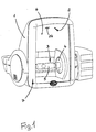
- FIG. 1 shows a housing 1 of the Headlight, in which a reflector 2 as part of a unit used therein is included.
- a gas discharge lamp 3 is used, of which the burner 5 and part of the lamp base 4 is shown.
- the reflector 2 At the The opening side is the reflector 2 by means of a cover plate 6 tightly closed with the reflector 2 and a holding frame 7, which is the connection to the opening edge of the housing 1 produces.
- the type of connection between the reflector 2, the cover plate 6 and the holding frame 7 goes out in detail Figures 2 and 3 emerge.
- the holding frame 7 acts it is an angle profile, which has a front Leg 8 of the width direction or height direction of the Headlamp is arranged, and one in the depth direction of the headlight arranged second leg 9.
- the cover 6 has a circumferential rear, to Housing 1 facing collar 10, on the outside 11th on the one hand and on the front 20 of the cover plate 6 on the other the holding frame 7 nestles.
- the reflector 2 On the inside the ring 10 of the cover plate 6 is the reflector 2 with its wall 14, which to the edge 13 on the Opening side of the reflector 2 extends.
- the outside 15 of the reflector wall 14 and the inside 17 of the Legs 9 of the holding frame 7 are towards the housing 1 out over the end face 16 of the ring 10 of the cover plate 6 extended.
- This filling space 18 and accordingly the adhesive bed 19 are all around the reflector edge 13 arranged around so that all around the opening side of the reflector 2 around a firm, waterproof composite with the cover plate 6 and the holding frame 7.
- the opening side of the filling space 18, that of the end face 16 of the ring 10 on the cover plate 6 is opposite, forms a circumferential gap over which the adhesive bed 19 can be easily introduced.
- Fig. 4 illustrates that in the installed position of the filling space 18 for the adhesive bed 19 inside the housing 1 in one Intermediate chamber 21 opens out at the lowest point of the Housing 1 has a water drain opening 23.
- a vent 24 is provided in the reflector, the inside of the reflector 2 with the intermediate chamber 21 connects.
- the ventilation opening 24 on the reflector 2 Up in the area of the intermediate chamber 21 the ventilation opening 24 on the reflector 2 by means of a Covered 25. Penetrating into the intermediate chamber 21 So water can neither past the adhesive bed 19 nor via the ventilation opening 24 to the inside of the reflector 2 arrive.
- the Ventilation opening 24 heated, dry air from the reflector interior into the intermediate chamber 21, which is in an antechamber below the hood 25 holds. When switching off the headlight turns from this antechamber below the scraper 25 the dry air back into the interior of the reflector sucked in. This creates the formation of moisture deposits prevented within the reflector interior.
Landscapes
- Engineering & Computer Science (AREA)
- General Engineering & Computer Science (AREA)
- Non-Portable Lighting Devices Or Systems Thereof (AREA)
- Lighting Device Outwards From Vehicle And Optical Signal (AREA)
- Securing Globes, Refractors, Reflectors Or The Like (AREA)
Abstract
Description
- Fig. 1
- eine perspektivische Vorderansicht eines Fahrzeugscheinwerfers,
- Fig. 2
- einen Teilschnitt durch die in den Fahrzeugscheinwerfer eingesetzte Baueinheit im Verbindungsbereich des Reflektors der Abdeckscheibe und des Halterahmens,
- Fig. 3
- einen der Fig. 1 ensprechenden Teilschnitt durch den kompletten Fahrzeugscheinwerfer und
- Fig. 4
- einen Vertikalschnitt durch den Fahrzeugscheinwerfer nach Fig. 1.
Claims (6)
- Fahrzeugscheinwerfer mit einem Gehäuse (1) und mit einer darin eingesetzten Baueinheit, die aus einem Reflektor (2), einer frontseitigen Abdeckscheibe (6) und einem mit dem Reflektor (2) sowie mit der Abdeckscheibe (6) entlang deren Ränder fest verklebten Halterahmen (7) besteht, wobei die Abdeckscheibe (6) einen randlich umlaufenden, rückwärtig zum Gehäuse (1) hin umgebogenen Kranz (10) aufweist, der die zum Reflektorrand (13) hin liegende Reflektorwand (14) an deren Außenseite (15) überlappt und von der Außenseite (15) der Reflektorwand (14) und dem Kranz (10) der Abdeckscheibe (6) ein Klebebett (19) begrenzt ist, an das der Halterahmen (7) heranreicht,
dadurch gekennzeichnet,
daß die Reflektorwand (14) an der Innenseite (12) und der Halterahmen (7) an der Außenseite (11) des Kranzes (10) der Abdeckscheibe (6) anliegen und über die Stirnseite (16) dieses Kranzes (10) soweit vorstehen, daß das Klebebett (19) von der Außenseite (15) der Reflektorwand (14), der Stirnseite (16) des Kranzes (10) an der Abdeckscheibe (6) und der Innenseite (17) des Halterahmens (7) begrenzt ist. - Fahrzeugscheinwerfer nach Anspruch 1,
dadurch gekennzeichnet,daß der Füllraum (18) für das Klebebett (19) im Querschnitt U-förmig ist. - Fahrzeugscheinwerfer nach Anspruch 1 oder 2,
dadurch gekennzeichnet,
daß der Halterahmen (7) aus einem Winkelprofil besteht, dessen erster Schenkel (9) am Kranz (10) und dessen zweiter Schenkel (8) an der Frontseite (20) der Abdeckscheibe (6) anliegt. - Fahrzeugscheinwerfer nach Anspruch 3,
dadurch gekennzeichnet,
daß der zweite Schenkel (8) des Halterahmens (7) soweit die Frontseite (20) der Abdeckscheibe (6) in Richtung zu deren Mitte hin übergreift, daß in Richtung parallel zur optischen Achse gesehen das Klebebett (19) überdeckt ist. - Fahrzeugscheinwerfer nach einem der Ansprüche 1 - 4,
dadurch gekennzeichnet,
daß der Füllraum (18) des Klebebettes (19) mit seiner Öffnungsseite in eine Zwischenkammer (21) zwischen dem Gehäuse (1) und dem Reflektor (2) übergeht, die an der Gehäuseunterseite eine Wasserablauföffnung (23) in der Gehäusewand (22) aufweist. - Fahrzeugscheinwerfer nach Anspruch 5,
dadurch gekennzeichnet,
daß der Reflektor (2) an seiner Oberseite eine Belüftungsöffnung (24) hat, die in die Zwischenkammer (21) mündet.
Applications Claiming Priority (2)
| Application Number | Priority Date | Filing Date | Title |
|---|---|---|---|
| DE19942249 | 1999-09-04 | ||
| DE19942249A DE19942249A1 (de) | 1999-09-04 | 1999-09-04 | Fahrzeugscheinwerfer mit einer darin eingesetzten Baueinheit |
Publications (3)
| Publication Number | Publication Date |
|---|---|
| EP1081429A2 true EP1081429A2 (de) | 2001-03-07 |
| EP1081429A3 EP1081429A3 (de) | 2004-01-21 |
| EP1081429B1 EP1081429B1 (de) | 2006-02-15 |
Family
ID=7920805
Family Applications (1)
| Application Number | Title | Priority Date | Filing Date |
|---|---|---|---|
| EP00118810A Expired - Lifetime EP1081429B1 (de) | 1999-09-04 | 2000-08-31 | Fahrzeugscheinwerfer mit einer darin eingesetzten Baueinheit |
Country Status (3)
| Country | Link |
|---|---|
| EP (1) | EP1081429B1 (de) |
| AT (1) | ATE317960T1 (de) |
| DE (2) | DE19942249A1 (de) |
Citations (1)
| Publication number | Priority date | Publication date | Assignee | Title |
|---|---|---|---|---|
| DE19728446C1 (de) | 1997-07-03 | 1999-01-28 | Hella Kg Hueck & Co | Kraftfahrzeugscheinwerfer mit einem Gehäuse und mit einer Befestigungsvorrichtung und ein Verfahren zum Zusammenbau eines solchen Kraftfahrzeugscheinwerfers |
Family Cites Families (2)
| Publication number | Priority date | Publication date | Assignee | Title |
|---|---|---|---|---|
| FR2432136A1 (fr) * | 1978-07-24 | 1980-02-22 | Seima | Projecteur, notamment pour vehicule automobile |
| FR2710395B1 (fr) * | 1993-09-20 | 1995-12-15 | Valeo Vision | Dispositif d'éclairage ou de signalisation pour véhicule automobile comportant des moyens de montage de glace perfectionnés. |
-
1999
- 1999-09-04 DE DE19942249A patent/DE19942249A1/de not_active Withdrawn
-
2000
- 2000-08-31 EP EP00118810A patent/EP1081429B1/de not_active Expired - Lifetime
- 2000-08-31 DE DE50012220T patent/DE50012220D1/de not_active Expired - Fee Related
- 2000-08-31 AT AT00118810T patent/ATE317960T1/de not_active IP Right Cessation
Patent Citations (1)
| Publication number | Priority date | Publication date | Assignee | Title |
|---|---|---|---|---|
| DE19728446C1 (de) | 1997-07-03 | 1999-01-28 | Hella Kg Hueck & Co | Kraftfahrzeugscheinwerfer mit einem Gehäuse und mit einer Befestigungsvorrichtung und ein Verfahren zum Zusammenbau eines solchen Kraftfahrzeugscheinwerfers |
Also Published As
| Publication number | Publication date |
|---|---|
| ATE317960T1 (de) | 2006-03-15 |
| DE50012220D1 (de) | 2006-04-20 |
| EP1081429B1 (de) | 2006-02-15 |
| DE19942249A1 (de) | 2001-03-08 |
| EP1081429A3 (de) | 2004-01-21 |
Similar Documents
| Publication | Publication Date | Title |
|---|---|---|
| DE10140435C1 (de) | Abgasanlage mit einer Endrohrvorrichtung | |
| DE2759371B1 (de) | Kraftrad mit schwingendem Triebwerk | |
| DE4219742A1 (de) | Wannenleuchte mit Reflektorkorb | |
| EP1101655A2 (de) | Fahrzeuginnenraumbeleuchtung | |
| DE202004005942U1 (de) | Dunstabsaugvorrichtung für eine Speisenzubereitungseinrichtung | |
| DE60036831T2 (de) | Industrie-Innenleuchte | |
| DE3220704A1 (de) | Einrichtung zur be- und entlueftung des innenraumes von scheinwerfern fuer kraftfahrzeuge | |
| DE19826833B4 (de) | Einfach zusammenbaubare, ästhetisch ansprechende Fahrzeugleuchte | |
| EP1256386B1 (de) | Kabine zur Pulverbeschichtung von Werkstücken | |
| EP1081429B1 (de) | Fahrzeugscheinwerfer mit einer darin eingesetzten Baueinheit | |
| EP0696703A1 (de) | Scheinwerfer für Fahrzeuge | |
| DE3939524A1 (de) | Faltdach | |
| DE2812062C2 (de) | ||
| DE4143328A1 (de) | Arbeitsplatzleuchte | |
| DE19611314A1 (de) | Ventilationseinrichtung für eine Kraftfahrzeug-Leuchteneinheit | |
| AT409517B (de) | Vorrichtung zum abdecken einer innenkante eines raumes | |
| DE8806571U1 (de) | Mehrkammerleuchte | |
| EP0890471A2 (de) | Instrumententafel mit Leuchtquellen in einem Kraftfahrzeug | |
| DE20007591U1 (de) | Leuchte für ein Land-, Wasser- oder Luftfahrzeug, insbesondere ein Wohnmobil | |
| DE3922759C1 (en) | Window with conductive grating - uses flat and folded wire mesh strips | |
| DE4111577A1 (de) | Arbeitsplatzleuchte | |
| DE1915719C3 (de) | Entlüftungsvorrichtung zum Einbau in eine vertikale Außenwand eines ein wärmeerzeugendes Gerät enthaltenden Raumes | |
| DE9218747U1 (de) | Wannenleuchte mit Reflektorkorb | |
| DE10121589A1 (de) | Kofferhalterung für Zweiradfahrzeuge | |
| DE10012248A1 (de) | Scheinwerfer für Kraftfahrzeuge |
Legal Events
| Date | Code | Title | Description |
|---|---|---|---|
| PUAI | Public reference made under article 153(3) epc to a published international application that has entered the european phase |
Free format text: ORIGINAL CODE: 0009012 |
|
| AK | Designated contracting states |
Kind code of ref document: A2 Designated state(s): AT BE CH CY DE DK ES FI FR GB GR IE IT LI LU MC NL PT SE |
|
| AX | Request for extension of the european patent |
Free format text: AL;LT;LV;MK;RO;SI |
|
| PUAL | Search report despatched |
Free format text: ORIGINAL CODE: 0009013 |
|
| AK | Designated contracting states |
Kind code of ref document: A3 Designated state(s): AT BE CH CY DE DK ES FI FR GB GR IE IT LI LU MC NL PT SE |
|
| AX | Request for extension of the european patent |
Extension state: AL LT LV MK RO SI |
|
| RIC1 | Information provided on ipc code assigned before grant |
Ipc: 7F 21V 31/00 B Ipc: 7F 21V 17/00 B Ipc: 7F 21W 101/10 B Ipc: 7F 21S 8/10 A |
|
| 17P | Request for examination filed |
Effective date: 20040623 |
|
| AKX | Designation fees paid |
Designated state(s): AT DE |
|
| RAP1 | Party data changed (applicant data changed or rights of an application transferred) |
Owner name: HELLA KGAA HUECK & CO. |
|
| GRAP | Despatch of communication of intention to grant a patent |
Free format text: ORIGINAL CODE: EPIDOSNIGR1 |
|
| GRAS | Grant fee paid |
Free format text: ORIGINAL CODE: EPIDOSNIGR3 |
|
| GRAA | (expected) grant |
Free format text: ORIGINAL CODE: 0009210 |
|
| AK | Designated contracting states |
Kind code of ref document: B1 Designated state(s): AT DE |
|
| REF | Corresponds to: |
Ref document number: 50012220 Country of ref document: DE Date of ref document: 20060420 Kind code of ref document: P |
|
| PGFP | Annual fee paid to national office [announced via postgrant information from national office to epo] |
Ref country code: AT Payment date: 20060811 Year of fee payment: 7 |
|
| PGFP | Annual fee paid to national office [announced via postgrant information from national office to epo] |
Ref country code: DE Payment date: 20060824 Year of fee payment: 7 |
|
| PLBE | No opposition filed within time limit |
Free format text: ORIGINAL CODE: 0009261 |
|
| STAA | Information on the status of an ep patent application or granted ep patent |
Free format text: STATUS: NO OPPOSITION FILED WITHIN TIME LIMIT |
|
| 26N | No opposition filed |
Effective date: 20061116 |
|
| PG25 | Lapsed in a contracting state [announced via postgrant information from national office to epo] |
Ref country code: AT Free format text: LAPSE BECAUSE OF NON-PAYMENT OF DUE FEES Effective date: 20070831 |
|
| PG25 | Lapsed in a contracting state [announced via postgrant information from national office to epo] |
Ref country code: DE Free format text: LAPSE BECAUSE OF NON-PAYMENT OF DUE FEES Effective date: 20080301 |