EP1081355A2 - Träger für ein Nebenaggregat einer Brennkraftmaschine - Google Patents
Träger für ein Nebenaggregat einer Brennkraftmaschine Download PDFInfo
- Publication number
- EP1081355A2 EP1081355A2 EP00116736A EP00116736A EP1081355A2 EP 1081355 A2 EP1081355 A2 EP 1081355A2 EP 00116736 A EP00116736 A EP 00116736A EP 00116736 A EP00116736 A EP 00116736A EP 1081355 A2 EP1081355 A2 EP 1081355A2
- Authority
- EP
- European Patent Office
- Prior art keywords
- carrier
- combustion engine
- internal combustion
- carrier according
- cross arm
- Prior art date
- Legal status (The legal status is an assumption and is not a legal conclusion. Google has not performed a legal analysis and makes no representation as to the accuracy of the status listed.)
- Granted
Links
Images


Classifications
-
- F—MECHANICAL ENGINEERING; LIGHTING; HEATING; WEAPONS; BLASTING
- F02—COMBUSTION ENGINES; HOT-GAS OR COMBUSTION-PRODUCT ENGINE PLANTS
- F02B—INTERNAL-COMBUSTION PISTON ENGINES; COMBUSTION ENGINES IN GENERAL
- F02B67/00—Engines characterised by the arrangement of auxiliary apparatus not being otherwise provided for, e.g. the apparatus having different functions; Driving auxiliary apparatus from engines, not otherwise provided for
- F02B67/04—Engines characterised by the arrangement of auxiliary apparatus not being otherwise provided for, e.g. the apparatus having different functions; Driving auxiliary apparatus from engines, not otherwise provided for of mechanically-driven auxiliary apparatus
- F02B67/06—Engines characterised by the arrangement of auxiliary apparatus not being otherwise provided for, e.g. the apparatus having different functions; Driving auxiliary apparatus from engines, not otherwise provided for of mechanically-driven auxiliary apparatus driven by means of chains, belts, or like endless members
Definitions
- the invention relates to a carrier of an internal combustion engine according to the Preamble of claim 1.
- a support arm for an internal combustion engine is known, DE 33 41 119 C1, on which an exhaust gas turbocharger is attached.
- the support arm which is located on a crankcase of the Supports internal combustion engine, includes a device for defoaming and Degassing of the lubricating oil leaving the exhaust gas turbocharger.
- the facility is with a chamber integrated in the support arm, which is connected to the Exhaust gas turbocharger is connected.
- the object of the invention is to provide a carrier for an internal combustion engine, which is spatially advantageous for efficient auxiliary equipment Internal combustion engine can adapt and act as a guide for a Operating medium is effective.
- the main advantages achieved with the invention are the fact that the Carrier on the one hand several auxiliary units, such as alternator, air conditioning compressor, Power steering pump or the like. And holds it in position and on the other Clearly arranged coolant over a section between cylinder housings and a cooler.
- the carrier can save space on the opposite Internal combustion engine having rows of cylinders, which is their installation in a motor vehicle, especially passenger cars, designed cheaply.
- the carrier can trained as a casting and with weight and manufacturing costs with valued means be optimized.
- a liquid-cooled internal combustion engine 1 of the reciprocating type which for the Installation in a motor vehicle is suitable, has opposite rows of cylinders 2.3 - Boxer design - with cylinder housings 4.5 on. Between the rows of cylinders 2,3 extends a crankcase 6, in which in a central longitudinal plane A-A does not crankshaft shown in detail runs.
- the crankcase 6 extends a carrier 7, which on the one hand Attachment of several ancillary units 8 is used and the other for guidance is formed by coolant.
- the carrier 7 extends with a longitudinal section 9 between the cylinder housings 4.5 and has connecting pieces 10.11 for Pipelines 12.13.
- the pipes 12, 13 are with the cylinder housings 4, 5 and the connecting piece 10,11 connected; the latter serve as inputs 14, 15 for Cooling water from the cylinder housings 4.5.
- the cooling water comes with one Dash-dotted lines shown channel 16 in the carrier 7 at a distance from the Inputs 14, 15 lie output 17, from which it leads to a not shown Cooler of the liquid-cooled internal combustion engine 1 is passed.
- Spaced - seen in the longitudinal direction B-B of the internal combustion engine 1 - to the Connection piece 10, 11 is formed on the carrier 7, a cross section 20, the one comprises first cross arm 21 and a second cross arm 22, being on the second cross arm 22 the output 17 is provided.
- the cross section 20 is with recordings 24, 25, 26 for the auxiliary units 8 provided, for example, by an alternator 27, an air conditioning compressor 28 and a power steering pump 28 are shown.
- the Recordings 23, 24, 25 are provided with openings 29 for fastening screws, which openings 29 extend at least partially in bearing eyes 30.
- the Recordings 24, 25, 26 point to cylindrical housings 27, 28, 29 of the auxiliary units 8 adapted mold sections 31,32,33, the housings 27,28,29 only surrounded by areas.
- the second cross arm 22 can be made detachable his.
- a central piece 34 is adjacent to the cross section 20 Partition plane 35 is provided, to which the cross arm 22 is connected.
- the carrier 7, which can be a casting made of an aluminum alloy is in the range of the channel 16 formed as a hollow body. Outside this range e.g. is at 35 it is possible to provide the carrier 7 with an open U-shaped cross-section is stiffened by means of ribs 36.
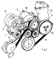
- FIG. 3 shows that drive wheels 37, 38, 39 of the auxiliary units 8 cooperate with a common belt drive 40.
Landscapes
- Engineering & Computer Science (AREA)
- Chemical & Material Sciences (AREA)
- Combustion & Propulsion (AREA)
- Mechanical Engineering (AREA)
- General Engineering & Computer Science (AREA)
- Cylinder Crankcases Of Internal Combustion Engines (AREA)
- Cooling, Air Intake And Gas Exhaust, And Fuel Tank Arrangements In Propulsion Units (AREA)
- Shafts, Cranks, Connecting Bars, And Related Bearings (AREA)
Abstract
Description
- Fig.1
- eine Schrägansicht von seitlich oben auf eine Brennkraftmaschine mit einem erfindungsgemäßen Träger,
- Fig. 2
- eine Schrägansicht von seitlich unten auf den Träger gemäß Fig.1,
- Fig.3
- eine Schrägansicht von seitlich oben auf mit dem Träger verbundene Nebenaggregate der Brennkraftmaschine.
Claims (12)
- Träger für ein Nebenaggregat einer Brennkraftmaschine, der zur Führung eines Betriebsmediums der Brennkraftmaschine ausgebildet ist, dadurch gekennzeichnet, daß der beispielsweise mehrere Nebenaggregate (8) aufnehmende Träger (7) mit einem Gehäuse (Kurbelgehäuse 6) der Brennkraftmaschine (1) verbunden ist und zur Führung von Kühlflüssigkeit vorzugsweise von einem Zylindergehäuse (4,5) zu einem Kühler für besagte Kühlflüssigkeit ausgebildet.
- Träger für eine Brennkraftmaschine mit einem Gehäuse, das gegenüberliegende Zylinderreihen mit Zylindergehäusen aufweist nach Anspruch 1, dadurch gekennzeichnet, daß der Träger (7) zumindest abschnittsweise zwischen den Zylindergehäusen (4,5) verläuft und Anschlußstutzen (10,11) für Rohrleitungen (12,13) besitzt, die zwischen den Anschlußstutzen (10,11 ) und den Zylindergehäusen (4,5) verlegt sind, wobei die Anschlußstutzen (10,11 ) als Eingänge (14,15) für Kühlwasser aus den Zylindergehäuse (4,5) ausgebildet sind, welches Kühlwasser über einen Kanal (16) im Träger (7) an einen Ausgang (17) gelangt.
- Träger nach Anspruch 2, dadurch gekennzeichnet, daß Enden (18,19) der Anschlußstutzen (10,11 ) in etwa quer zu einer Längsmittelebene (A-A) der Brennkraftmaschine (1) ausgerichtet sind.
- Träger nach Anspruch 2, dadurch gekennzeichnet, daß die Rohrleitungen (12,13) in etwa quer zur Längsmittelebene (A-A) der Brennkraftmaschine (1) ausgerichtet sind.
- Träger nach Anspruch 2, dadurch gekennzeichnet, daß beabstandet zu den Anschlußstutzen (11,12) am Träger (7) ein Querabschnitt (20) mit einem ersten Querarm (21) und einem zweiten Querarm (22) verlaufen, wobei wenigstens ein Querarm (22) den Ausgang (17) umfaßt.
- Träger nach einem oder mehreren der vorangehenden Ansprüche, dadurch gekennzeichnet, daß der Querabschnitt (20) mit Aufnahmen für (23,24,25) mehrere Nebenaggregate (8), wie Lichtmaschine (26), Klimakompressor (27), Lenkhilfepumpe (28)) oder dergl. versehen ist.
- Träger nach Anspruch 6, dadurch gekennzeichnet, daß die Aufnahmen (23,24,25) mit Öffnungen (29) zur Befestigung der Nebenaggregate (8) versehen sind.
- Träger nach den Ansprüchen 6 und 7, dadurch gekennzeichnet, daß die Aufnahmen (23,24,25) an Gehäuse der Nebenaggregate (8) angepaßte Formabschnitte (30,31,32) aufweisen.
- Träger nach einem oder mehreren der vorangehenden Ansprüche, dadurch gekennzeichnet, daß zumindest der zweite Querarm (22) lösbar ausgeführt.
- Träger nach Anspruch 9, dadurch gekennzeichnet, daß der Querarm (22) an eine Trennebene (34) eines Mittelstücks (33) des Querabschnitts (20) herangeführt ist.
- Träger nach einem oder mehreren der vorangehenden Ansprüche, dadurch gekennzeichnet, daß der Träger (8) zur Kühlwasserführung als hohlkörperartiges Gußteil ausgebildet ist.
- Träger nach einem oder mehreren der vorangehenden Ansprüche, dadurch gekennzeichnet, daß die Nebenaggregate (8) Antriebsräder (37,38,39) aufweisen, die mit einem gemeinsamen Umschlingungstrieb (40) zusammenwirken.
Applications Claiming Priority (2)
| Application Number | Priority Date | Filing Date | Title |
|---|---|---|---|
| DE19942275 | 1999-09-04 | ||
| DE19942275A DE19942275A1 (de) | 1999-09-04 | 1999-09-04 | Träger für ein Nebenaggregat einer Brennkraftmaschine |
Publications (3)
| Publication Number | Publication Date |
|---|---|
| EP1081355A2 true EP1081355A2 (de) | 2001-03-07 |
| EP1081355A3 EP1081355A3 (de) | 2002-04-10 |
| EP1081355B1 EP1081355B1 (de) | 2007-05-30 |
Family
ID=7920825
Family Applications (1)
| Application Number | Title | Priority Date | Filing Date |
|---|---|---|---|
| EP00116736A Expired - Lifetime EP1081355B1 (de) | 1999-09-04 | 2000-08-03 | Träger für ein Nebenaggregat einer Brennkraftmaschine |
Country Status (5)
| Country | Link |
|---|---|
| US (1) | US6435157B1 (de) |
| EP (1) | EP1081355B1 (de) |
| JP (1) | JP2001090547A (de) |
| DE (2) | DE19942275A1 (de) |
| ES (1) | ES2284438T3 (de) |
Cited By (2)
| Publication number | Priority date | Publication date | Assignee | Title |
|---|---|---|---|---|
| EP2402573A4 (de) * | 2009-02-25 | 2017-01-25 | Nippon Thermostat Co., Ltd. | Kühlwasserleitungsvorrichtung für einen verbrennungsmotor |
| EP3546721A1 (de) * | 2018-03-30 | 2019-10-02 | Austro Engine GmbH | Verbrennungskraftmaschine |
Families Citing this family (5)
| Publication number | Priority date | Publication date | Assignee | Title |
|---|---|---|---|---|
| DE10160882A1 (de) * | 2001-12-12 | 2003-06-26 | Volkswagen Ag | Brennkraftmaschine mit Steuertrieb |
| US6945199B2 (en) * | 2003-09-24 | 2005-09-20 | Hayes Lemmerz International, Inc. | Engine coolant crossover assembly |
| DE102005057709A1 (de) * | 2005-12-02 | 2007-06-06 | Audi Ag | Brennkraftmaschine mit einem am Zylinderblock angeordneten Nebenaggregateträger |
| CN103277183B (zh) * | 2013-06-03 | 2015-05-13 | 南车戚墅堰机车有限公司 | 新型v型柴油机冷却水出水管路结构 |
| EP3411252B1 (de) * | 2016-02-01 | 2023-04-05 | Cummins, Inc. | Halteklammern mit luftstromkanälen für zubehör |
Citations (1)
| Publication number | Priority date | Publication date | Assignee | Title |
|---|---|---|---|---|
| DE3341119C1 (de) | 1983-11-12 | 1985-06-20 | Dr.Ing.H.C. F. Porsche Ag, 7000 Stuttgart | Tragarm fuer eine Brennkraftmaschine |
Family Cites Families (19)
| Publication number | Priority date | Publication date | Assignee | Title |
|---|---|---|---|---|
| US3730147A (en) * | 1971-10-29 | 1973-05-01 | Gen Motors Corp | Engine accessory arrangement |
| AT380067B (de) | 1980-01-24 | 1986-04-10 | List Hans | Hilfsgeraetebaugruppe fuer eine wassergekuehlte brennkraftmaschine |
| JPH07111146B2 (ja) * | 1989-02-08 | 1995-11-29 | 日産自動車株式会社 | 内燃機関のチェーンカバー装置 |
| JP2507024B2 (ja) * | 1989-02-17 | 1996-06-12 | 日産自動車株式会社 | エンジンのケ―シング装置 |
| JPH0351110U (de) * | 1989-09-26 | 1991-05-17 | ||
| JP2530308Y2 (ja) * | 1990-06-05 | 1997-03-26 | マツダ株式会社 | V型エンジンの冷却水通路構造 |
| US5125376A (en) * | 1991-09-25 | 1992-06-30 | Navistar International Transportation Corp. | Modular accessory mounting apparatus for heavy duty engines |
| DE4214799C2 (de) | 1992-05-04 | 2002-08-14 | Deutz Ag | Dieselbrennkraftmaschine |
| EP0811756B1 (de) * | 1993-10-29 | 2001-08-01 | Yamaha Hatsudoki Kabushiki Kaisha | Viertakt-Brennkraftmaschine |
| DE4433247A1 (de) | 1994-09-19 | 1996-03-28 | Motoren Werke Mannheim Ag | Kombinationsgehäuse |
| US5503118A (en) * | 1995-05-23 | 1996-04-02 | Hollis; Thomas J. | Integral water pump/engine block bypass cooling system |
| DE19681509B4 (de) * | 1995-07-21 | 2009-04-23 | Wärtsilä Finland Oy | Verbrennungskraftmaschine |
| DE19543350C1 (de) * | 1995-11-21 | 1996-11-14 | Daimler Benz Ag | Aggregateträger für eine Brennkraftmaschine |
| DE19635534C2 (de) * | 1996-03-28 | 1998-07-02 | Daimler Benz Ag | Steuergehäusedeckel für eine Brennkraftmaschine |
| US5666930A (en) * | 1996-04-18 | 1997-09-16 | General Motors Corporation | Structural throttle body mount |
| DE19633485B4 (de) * | 1996-08-20 | 2004-11-18 | Dr.Ing.H.C. F. Porsche Ag | Flüssigkeitsgekühlte Brennkraftmaschine |
| DE19732370A1 (de) | 1997-07-28 | 1999-02-04 | Volkswagen Ag | Nebenaggregatemodul für eine Brennkraftmaschine |
| JP2000145452A (ja) * | 1998-11-11 | 2000-05-26 | Yamaha Motor Co Ltd | エンジンの冷却水吐出構造 |
| US6109221A (en) * | 1999-02-17 | 2000-08-29 | Kohler Co. | Engine with integral coolant pump |
-
1999
- 1999-09-04 DE DE19942275A patent/DE19942275A1/de not_active Ceased
-
2000
- 2000-08-03 DE DE50014361T patent/DE50014361D1/de not_active Expired - Lifetime
- 2000-08-03 EP EP00116736A patent/EP1081355B1/de not_active Expired - Lifetime
- 2000-08-03 ES ES00116736T patent/ES2284438T3/es not_active Expired - Lifetime
- 2000-09-01 JP JP2000265751A patent/JP2001090547A/ja not_active Withdrawn
- 2000-09-05 US US09/654,883 patent/US6435157B1/en not_active Expired - Fee Related
Patent Citations (1)
| Publication number | Priority date | Publication date | Assignee | Title |
|---|---|---|---|---|
| DE3341119C1 (de) | 1983-11-12 | 1985-06-20 | Dr.Ing.H.C. F. Porsche Ag, 7000 Stuttgart | Tragarm fuer eine Brennkraftmaschine |
Cited By (2)
| Publication number | Priority date | Publication date | Assignee | Title |
|---|---|---|---|---|
| EP2402573A4 (de) * | 2009-02-25 | 2017-01-25 | Nippon Thermostat Co., Ltd. | Kühlwasserleitungsvorrichtung für einen verbrennungsmotor |
| EP3546721A1 (de) * | 2018-03-30 | 2019-10-02 | Austro Engine GmbH | Verbrennungskraftmaschine |
Also Published As
| Publication number | Publication date |
|---|---|
| EP1081355B1 (de) | 2007-05-30 |
| EP1081355A3 (de) | 2002-04-10 |
| DE50014361D1 (de) | 2007-07-12 |
| ES2284438T3 (es) | 2007-11-16 |
| DE19942275A1 (de) | 2001-03-15 |
| JP2001090547A (ja) | 2001-04-03 |
| US6435157B1 (en) | 2002-08-20 |
Similar Documents
| Publication | Publication Date | Title |
|---|---|---|
| EP0232467A2 (de) | Mehrzylindrige Brennkraftmaschine | |
| EP1368562A1 (de) | Zylinderkurbelgehäuse für eine flüssigkeitsgekühlte Brennkraftmaschine | |
| DE19600566C1 (de) | Zylinderkurbelgehäuse einer mehrzylindrigen Brennkraftmaschine | |
| DE102004052788A1 (de) | Zylinderkopfdichtung zum Einsatz in einer Brennkraftmaschine und damit ausgerüstete Brennkraftmaschine | |
| EP0952329B1 (de) | Brennkraftmaschine mit einem integrierten Front-End | |
| EP1081355B1 (de) | Träger für ein Nebenaggregat einer Brennkraftmaschine | |
| EP1284342B1 (de) | Ölauffangvorrichtung für eine Brennkraftmaschine, insbesondere für einen Boxermotor | |
| EP0668440B1 (de) | Brennkraftmaschine | |
| DE1294737B (de) | Luftgekuehlte Brennkraftmaschine | |
| DE69427877T2 (de) | Viertakt-Brennkraftmaschine | |
| DE102004015487A1 (de) | Brennkraftmaschine mit Abgasrückführung | |
| EP0515925B1 (de) | Zylinderkopf für eine Brennkraftmaschine | |
| EP1024276B1 (de) | Hubkolben-Brennkraftmaschine | |
| DE102012022942A1 (de) | Verbrennungskraftmaschine für einen Kraftwagen | |
| EP1709307B1 (de) | Kühlmittelpumpenanordnung für eine brennkraftmaschine | |
| DE4218145C1 (en) | IC engine turbocharging system - has two part housing with water jacket within to allow circulation of cooling water around turbine | |
| DE102004061684B4 (de) | Kurbelwellenlager für eine Brennkraftmaschine | |
| EP0476286A1 (de) | Kapselung der Verbrennungskraftmaschine in einem Nutzfahrzeug | |
| DE102008013677B4 (de) | Kühlmediumpumpe als integraler Bestandteil einer die Brennkraftmaschine lagernden Konsole | |
| DE102005057709A1 (de) | Brennkraftmaschine mit einem am Zylinderblock angeordneten Nebenaggregateträger | |
| DE10101136C1 (de) | Hubkolbenbrennkraftmaschine | |
| EP1253310B1 (de) | Wassergekühlter Zylinderkopf für eine Brennkraftmaschine | |
| EP0449129A1 (de) | Brennkraftmaschine | |
| AT413740B (de) | Kurbelgehäuse | |
| DE10101227C1 (de) | Hubkolbenbrennkraftmaschine und Kurbelwelle hierfür |
Legal Events
| Date | Code | Title | Description |
|---|---|---|---|
| PUAI | Public reference made under article 153(3) epc to a published international application that has entered the european phase |
Free format text: ORIGINAL CODE: 0009012 |
|
| AK | Designated contracting states |
Kind code of ref document: A2 Designated state(s): AT BE CH CY DE DK ES FI FR GB GR IE IT LI LU MC NL PT SE Kind code of ref document: A2 Designated state(s): DE ES FR GB IT |
|
| AX | Request for extension of the european patent |
Free format text: AL;LT;LV;MK;RO;SI |
|
| PUAL | Search report despatched |
Free format text: ORIGINAL CODE: 0009013 |
|
| AK | Designated contracting states |
Kind code of ref document: A3 Designated state(s): AT BE CH CY DE DK ES FI FR GB GR IE IT LI LU MC NL PT SE |
|
| AX | Request for extension of the european patent |
Free format text: AL;LT;LV;MK;RO;SI |
|
| RIC1 | Information provided on ipc code assigned before grant |
Free format text: 7F 02B 67/06 A, 7F 02B 63/00 B, 7F 01P 11/04 B, 7F 02B 75/24 B |
|
| 17P | Request for examination filed |
Effective date: 20021010 |
|
| AKX | Designation fees paid |
Free format text: DE ES FR GB IT |
|
| 17Q | First examination report despatched |
Effective date: 20050329 |
|
| GRAP | Despatch of communication of intention to grant a patent |
Free format text: ORIGINAL CODE: EPIDOSNIGR1 |
|
| GRAS | Grant fee paid |
Free format text: ORIGINAL CODE: EPIDOSNIGR3 |
|
| GRAA | (expected) grant |
Free format text: ORIGINAL CODE: 0009210 |
|
| AK | Designated contracting states |
Kind code of ref document: B1 Designated state(s): DE ES FR GB IT |
|
| REG | Reference to a national code |
Ref country code: GB Ref legal event code: FG4D Free format text: NOT ENGLISH |
|
| REF | Corresponds to: |
Ref document number: 50014361 Country of ref document: DE Date of ref document: 20070712 Kind code of ref document: P |
|
| PGFP | Annual fee paid to national office [announced via postgrant information from national office to epo] |
Ref country code: ES Payment date: 20070830 Year of fee payment: 8 |
|
| GBT | Gb: translation of ep patent filed (gb section 77(6)(a)/1977) |
Effective date: 20070815 |
|
| ET | Fr: translation filed | ||
| REG | Reference to a national code |
Ref country code: ES Ref legal event code: FG2A Ref document number: 2284438 Country of ref document: ES Kind code of ref document: T3 |
|
| PGFP | Annual fee paid to national office [announced via postgrant information from national office to epo] |
Ref country code: GB Payment date: 20070823 Year of fee payment: 8 |
|
| PGFP | Annual fee paid to national office [announced via postgrant information from national office to epo] |
Ref country code: IT Payment date: 20070824 Year of fee payment: 8 |
|
| PLBE | No opposition filed within time limit |
Free format text: ORIGINAL CODE: 0009261 |
|
| STAA | Information on the status of an ep patent application or granted ep patent |
Free format text: STATUS: NO OPPOSITION FILED WITHIN TIME LIMIT |
|
| PGFP | Annual fee paid to national office [announced via postgrant information from national office to epo] |
Ref country code: FR Payment date: 20070812 Year of fee payment: 8 |
|
| 26N | No opposition filed |
Effective date: 20080303 |
|
| GBPC | Gb: european patent ceased through non-payment of renewal fee |
Effective date: 20080803 |
|
| REG | Reference to a national code |
Ref country code: FR Ref legal event code: ST Effective date: 20090430 |
|
| REG | Reference to a national code |
Ref country code: FR Ref legal event code: TP |
|
| PG25 | Lapsed in a contracting state [announced via postgrant information from national office to epo] |
Ref country code: FR Free format text: LAPSE BECAUSE OF NON-PAYMENT OF DUE FEES Effective date: 20080901 Ref country code: IT Free format text: LAPSE BECAUSE OF NON-PAYMENT OF DUE FEES Effective date: 20080803 |
|
| REG | Reference to a national code |
Ref country code: ES Ref legal event code: FD2A Effective date: 20080804 |
|
| REG | Reference to a national code |
Ref country code: FR Ref legal event code: CD |
|
| PG25 | Lapsed in a contracting state [announced via postgrant information from national office to epo] |
Ref country code: GB Free format text: LAPSE BECAUSE OF NON-PAYMENT OF DUE FEES Effective date: 20080803 |
|
| PG25 | Lapsed in a contracting state [announced via postgrant information from national office to epo] |
Ref country code: ES Free format text: LAPSE BECAUSE OF NON-PAYMENT OF DUE FEES Effective date: 20080804 |
|
| PGFP | Annual fee paid to national office [announced via postgrant information from national office to epo] |
Ref country code: DE Payment date: 20190819 Year of fee payment: 20 |
|
| REG | Reference to a national code |
Ref country code: DE Ref legal event code: R071 Ref document number: 50014361 Country of ref document: DE |