EP1081076A2 - Vorrichtung und Verfahren zum Überführen eines Materialbahnstreifens - Google Patents
Vorrichtung und Verfahren zum Überführen eines Materialbahnstreifens Download PDFInfo
- Publication number
- EP1081076A2 EP1081076A2 EP00113657A EP00113657A EP1081076A2 EP 1081076 A2 EP1081076 A2 EP 1081076A2 EP 00113657 A EP00113657 A EP 00113657A EP 00113657 A EP00113657 A EP 00113657A EP 1081076 A2 EP1081076 A2 EP 1081076A2
- Authority
- EP
- European Patent Office
- Prior art keywords
- strip
- web
- material web
- transfer
- path
- Prior art date
- Legal status (The legal status is an assumption and is not a legal conclusion. Google has not performed a legal analysis and makes no representation as to the accuracy of the status listed.)
- Withdrawn
Links
- 239000000463 material Substances 0.000 title claims abstract description 186
- 238000000034 method Methods 0.000 title claims abstract description 29
- 238000012546 transfer Methods 0.000 claims abstract description 81
- 238000012545 processing Methods 0.000 claims abstract description 33
- 238000001035 drying Methods 0.000 claims description 25
- 238000007664 blowing Methods 0.000 claims description 5
- 238000011144 upstream manufacturing Methods 0.000 claims description 5
- 238000007600 charging Methods 0.000 claims description 3
- 238000011143 downstream manufacturing Methods 0.000 claims description 2
- 239000007788 liquid Substances 0.000 claims description 2
- 238000005461 lubrication Methods 0.000 claims 1
- 238000004519 manufacturing process Methods 0.000 description 7
- 238000005520 cutting process Methods 0.000 description 5
- 230000002093 peripheral effect Effects 0.000 description 5
- 238000010586 diagram Methods 0.000 description 4
- 238000011161 development Methods 0.000 description 2
- 238000013461 design Methods 0.000 description 1
- 238000007786 electrostatic charging Methods 0.000 description 1
- 239000002985 plastic film Substances 0.000 description 1
- 229920006255 plastic film Polymers 0.000 description 1
- 238000012958 reprocessing Methods 0.000 description 1
- 238000003892 spreading Methods 0.000 description 1
- 239000004753 textile Substances 0.000 description 1
Images




Classifications
-
- D—TEXTILES; PAPER
- D21—PAPER-MAKING; PRODUCTION OF CELLULOSE
- D21G—CALENDERS; ACCESSORIES FOR PAPER-MAKING MACHINES
- D21G9/00—Other accessories for paper-making machines
- D21G9/0063—Devices for threading a web tail through a paper-making machine
- D21G9/0072—Devices for threading a web tail through a paper-making machine using at least one rope
Definitions
- the invention relates to a device for transferring of a strip of material within one Machine for the production and / or processing of a Material web, according to the preamble of claim 1 and a method for transferring a strip of material within a manufacturing machine and / or processing a material web, according to the preamble of claim 21.
- the device includes one along the web path relocatable recording head with a receiving opening, which can be pressurized with a vacuum is around a cut off from an edge of a material web, also referred to as threading strips Material web strips or the material web with their suck in full width and with a the suction hose connected from the Lead out the path of the web.
- This makes it possible the material web strip within a web production and / or web processing machine from a takeover area into a transfer area along the web path at a speed to convict that is less than the speed the material web strip itself during of the transfer process.
- the outside of the web head guided protrudes very much far into the path, so that the still not inserted part of the Strip of material within the path of the web is led.
- the recording head is therefore very wide, resulting in a strong one-sided weight load and thus to an increased vibration or Pendulum susceptibility leads.
- the deflection of the material web strip can also cause a web congestion within of the recording head.
- the invention is therefore based on the object a device and a method of the aforementioned Way of creating a safe flyover of the material strip at preferably guaranteed light weight of the recording head can be.
- the Transfer device is characterized by that the recording head is guided such that the Receiving opening - seen in the machine direction Web path is laterally offset and that in the takeover area a first strip guiding device to relocate the material web strip out of the path in the direction of the receiving opening and / or in the transfer area a second strip guide for guiding the Material strip in the direction of and along the further web travel paths are / is provided. Because of With this configuration, a recording head can be realized be of only a small width and thus preferably none, but at least only a small one Has susceptibility to vibration and pendulum, so that a safe transfer of the web of material from the takeover area to the transfer area can be guaranteed.
- the receiving opening can at least during the takeover and / or handover of the material strip completely outside the path of the web. It is also possible that an edge region of the receiving opening in Web path is arranged. During the transfer process can guide the recording head like this be designed so that the receiving opening completely is out of the way or during of the entire transfer / threading process with an edge area protruding into the web path.
- the recording head is advantageous Embodiment performed outside the web path.
- Receiving opening can guide the strip of material designed within the recording head be that only a slight deflection of the web of material is necessary to this in particular lead out of the side of the machine, for example through one with the receiving opening connected suction hose.
- a web congestion within of the recording head or in that of the recording head - seen in the direction of web travel - downstream Suction hose or a web break can come in handy be excluded.
- a strip guide In a first embodiment of the transfer device it is intended that only in Takeover area arranged a strip guide is that, for example, freely in one Basement of the machine-running strip of material right up to the receiving opening, at least but in the direction of the side to the railway path receiving opening arranged in a takeover position leads, causing the retraction of the web of material into the receiving opening in easier Is possible, for example, by applying a vacuum the receiving opening.
- the first strip guide and additionally in Transfer area the second strip guide is arranged, the incoming, from the recording head material web strips guided outside the web path recorded in the transfer area, see above that a defined forwarding of the material web strip in a subsequent processing station, for example the machine can be done.
- second strip guide device assigned to the transfer area intended.
- the first strip guiding device at least comprises two deflection elements, the - in the direction of rotation the strip of material seen in one Are spaced from each other.
- the deflection elements can, for example, of a rotatable or drivable roller be formed.
- the deflecting element from a correspondingly curved Area to be formed, at least during the transfer of the material web strip is fixed.
- at least one Deflecting element from one during the transfer deflection rod arranged in a stationary manner is formed, over which the material web strip are guided can.
- the contact area of the material web strip on the deflecting rod is preferably small, so that which by relative movement between the fixed Deflecting rod and the machine speed having material web strips on these acting Frictional forces are low.
- the fixed deflection elements can be air / gas lubricated be equipped.
- the respective deflection element points out, for example, in his come into contact with the material web strip Area with a pressurized, gaseous Medium pressurized openings so that a Gas cushion between the deflection element and the material web strip can be formed.
- At least a deflection element can be moved into the web path trained so that, for example, in normal operation the machine, so if there is no transfer of the Material web is required, the deflecting element removed from the transport area of the material web can be.
- the deflection element is, for example pivoted.
- a second accordingly inclined deflection element allows parallel offset of the material web strip to the web path.
- both deflecting elements are inclined so that - in the direction of travel the strip of material seen to the pick-up head dump and that the lower of the two in one vertical spacing from each other stands more obliquely than the upper deflection element, to the unequal inlet and outlet angles of the Compensate web strip on the deflection elements.
- the lateral offset of the material web strip can range from 10 mm to 500 mm. Of course, with an appropriate arrangement and design of the deflection elements If necessary, an offset of more than 500 mm can be realized. In an advantageous embodiment is the distance between the receiving opening of the pick-up head and the web path 80 mm up to 350 mm, in particular 150 mm to 200 mm.
- a method is also proposed to solve the problem, having the features of claim 21.
- the method provides that the strip of material in the takeover area from the side Web path out and during the transfer process at least a section with a side Offset to the path of the web.
- the transfer device described below 1 is general for transferring one of one Material web separated threading strip or a narrow web of material with all of it Width within a machine for manufacturing and / or processing of a material web can be used.
- the following is therefore generally a strip of material web spoken.
- the material web can for example a paper, cardboard, textile web, Plastic film, fleece or non-woven. Purely in the following it is assumed as an example that this is a paper machine, in who produces and / or processes a paper web, for example, refined, coated, printed or the like.
- Transfer device 1 comprises at least one Recording device 3, the at least one recording head 5 ( Figure 5) with at least one receiving opening 7 includes.
- the recording head 5 is a suction head 9 formed, on which a vacuum actable suction hose 11 is attached, through the one inserted into the receiving opening 7 or sucked in material web strip continued and for example a reprocessing facility can be supplied.
- the recording head 5 is by means of one in the figures Guide device not shown along a web path of the material web strip relocatable.
- the guide device includes this embodiment with the recording head 5 connectable, in the figures with a dashed line shown ropes 13, which are guided over pulleys 15 and can be moved by means of a drive.
- the structure and function of the reception facility 3 and in particular the recording head 5 go out WO 98/56701, the content of which is the subject this description is made.
- the recording head 5 Because of this configuration of the receiving device 3, which feeds the web strip and during the transfer or threading process leads, the recording head 5 with a be shifted significantly lower speed, than that drawn into the receiving opening 7 Material web strip itself, its speed the machine speed during the transfer process can correspond. During the transfer the strip of material web moves relatively opposite the receiving head 5 of the receiving device 3. With the help of the receiving device 3 can especially at high machine speeds safe threading of the material web strip be guaranteed in the web path.
- the strip of material is, for example over rollers, through roller presses, over Device areas, above / through treatment facilities, guided over / through measuring devices and / or on belts, their arrangement within the machine the route the web of material during normal operation the machine.
- the web path can but only extend over a distance, which is located between two processing stations, can also be a free path.
- FIGS Takeover process described in which way and with what means the strip of material in a takeover area from the receiving device 3 detected and guided in the direction of a transfer area becomes.
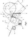
- Figure 1 shows a section of an embodiment a paper machine in side view, namely one between a first processing station 19, formed here by a dry group and in the machine direction (arrow 21) seen - downstream, second processing station 23 located takeover area 17.
- first processing station 19 From the first processing station 19 is the last one Drying cylinder 25 recognizable over its circumferential surface one in the following generally as a material web 27 designated paper web together with one Conveyor belt 29 is guided.
- the conveyor belt 29 is in the drain area of the drying cylinder 25 a deflection roller 30 separated from the material web 27, the vertical in the representation of Figure 1 down, for example into a basement the paper machine.
- a perimeter area of the drying cylinder 25 in which the material web 27 lies freely on the drying cylinder is one also known as a tip cutter 31 assigned, with the help of at least in the edge region of the material web 27 a material web strip 33 is separable.
- the cutting device 31 is on one across the entire width the material web 27 extending traverse 34 attached and along this cross to the machine direction (Arrow 21) relocatable, so that the width of the material web strip 33 to the width of the Material web 27 can be enlarged.
- the structure of the Cutting device 31 is known in principle, so that this will not be discussed in more detail here.
- a slit-shaped can be acted upon with a vacuum Suction funnel 35 arranged with a Vacuum can be applied and is transverse to the machine direction at least across the width of the from the drying cylinder 25 running material web strip 33 extends.
- the suction funnel 35 sucks the material web strip 33 and possibly the remaining path. This will make the web of material 33 when leading away, for example to a Processing device, stretched in the longitudinal direction.
- the drying cylinder 25 is a scraper device 37 assigned, which here includes a deflector 39, which is used in the event of a web break or during commissioning the paper machine at least the circumference of the drying cylinder 25 adhering material web strips 33 detach from the drying cylinder 25 and in the direction of the suction funnel located below 35 redirect.
- a deflector 39 which is used in the event of a web break or during commissioning the paper machine at least the circumference of the drying cylinder 25 adhering material web strips 33 detach from the drying cylinder 25 and in the direction of the suction funnel located below 35 redirect.
- the baffle 39 over the entire Width of the material web 27 extends or that several side plates arranged side by side are provided are.
- the takeover area 17 there is also a drivable Web guide roller 41 arranged, the part of the second Processing station 23 is in which the material web 27 should be threaded here.
- the web guide roller 41 is diagonally opposite the deflector plate 39 arranged.
- the optimal arrangement of the web guide roller 41 is selected so that in the suction funnel 35 sucked material web strip 33 this tangentially is guided on the web guide roller 41.
- the rope pulleys are at the edge of the web guide roller 41 15 for guiding and transporting the receiving device 3 serving ropes 13 freely rotatable appropriate.
- Below the scraper device 37 are further pulleys 15 arranged, such that the at least two in the direction of a double arrow 49 displaceable ropes 13 over a circumferential area attached to the web guide roller 41 Rope pulleys 15 abut.
- FIG. 12 is more schematic Top view of the material web 27 as an example the lateral offset x between the recording head 5 and the material web strip guided in the web path 33 shown.
- the train path so the path that the material web 27 during normal Operation of the machine to the left of one shown in dashed lines in FIG Level E1, on which the material web strip 33 immediately adjacent.
- the offset x is here between the middle of the material web strip 33 and the center of the receiving opening 7 of the receiving head 5 measured.
- the lateral offset x is the amount around which the material web strip 33 from the Web path must be shifted out laterally.
- the lateral offset x is in a range of 10 mm to 500 mm, preferably from 80 mm to 350 mm, in particular 150 mm to 200 mm.
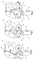
- the first strip guiding device 43 comprises a first, upper deflection element 45, which is below the Cutting device 31 and above the deflector 39 is arranged, and a second, lower deflection element 47 arranged at a distance from each other are.
- the deflection elements 45, 47 are at this embodiment of cylindrical deflecting rods educated.
- the arrangement of the upper deflection element 45 that in this embodiment is fixed in the machine chosen such that the one running off the drying cylinder 25 and preferably in the vertical direction material webs sucked down into the suction funnel 35 33 only in a preferably small Distance to the deflection element 45 is arranged.
- the lower deflection element 47 is designed to be displaceable, as indicated by a double arrow 49, and is shown in Figure 1 in two functional positions.
- the lower deflection element 47 In the first functional position the lower deflection element 47 below the deflector 39 and - in cross section through the machine seen - outside the walkway of the down expiring strip of material 33.
- the arrangement of the lower deflection element 47 is chosen so that the running material web strip 33 between the deflecting element 47 and web guide roller 41 to run safely is coming.
- the deflecting element 47 in the path of the web downward web of material strip 33 retracted, which deflects and thereby over a peripheral region of the upper deflection element 45 is created.
- the running distance of the in its second functional position arranged lower Deflection element 47 deflected strip of material 33 is indicated by dashed line 48.
- the deflection elements 45, 47 are opposite to that Takeover area 17 upstream and / or downstream Cylinders and rollers, such as the Drying cylinder 25 or the web guide roller 41, arranged inclined.
- the one Schematic horizontal view of the in Figure 1 shown transfer area 17 can be seen that the inclined towards the machine edge Deflection elements 45, 47 with respect to the horizontally arranged Web guide roller 41 different inclinations have, the lower deflecting element 47 a greater inclination with respect to the web guide roller 41 has, as the upper deflection element 45.
- the different Oblique positions of the deflection elements 45, 47 serve the non-identical feed and Run-off angle of the material web strip 33 with respect to compensate for the deflection elements 45, 47.
- the length of the deflection elements 45, 47 is less than that of the web guide roller 41.
- the deflection element 47 extends, for example only so far in the path of the material web 27 that only the one cut off at the edge of the track Material web strips 33 captured and laterally is led to the outside of the machine, in who took over the strip of material through the receiving device 3 is possible.
- the identification plate 39 only the width of the material strip 33 has to run this To guide the deflecting element 47 can also extend the deflection element 47 further into the machine.
- the receiving device 3 is already along the path of the processing station 23 shifted towards a takeover area, preferably at a speed that is clear is less than the running speed of the Webstrip 33 during the transfer Threading process.
- the processing station 23 After the material web strip 33 in the web path the processing station 23 has been threaded with the aid of the receiving device 3 rotates the same guide roller (s) that the Material web 27 with its entire width during of the normal operation of the machine the material web strip 33 in the transfer area one of the second processing station 23 third processing station, for example another drying group. Up to this The material web strip 33 of the first strip guide 43 always laterally led out of the path. After the Material web strips 33 to the third processing station is transferred, as shown in FIG. 9, the lower deflection element 47 of the first Strip guiding device 43 in the direction of an arrow 53 obliquely in their starting position (rest position) shifted back down.
- Figure 11 shows a side view of the machine Production of the material web 27 in an intermediate the transfer line or the second processing station 23 and one in the machine direction (Arrow 21) downstream processing station 55 lying transfer area 57. Same parts provided with the same reference numerals so that on the description of the previous ones Figures is referenced.
- the guide roller 61 and the conveyor belt 63 are part of a guide device 60 for the strip of material, on their function below is discussed in more detail.
- the guide roller 61 is the drying cylinder 59 - in the machine direction seen - upstream and in one direction the distance H1 measured from the path of the web Drying cylinder 59 arranged.
- the arrangement of the guide roller 61 is selected such that the material web strip 33 retracting receiving opening 7 of the receiving head 5 against that between the peripheral surface of the guide roller 61 and that running from the guide roller 61 Conveyor belt 63, run area 74 formed past can be.
- the guide device 60 is part of a second one Strip guiding device 58, with the help of which in the receiving opening 7 retracted material web strips 33 in the direction of and along the path of the railway can be led, that is, through the second Strip guiding device 58 can be the material web strip 33 transverse to the direction of web travel, the means in the direction of the center of the machine until arranged in a directly next to the path Area.
- a suction box can be located in the drain area 74 comprehensive suction device 65 may be arranged with whose help the material web strip 33 through gas-permeable conveyor belt 63 therethrough additionally sucked in and on the conveyor belt 63 can be held.
- the through the suction device 65 generated air flow is indicated by an arrow 67.
- the suction device 65 transversely to the machine direction essentially only about the Width of the strip of material, and only in Area of the receiving opening 7, and is on the peripheral surface the guide roller 61, ie where the material web strip is passed.
- the Length of the suction device 65 - in the running direction of the Material web seen - is in a first embodiment only relatively low, so that suction of the conveyor belt 65 only in the discharge area 74 takes place.
- the suction device 65 from drain area 74 to the run-up point of the Conveyor belt 63 on the drying cylinder 59. Die Length of the suction device 65 depends on the Properties of the material web and the way of operation the machine speed during of the transfer process.
- the parts of the machine will be a relatively large one free running distance of the conveyor belt 63 between the guide roller 61 and the drying cylinder 59 ensured. Furthermore, the recording head 5 becomes one certain distance essentially parallel to Running distance of that running from the guide roller 61 Conveyor belt 63 guided. This makes one sufficient large transfer route created in the applying the material web strip 33 to the Conveyor belt 63 is possible, the material web strip 33 and the conveyor belt 63 essentially have the same speed. in the At the moment of transfer, the recording head 5 is preferably at a standstill Quiet, so it will not be relocated.
- a charging device are used with the help of a electrostatic charging of the conveyor belt and / or the material web strip is possible, wherein due to the electrostatic forces of the material web strips quasi pinned to the conveyor belt is, so that a safe onward transport of the strip of material adjacent to the conveyor belt can be ensured.
- another strip knock-off device which can be assigned to the receiving head 5 are used, the in the receiving opening 7 retracted material web strips immediately in front of the receiving opening 7 this strikes out and against the conveyor belt.
- the deflection elements arranged in the takeover area 17 45, 47 guide the material web strip 33 out of the side of the machine.
- the deflecting element 47 pivoted into the web path.
- the pick-up head 5 then grips the strip of material 33 and directs him alongside the rest of the web further out of the machine. After this Transfer of the material web strip 33 into the transfer area 57 becomes the material web strip 33 then from that downstream of the transfer line Processing station gripped or drawn in, for example between the conveyor belt 63 and the peripheral surface of the drying cylinder 59.
- the length of the transfer distance within which the material web strips drawn into the receiving opening 7 33 transferred to the processing station 55 or applied to the conveyor belt 63 corresponds to that shown in FIG Embodiment in the direction of the web measured distances H1 and H2.
- first strip guide 43 and the second strip guide 58 separate facilities are. During the first strip guide 43 the deflection and deflection of the material web strip in a lateral direction from the web path, can with the help of the second strip guide 58 the material web strip guided by the receiving device 3 33 to a subsequent processing station be handed over regardless what is the distance between the outside of the Material path strips and the web path.
Landscapes
- Advancing Webs (AREA)
- Separation, Sorting, Adjustment, Or Bending Of Sheets To Be Conveyed (AREA)
- Replacement Of Web Rolls (AREA)
Abstract
Description
- Figur 1
- eine Prinzipskizze eines Teils einer Maschine zur Herstellung-/Bearbeitung einer Materialbahn in einem Übernahmebereich zwischen zwei Bearbeitungsstationen in Seitenansicht;
- Figuren 2 bis 10
- jeweils eine Prinzipskizze eines Ausführungsbeispiels einer im Übernahmebereich angeordneten Streifenleiteinrichtung in verschiedenen Funktionsstellungen und
- Figur 11
- eine Prinzipskizze einer in einem Übergabebereich der Maschine vorgesehenen zweiten Streifenleiteinrichtung in Seitenansicht;
- Figur 12
- eine Draufsicht auf einen in einem Bahnlaufweg einer Maschine im Normalbetrieb geführten Materialbahnstreifen und
- Figur 13
- eine schematische Prinzipskizze in horizontaler Sicht eines Teils der anhand von Figur 1 beschriebenen Maschine im Querschnitt.
Claims (25)
- Vorrichtung zum Überführen eines Materialbahnstreifens innerhalb einer Maschine zur Herstellung und/oder Bearbeitung einer Materialbahn (27), von einem Übernahmebereich (17) in einen Übergabebereich (57) entlang eines Bahnlaufweges, mit mindestens einer entlang des Bahnlaufweges verlagerbaren, den Materialbahnstreifen (33) während des Überführungsvorgangs führenden Aufnahmeeinrichtung (3), die mindestens einen wenigstens eine Aufnahmeöffnung (7) aufweisenden Aufnahmekopf (5) umfaßt, dadurch gekennzeichnet, daß der Aufnahmekopf (5) derart geführt ist, daß die Aufnahmeöffnung (7) -in Maschinenlaufrichtung gesehen- zum Bahnlaufweg seitlich versetzt angeordnet ist, und daß im Übernahmebereich eine erste Streifenleiteinrichtung (43) zur Verlagerung des Materialbahnstreifens aus dem Bahnlaufweg heraus in Richtung der Aufnahmeöffnung (7) und/oder im Übergabebereich (57) eine zweite Streifenleiteinrichtung (58) zur Führung des Materialbahnstreifens (33) in Richtung und entlang des weiteren Bahnlaufwegs vorgesehen sind/ist.
- Überführungsvorrichtung nach Anspruch 1, dadurch gekennzeichnet, daß der seitliche Versatz (x) in einem Bereich von 10 mm bis 500 mm, vorzugsweise von 80 mm bis 350, insbesondere von 150 mm bis 200 mm, liegt.
- Überführungsvorrichtung nach Anspruch 1 oder 2, dadurch gekennzeichnet, daß die erste Streifenleiteinrichtung (43) mindestens zwei Umlenkelemente (45,47) umfaßt, die -in Laufrichtung des Materialbahnstreifens (33) gesehen- in einem Abstand voneinander angeordnet sind und daß mindestens ein Umlenkelement (45;47) vorzugsweise eine Gasschmierung für den Materialbahnstreifen (33) aufweist.
- Überführungsvorrichtung nach einem der vorhergehenden Ansprüche, dadurch gekennzeichnet, daß mindestens ein Umlenkelement (45,47) von einer Umlenkstange gebildet ist.
- Überführungsvorrichtung nach einem der vorhergehenden Ansprüche, dadurch gekennzeichnet, daß mindestens ein Umlenkelement (47) in den Bahnlaufweg verlagerbar ausgebildet ist.
- Überführungsvorrichtung nach einem der vorhergehenden Ansprüche, dadurch gekennzeichnet, daß -in Maschinenlaufrichtung gesehen- mindestens ein Umlenkelement (45,47) gegenüber im Übernahmebereich (17) angeordneten und/oder dem Übernahmebereich (17) vorgeordneten und/oder nachgeordneten Walzen, Zylindern oder dergleichen geneigt angeordnet ist.
- Überführungsvorrichtung nach einem der vorhergehenden Ansprüche, dadurch gekennzeichnet, daß die Umlenkelemente (45,47) -in vertikaler Richtung gesehen- unterhalb eines Auslaufs (Trockenzylinder (25)) einer dem Übernahmebereich (17) vorgeordneten Bearbeitungsstation (19) angeordnet sind.
- Überführungsvorrichtung nach einem der vorhergehenden Ansprüche, dadurch gekennzeichnet, daß die Umlenkelemente (45,47) -in vertikaler Richtung gesehen- oberhalb einer Bahnleitwalze (41) angeordnet sind.
- Überführungsvorrichtung nach einem der vorhergehenden Ansprüche, dadurch gekennzeichnet, daß -in vertikaler Richtung gesehen- unterhalb der Umlenkelemente (45,47) ein mit einem Unterdruck beaufschlagbarer Absaugtrichter (35) für den Materialbahnstreifen (33) angeordnet ist.
- Überführungsvorrichtung nach einem der vorhergehenden Ansprüche, dadurch gekennzeichnet, daß die Anordnung der Bahnleitwalze (41) und des Absaugtrichters (35) so gewählt ist, daß bei in den Absaugtrichter (35) eingesaugtem Materialbahnstreifen (33) dieser im wesentlichen tangential an der Bahnleitwalze (41) oder im wesentlichen tangential zur Bahnleitwalze (41) geführt ist.
- Überführungsvorrichtung nach einem der vorhergehenden Ansprüche, dadurch gekennzeichnet, daß zumindest der die Aufnahmeöffnung (7) aufweisende Teil des Aufnahmekopfs (5) bis in den Freiraum zwischen der Bahnleitwalze (41) und dem Absaugtrichter (35) verlagerbar ist.
- Überführungsvorrichtung nach einem der vorhergehenden Ansprüche, dadurch gekennzeichnet, daß dem Trockenzylinder (25) eine Schabereinrichtung (37) zugeordnet ist, die mindestens ein Abweisblech (39) zur Führung des vom Umfang des Trockenzylinders (25) abgelösten Materialbahnstreifens (33) aufweist.
- Überführungsvorrichtung nach einem der vorhergehenden Ansprüche, dadurch gekennzeichnet, daß das Abweisblech (39) derart ausgebildet ist, daß es den Materialbahnstreifen (33) über das eine, sich in einer Ruheposition befindliche Umlenkelement (47) leitet.
- Überführungsvorrichtung nach einem der vorhergehenden Ansprüche, dadurch gekennzeichnet, daß die zweite Streifenleiteinrichtung (58) eine Leiteinrichtung (60) einer dem Übergabebereich (57) nachgeordneten Bearbeitungsstation (55) mit mindestens einem über die Leiteinrichtung (60) geführten Transportband (63) umfaßt.
- Überführungsvorrichtung nach einem der vorhergehenden Ansprüche, dadurch gekennzeichnet, daß das Transportband (63) gasdurchlässig ausgebildet ist.
- Überführungsvorrichtung nach einem der vorhergehenden Ansprüche, dadurch gekennzeichnet, daß in dem Bereich, in dem das Transportband (63) von der Leiteinrichtung (60) abläuft, auf der dem Materialbahnstreifen (33) abgewandten Seite des Transportbandes (63) eine Saugeinrichtung (65) angeordnet ist.
- Überführungsvorrichtung nach einem der vorhergehenden Ansprüche, dadurch gekennzeichnet, daß auf der dem Transportband (63) abgewandten Seite des Materialbahnstreifens (33) eine Blaseinrichtung zur Beaufschlagung des Materialbahnstreifens (33) mit einem flüssigen oder gasförmigen Mediumstrom vorgesehen ist.
- Überführungsvorrichtung nach einem der vorhergehenden Ansprüche, dadurch gekennzeichnet, daß die zweite Streifenleiteinrichtung (58) eine der Aufnahmeöffnung (7) des Aufnahmekopfs (5) zuordenbare Streifen-Abschlagvorrichtung mit mindestens einem in Richtung auf das Transportband (63) verlagerbaren Abschlagelement umfaßt.
- Überführungsvorrichtung nach einem der vorhergehenden Ansprüche, dadurch gekennzeichnet, daß die zweite Streifenleiteinrichtung eine Aufladungseinrichtung zur elektrostatischen Aufladung des Transportbandes (63) und/oder des Materialbahnstreifens (33) umfaßt.
- Überführungsvorrichtung nach einem der vorhergehenden Ansprüche, dadurch gekennzeichnet, daß der Leiteinrichtung (60) -in Maschinenlaufrichtung gesehen- eine Bearbeitungswalze (Trockenzylinder (59)) nachgeordnet ist, und daß der Abstand zwischen der Leiteinrichtung (60) und der Bearbeitungswalze derart groß ist, daß eine ausreichend lange Übergabestrecke (Σ H1,H2) und eine Möglichkeit zur Anordnung der Seilscheiben (15) besteht.
- Verfahren zum Überführen eines Materialbahnstreifens innerhalb einer Maschine zur Herstellung und/oder Bearbeitung einer Materialbahn, von einem Übernahmebereich in einen Übergabebereich im wesentlichen entlang eines Bahnlaufweges, insbesondere mit Hilfe einer Vorrichtung nach einem der vorhergehenden Ansprüche 1 bis 20, dadurch gekennzeichnet, daß der Materialbahnstreifen im Übernahmebereich seitlich aus dem Bahnlaufweg herausgeführt und während des Überführungsvorgangs zumindest eine Teilstrecke mit seitlichem Versatz zum Bahnlaufweg geführt wird.
- Verfahren nach Anspruch 21, dadurch gekennzeichnet, daß die Zurückführung des Materialbahnstreifens in den Bahnlaufweg bei der Übergabe oder erst nach der Übergabe an eine dem Übergabebereich nachgeordnete Bearbeitungsstation selbständig erfolgt.
- Verfahren nach einem der vorhergehenden Ansprüche, dadurch gekennzeichnet, daß der Materialbahnstreifen vom Randbereich der Materialbahn abgetrennt ist und daß der Materialbahnstreifen erst dann auf Materialbahnbreite vergrößert wird, nachdem er in den Bahnlaufweg zurückgeführt worden ist.
- Verfahren nach einem der vorhergehenden Ansprüche, dadurch gekennzeichnet, daß der Materialbahnstreifen in Längsrichtung gespannt ist, bevor er im Übernahmebereich schräg zu seiner Laufrichtung aus dem Bahnlaufweg herausgeführt wird.
- Verfahren nach einem der vorhergehenden Ansprüche, dadurch gekennzeichnet, daß die Übergabe des Materialbahnstreifens von einem Aufnahmekopf einer entlang des Bahnlaufweges verlagerbaren Aufnahmeeinrichtung an eine nachgeordnete Bearbeitungsstation ausgehend von einer neben dem Bahnlaufweg verlaufenden Spur erfolgt und daß dort die Zurückführung des Materialbahnstreifens in den Bahnlaufweg ohne weitere Eingriffe selbsttätig erfolgt, indem der Materialbahnstreifen im Übernahmebereich wieder in den Bahnlaufweg zurückgeführt wird, wodurch auch der den Übergabebereich durchlaufende Teil des Materialbahnstreifens weiter nach Innen in den Bahnlaufweg wandert.
Applications Claiming Priority (2)
| Application Number | Priority Date | Filing Date | Title |
|---|---|---|---|
| DE1999141426 DE19941426A1 (de) | 1999-08-30 | 1999-08-30 | Vorrichtung und Verfahren zum Überführen eines Materialbahnstreifens |
| DE19941426 | 1999-08-30 |
Publications (2)
| Publication Number | Publication Date |
|---|---|
| EP1081076A2 true EP1081076A2 (de) | 2001-03-07 |
| EP1081076A3 EP1081076A3 (de) | 2002-09-18 |
Family
ID=7920269
Family Applications (1)
| Application Number | Title | Priority Date | Filing Date |
|---|---|---|---|
| EP00113657A Withdrawn EP1081076A3 (de) | 1999-08-30 | 2000-06-28 | Vorrichtung und Verfahren zum Überführen eines Materialbahnstreifens |
Country Status (2)
| Country | Link |
|---|---|
| EP (1) | EP1081076A3 (de) |
| DE (1) | DE19941426A1 (de) |
Family Cites Families (6)
| Publication number | Priority date | Publication date | Assignee | Title |
|---|---|---|---|---|
| SE305123B (de) * | 1967-05-30 | 1968-10-14 | Svenska Flaektfabriken Ab | |
| CH659035A5 (de) * | 1980-05-06 | 1986-12-31 | Walter Spengler | Verfahren zum zusammentragen von buendeln aus elektrisch isolierenden bogenfoermigen haelftig gefalteten substratmaterialien. |
| DE3328162C2 (de) * | 1983-08-04 | 1986-02-20 | J.M. Voith Gmbh, 7920 Heidenheim | Papiermaschine |
| DE4220682C1 (de) * | 1992-06-24 | 1993-12-23 | Voith Gmbh J M | Vorrichtung zum Überführen einer Faserstoffbahn |
| DE19516655C2 (de) * | 1995-05-05 | 2000-07-06 | Wifag Maschf | Vorrichtung zum Zusammenführen von zwei in einer Rollenrotationsdruckmaschine geförderten Materialbahnen |
| DE19724123A1 (de) * | 1997-06-09 | 1998-12-10 | Voith Sulzer Papiermasch Gmbh | Vorrichtung und Verfahren zum Überführen eines Einfädelstreifens oder einer Materialbahn |
-
1999
- 1999-08-30 DE DE1999141426 patent/DE19941426A1/de not_active Withdrawn
-
2000
- 2000-06-28 EP EP00113657A patent/EP1081076A3/de not_active Withdrawn
Also Published As
| Publication number | Publication date |
|---|---|
| DE19941426A1 (de) | 2001-03-01 |
| EP1081076A3 (de) | 2002-09-18 |
Similar Documents
| Publication | Publication Date | Title |
|---|---|---|
| EP0986478B1 (de) | Verfahren zum Einziehen einer Teilpapierbahn | |
| EP1245729B1 (de) | Vorrichtung zum Überführen einer Bahn | |
| DE4112355A1 (de) | Pressenpartie einer papiermaschine | |
| EP0989949B1 (de) | Vorrichtung und verfahren zum überführen eines einfädelstreifens oder einer materialbahn | |
| DE3344217C2 (de) | ||
| EP1870499A2 (de) | Kreuzleger | |
| EP2217759B1 (de) | Vorrichtung zum überführen einer papierbahn von einem stützgewebe auf ein anderes | |
| EP1727675B1 (de) | Vorrichtung zum einziehen mindestens einer materialbahn bzw. von mindestens einem bahnstrang in einem falzapparat | |
| EP2783039A1 (de) | Verfahren zur überführung einer materialbahn von einer trockenanordnung zu einer nachgeordneten funktionseinheit und trockenvorrichtung | |
| EP4067548B1 (de) | Anlage zum verfestigen von fasern umfassenden lagen zu einer vliesbahn | |
| DE2539799B2 (de) | Lichtpausmaschine mit einer Repetiervorrichtung | |
| DE2636887B2 (de) | Vorrichtung zur Überführung eines EinfUhrungsstreifens einer Papierbahn innerhalb einer Papiermaschine | |
| EP1101863A2 (de) | Verfahren und Vorrichtung zur Staubabtrennung von einer laufenden Papierbahn | |
| EP0674044A1 (de) | Verfahren und Vorrichtung zum Führen einer Materialbahn | |
| DE4222034A1 (de) | Trennung des Randstreifens einer Papierbahn in der Pressenpartie vom wasserundurchlässigen Band | |
| AT410684B (de) | Einfädelvorrichtung und verfahren zum einfädeln des endes einer bahn | |
| DE102007014118A1 (de) | Vorrichtung zum Führen bzw. Überführen einer Papier-, Karton- oder anderen Faserstoffbahn | |
| DE4328554A1 (de) | Trockenpartie | |
| EP1440926A2 (de) | Vakuum-Bandfördervorrichtung und Maschine zur Herstellung oder Veredelung einer Papierbahn, mit einer Vakuum-Bandfördervorrichtung | |
| DE102012206848B4 (de) | Entnahmevorrichtung zur Entnahme von Flachteilen | |
| DE102007024322A1 (de) | Verfahren und Anlage zum Überführen der Papier- oder Kartonbahn ins Ausschusssystem bei Konzepten mit geschlossener Bahnführung | |
| DE19941426A1 (de) | Vorrichtung und Verfahren zum Überführen eines Materialbahnstreifens | |
| DE102016014268B4 (de) | Vorrichtung und Verfahren zum Trennen von Pressgutmatten | |
| EP1099794B1 (de) | Vorrichtung und Verfahren zur Überführung eines Einfädelstreifens einer Materialbahn | |
| DE102014225262A1 (de) | Randstreifen-Schneideeinrichtung |
Legal Events
| Date | Code | Title | Description |
|---|---|---|---|
| PUAI | Public reference made under article 153(3) epc to a published international application that has entered the european phase |
Free format text: ORIGINAL CODE: 0009012 |
|
| AK | Designated contracting states |
Kind code of ref document: A2 Designated state(s): AT BE CH CY DE DK ES FI FR GB GR IE IT LI LU MC NL PT SE |
|
| AX | Request for extension of the european patent |
Free format text: AL;LT;LV;MK;RO;SI |
|
| PUAL | Search report despatched |
Free format text: ORIGINAL CODE: 0009013 |
|
| AK | Designated contracting states |
Kind code of ref document: A3 Designated state(s): AT BE CH CY DE DK ES FI FR GB GR IE IT LI LU MC NL PT SE |
|
| AX | Request for extension of the european patent |
Free format text: AL;LT;LV;MK;RO;SI |
|
| RIC1 | Information provided on ipc code assigned before grant |
Free format text: 7B 65H 23/30 A, 7B 65H 23/28 B, 7D 21G 9/00 B |
|
| 17P | Request for examination filed |
Effective date: 20021022 |
|
| AKX | Designation fees paid |
Designated state(s): AT DE FI SE |
|
| GRAP | Despatch of communication of intention to grant a patent |
Free format text: ORIGINAL CODE: EPIDOSNIGR1 |
|
| STAA | Information on the status of an ep patent application or granted ep patent |
Free format text: STATUS: THE APPLICATION IS DEEMED TO BE WITHDRAWN |
|
| 18D | Application deemed to be withdrawn |
Effective date: 20040608 |