EP1081014B1 - Fahrzeuglenkstruktur - Google Patents
Fahrzeuglenkstruktur Download PDFInfo
- Publication number
- EP1081014B1 EP1081014B1 EP00118303A EP00118303A EP1081014B1 EP 1081014 B1 EP1081014 B1 EP 1081014B1 EP 00118303 A EP00118303 A EP 00118303A EP 00118303 A EP00118303 A EP 00118303A EP 1081014 B1 EP1081014 B1 EP 1081014B1
- Authority
- EP
- European Patent Office
- Prior art keywords
- steering
- transmitting means
- vehicle
- cable
- collision
- Prior art date
- Legal status (The legal status is an assumption and is not a legal conclusion. Google has not performed a legal analysis and makes no representation as to the accuracy of the status listed.)
- Expired - Lifetime
Links
- 238000006073 displacement reaction Methods 0.000 claims description 17
- 230000000694 effects Effects 0.000 description 27
- 239000002184 metal Substances 0.000 description 4
- 229920003002 synthetic resin Polymers 0.000 description 4
- 239000000057 synthetic resin Substances 0.000 description 4
- 230000008878 coupling Effects 0.000 description 3
- 238000010168 coupling process Methods 0.000 description 3
- 238000005859 coupling reaction Methods 0.000 description 3
- 230000005540 biological transmission Effects 0.000 description 2
- 239000000463 material Substances 0.000 description 2
- 230000002093 peripheral effect Effects 0.000 description 2
- 238000000926 separation method Methods 0.000 description 2
- 238000005452 bending Methods 0.000 description 1
- 238000010586 diagram Methods 0.000 description 1
- 239000005357 flat glass Substances 0.000 description 1
- 230000002035 prolonged effect Effects 0.000 description 1
- 230000003014 reinforcing effect Effects 0.000 description 1
- 230000035939 shock Effects 0.000 description 1
- 238000000638 solvent extraction Methods 0.000 description 1
- 238000004804 winding Methods 0.000 description 1
Images





Classifications
-
- B—PERFORMING OPERATIONS; TRANSPORTING
- B62—LAND VEHICLES FOR TRAVELLING OTHERWISE THAN ON RAILS
- B62D—MOTOR VEHICLES; TRAILERS
- B62D1/00—Steering controls, i.e. means for initiating a change of direction of the vehicle
- B62D1/02—Steering controls, i.e. means for initiating a change of direction of the vehicle vehicle-mounted
- B62D1/16—Steering columns
- B62D1/18—Steering columns yieldable or adjustable, e.g. tiltable
- B62D1/19—Steering columns yieldable or adjustable, e.g. tiltable incorporating energy-absorbing arrangements, e.g. by being yieldable or collapsible
- B62D1/197—Steering columns yieldable or adjustable, e.g. tiltable incorporating energy-absorbing arrangements, e.g. by being yieldable or collapsible incorporating devices for preventing ingress of the steering column into the passengers space in case of accident
-
- B—PERFORMING OPERATIONS; TRANSPORTING
- B62—LAND VEHICLES FOR TRAVELLING OTHERWISE THAN ON RAILS
- B62D—MOTOR VEHICLES; TRAILERS
- B62D1/00—Steering controls, i.e. means for initiating a change of direction of the vehicle
- B62D1/02—Steering controls, i.e. means for initiating a change of direction of the vehicle vehicle-mounted
- B62D1/16—Steering columns
- B62D1/163—Part of the steering column replaced by flexible means, e.g. cable or belt
Definitions
- the present invention relates to a steering structure of a vehicle such as a so-called cable type steering structure comprising an operation detecting unit for detecting an operation of a steering wheel by a crew member, a steering unit for steering wheels which are to be steered (refer to as “steered wheels”, hereinafter), and flexible transmitting means for connecting the operation detecting unit and the steering unit.
- a cable is provided between a pulley (driving pulley) provided on a steering wheel side and a pulley (follower pulley) provided on a steering unit side which steers steered wheels, an outer peripheral face of the driving pulley is curved into a curved concavity, an outer peripheral face of the follower pulley is formed into a curved convex, then a tilting force and a tilting angle of the steered wheels (front wheels) with respect to a rotation force and a rotation angle of the steering wheel are varied, while keeping a tensile force of the cable constant.
- a cable is provided between a driving pulley provided on a steering wheel side and a follower pulley provided on a steering unit side which steers steered wheels, a pulley housing for accommodating the pulleys such that the pulleys can rotate is provided, a slider which is biased by a spring in a direction separating away from the pulley is mounted in the pulley housing, and when the cable is prolonged by secular changes, a tensile force is applied by the slider to the cable which was reeled around the pulleys, thereby compensating the extension of the cable.
- a steering wheel operated by a crew member and a steering gear box for steering the steered wheel are connected to each other through a cable comprising an outer member in which an inner member is accommodated, a rotation of the steering wheel is transmitted to the steering gear box through the inner member, the outer member is made of metal pipe material so that the deflection of the outer member is prevented to enhance a rigidity feeling at the time of operation of the steering wheel.
- a steering structure of a vehicle comprising an operation detecting unit provided in a cabin for detecting an operation of a steering wheel by a crew member, a steering unit provided in an engine room for steering steered wheels, and flexible transmitting means for connecting the operation detecting unit and the steering unit, wherein the transmitting means is provided with a portion which is separated when a load equal to or greater than a predetermined value is applied to the transmitting means from outside.
- a steering structure of a vehicle comprising an operation detecting unit provided in a cabin for detecting an operation of a steering wheel by a crew member, a steering unit provided in an engine room for steering steered wheels, and flexible transmitting means for connecting the operation detecting unit and the steering unit, wherein a supporting member is provided for supporting the transmitting means at a predetermined portion of a body of the vehicle, and the supporting member releases the support of the transmitting means from the body of said vehicle when a relative displacement between the supporting member and the transmitting means exceeds a predetermined amount.
- a connecting portion between the transmitting means and the operation detecting unit is disengaged from each other when the transmitting means and the operation detecting unit are relatively moved with a relative displacement equal to or greater than a predetermined value.
- the transmitting means comprises a pair of cables, the pair of cables are supported by a same member.
- a steering structure of a vehicle comprising an operation detecting unit provided in a cabin for detecting an operation of a steering wheel by a crew member, a steering unit provided in an engine room for steering steered wheels, and flexible transmitting means for connecting the operation detecting unit and the steering unit, wherein the transmitting means is supported by a member which moves at the time of collision, and the steering wheel is moved forward by a predetermined distance by a retreating movement of the transmitting means.
- a steering structure of a vehicle comprising an operation detecting unit provided in a cabin for detecting an operation of a steering wheel by a crew member, a steering unit provided in an engine room for steering steered wheels, and flexible transmitting means for connecting the operation detecting unit and the steering unit, wherein the transmitting means is supported by a member which moves at the time of collision, and a pedal is moved forward by a predetermined distance by a retreating movement of the transmitting means.
- the cutting means provided on a predetermined portion of the vehicle in correspondence with the transmitting means is retreated by the load from outside to cut (cut and separate) the transmitting means.
- the transmitting means is disposed with a predetermined deflection, there is an effect that even if the transmitting means behaves at the time of collision, the behavior is absorbed by the deflected portion, the steering wheel angle is not influenced, the transmitting means is not cut at the time of collision and thus, minimum running is ensured even at the time of accident.
- the transmitting means is supported by a member which moves at the time of collision, and a pedal is moved forward by a predetermined distance by a retreating movement of the transmitting means.
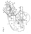
- FIG. 1 The drawings show a steering structure of a vehicle.
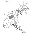
- a front body structure of the vehicle will be briefly explained with reference to Figs. 1 and 2.
- a battery 10 is mounted on an upper portion of a tire house 9, and an engine 12 is mounted on a front-side frame 11 through an engine mount.
- a numeral symbol 18 represents a front window glass
- a numeral symbol 19 represents a head lamp
- a numeral symbol 20 represents a front differential gear unit
- a numeral symbol 21 represents front wheels as steered wheel
- a numeral symbol 22 represents a servo apparatus, i.e., a so-called master back (master cylinder) for converting a stepping force of a brake pedal 23 into hydraulic pressure.
- master back master cylinder
- the steering operation unit 31 is constituted in the following manner.
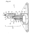
- a movable shaft 34 is provided on an outer periphery of a stationary shaft 32 through a bearing 33, and the movable shaft 34 is integrally formed with a driving bevel gear 35 at its lower end.
- a column 36 is integrally connected to an outer periphery of an upper end of the movable shaft 34.
- a horn pad 38 is mounted to an upper end of the stationary shaft 32 through a base member 37.
- An air bag inflator 39 for an air bag apparatus is disposed on an upper face of the base member 37.
- a portion of the pulley box 40 is notched to form a notch 44, a portion of the follower bevel gear 43 is brought outside from the notch 44, and this brought out portion is meshed with the driving bevel gear 35.
- Cables 45 as flexible transmitting means are wound around the driving pulley 42 in the pulley box 40, and the cables 45 are brought out from the pulley box 40 through a cable guide 46.
- the cables 45 are the transmitting means for connecting the driving pulley 42 in the pulley box 40 and the follower pulley in the pulley box 28 on the side of the steering unit 26.
- Each the cable 45 includes an outer tube and an inner cable.
- a numeral symbol 47 represents a combination switch, and a numeral symbol 48 represents a steering lock.
- a steering bracket 51 having a gate-like cross section is provided between a rear face of the dash upper panel 3 and a steering supporting member 50 (supporting portion on the vehicle side) as a reinforcing member extending in the widthwise direction of the vehicle.
- the steering supporting member 50 is provided with a fixing bracket 52 which can turn around the steering supporting member 50.
- the fixing bracket 52 comprises two member located on left and right opposite outsides of the steering bracket 51, and a connecting plate 53 (see Fig. 2) integrally connecting the two members.
- the fixing bracket 52 is provided at its front end with a pin 55 (guide means) which is inserted into an arc-shaped guide groove 54 (guide means) formed on the steering bracket 51.
- a slant rear end of the fixing bracket 52 is provided with a bent rail-mounting portion 52a.
- a slide rail 56 is mounted to the rail-mounting portion 52a.
- the slide rail 56 comprises a plurality of stationary rails (so-called outer rails) 57, 58 fixed to the rail-mounting portion 52a, a movable rail (so-called inner rail) 59 which can slide along the stationary rails 57, 58, and balls 60 ad rollers 61 interposed between these rails.
- the pulley box 40 is fixed between the bilaterally symmetrically formed movable rails 59 and 59 as shown in Figs. 5 and 6.
- the stationary rail 58 is provided with a supporting shaft 63 through a projecting piece 62, and a lock lever 64 is mounted to the supporting shaft 63.
- the lock lever 64 is biased by a spring so that the lock lever 64 is always in engagement with locking holes 58a and 59a of the rails 58 and 59.
- the steering operation unit 31 can be vertically adjusted (tiltable) around a steering supporting member 50, and is supported such that the steering operation unit 31 can be adjusted in the longitudinal direction (capable of moving telescopically) by the slide rail 56.
- a numeral symbol 65 represents a footrest (so-called ottoman) which is formed such that it can move up and down around a supporting shaft 66.
- the foot rest 65 is usually biased by a spring into an accommodated state as illustrated in the drawing, and when a crew member takes a rest and he or she desires to put his or her foot on the foot rest 65, it is turned in the clockwise direction shown in the drawing against the biasing force.
- the engine 12 is mounted on the front-side frame 11 through an engine mount rubber and an engine mount bracket 67.
- An alternator 68 (generator) is mounted on a side portion of the engine 12.
- the engine mount bracket 67 (rigidity member) and the alternator 68 are placed separately in the longitudinal direction of the vehicle and opposed to each other. Portions of the cables 45 are disposed such as to pass between both the members 67 and 68.
- the alternator 68 is set as the cutting means, and when the vehicle collides and a load equal to or greater than a predetermined value is input from outside, the alternator 68 is retreated together with the engine 12 as shown in Fig. 7, and a portion of each the cable 45 itself, i.e., a portion 45c of the cable 45 which is to be cut and separated (refer to as "a to-be separated portion 45c", hereinafter) of the cable 45 is cut and separated between the alternator 68 and the engine mount bracket 67.
- the engine 12 and the alternator 68 are retreated from a normal position a in Fig. 7 as shown in a phantom line b in Fig. 7.
- the to-be separated portion 45c (see Fig. 1) of the cable passing between the alternator 68 and the engine mount bracket 67 is cut and separated by a rear sharp portion of the alternator 68 and the engine mount bracket 67 as a rigidity member as shown in Fig. 7.
- the operational force of the steering wheel 29 by a crew member is transmitted to the steered wheels (see front wheels 21) through the operation detecting unit 30 and the transmitting means (see cable 45) and the steering unit 26, and the steered wheels (see front wheels 21) are steered.
- the load equal to or greater than the predetermined value is applied to the transmitting means (see cable 45) from outside, the transmitting means (see cable 45) is cut and separated from the portion (see to-be separated portion 45c) provided on the part of the transmitting means (see cable 45).
- the cutting means (see alternator 68) provided in the predetermined portion (see side of the engine 12) of the vehicle in correspondence with the transmitting means (see cable 45) is retreated by the load (collision load) from outside to cut and separate the transmitting means (see cable 45).
- a member which retreats and a member which does not retreat at the time of collision may be respectively provided with a cutting blade and a receiving blade, and the cable 45 may be disposed such as to pass between the cutting blade and the receiving blade which are disposed at a distance from each other.
- portions of the inner cable and outer tube may be connected to each other by a coupling, and the coupling may be cut and separated utilizing a force pulling the cable 45 by a load which is input at the time of collision, thereby separating the cable 45.
- outer peripheries of two cable guide cylinders 40a and 40a which are projected forward from the pulley box 40 are integrally formed with a plurality of projections and recesses 72 which are extended in an axial direction of the cylinder.
- the outer tubes 45b and 45b are mounted to the projections and recesses 72 such that they are disconnected when a load equal to or greater than a predetermined value is applied, thereby constituting connected portions 73 and 73.
- the connected portions 73 and 76 between the transmitting means (see cable 45) and the operation detecting unit 30 are disconnected by the relative displacement of both the elements 30 and 45 equal to or greater than the predetermined value.
- the connected portions 79 are designed such that they are disconnected when a load equal to or greater than the predetermined value is applied to the divided front inner cables 45a and 45a.
- the connected portions 78 and 79 between the transmitting means (see cable 45) and the steering unit 26 are disconnected by the relative displacement of both the elements 26 and 45 equal to or greater than the predetermined value.
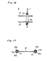
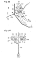
- Figs. 13 and 14 show another embodiment of the steering structure of a vehicle.
- the pair of cables 45 and 45 are connected from front of the steering unit 26, and the connected portions 78 and 79 between the steering unit 26 and the pair of cables 45 and 45 are disconnected by a retreating movement of the steering unit 26 caused by a load from outside.
Landscapes
- Engineering & Computer Science (AREA)
- Chemical & Material Sciences (AREA)
- Combustion & Propulsion (AREA)
- Transportation (AREA)
- Mechanical Engineering (AREA)
- Steering Controls (AREA)
- Power Steering Mechanism (AREA)
Claims (8)
- Lenkstruktur eines Fahrzeugs, mit
einer in einer Kabine vorgesehenen Betätigungserfassungseinheit (30) zum Erfassen der Betätigung eines Lenkrads (29) durch ein Crewmitglied,
einer in einem Motorraum (8) vorgesehenen Lenkeinheit (26) zum Lenken gelenkter Räder (21), und
biegsamen Übertragungsmitteln (45) zum Verbinden der Betätigungserfassungseinheit (30) und der Lenkeinheit (26),
dadurch gekennzeichnet, dass
das Übertragungsmittel (45) mit einem Abschnitt (45c) versehen ist, der getrennt wird, wenn eine Kraft gleich oder größer als ein vorbestimmter Wert von außen auf das Übertragungsmittel (45) aufgebracht wird. - Lenkstruktur eines Fahrzeugs nach Anspruch 1, wobei ein dem Übertragungsmittel (45) entsprechender vorbestimmter Abschnitt des Fahrzeugs mit einem Schneidmittel (68) versehen ist, das durch eine Kraft von außen zurückgezogen wird, um das Übertragungsmittel (45) zu durchschneiden.
- Lenkstruktur eines Fahrzeugs, mit
einer in einer Kabine vorgesehenen Betätigungserfassungseinheit (30) zum Erfassen der Betätigung eines Lenkrads (29) durch ein Crewmitglied,
einer in einem Motorraum (8) vorgesehenen Lenkeinheit (26) zum Lenken gelenkter Räder (21), und
biegsamen Übertragungsmitteln (45) zum Verbinden der Betätigungserfassungseinheit (30) und der Lenkeinheit (26),
wobei
ein Auflageteil (70) vorgesehen ist, um das Übertragungsmittel (45) in einem vorbestimmten Abschnitt einer Karosserie des Fahrzeugs zu tragen, dadurch gekennzeichnet, dass
das Auflageteil (70) die Auflage des Übertragungsmittels (45) von der Karosserie des Fahrzeugs löst, wenn eine relative Verschiebung zwischen dem Auflageteil (70) und dem Übertragungsmittel (45) einen vorbestimmten Betrag übersteigt. - Lenkstruktur eines Fahrzeugs nach einem der Ansprüche 1 bis 3, wobei ein Verbindungsabschnitt (73, 76) zwischen dem Übertragungsmittel (45) und der Betätigungserfassungseinheit (30) voneinander ausgerückt wird, wenn das Übertragungsmittel (45) und die Betätigungserfassungseinheit (30) mit einer relativen Verschiebung gleich oder größer als ein vorbestimmter Wert zueinander bewegt werden.
- Lenkstruktur eines Fahrzeugs nach einem der Ansprüche 1 bis 4, wobei ein Verbindungsabschnitt (78, 79) zwischen dem Übertragungsmittel (45) und der Lenkeinheit (26) voneinander ausgerückt wird, wenn das Übertragungsmittel (45) und die Lenkeinheit (26) mit einer relativen Verschiebung gleich oder größer als ein vorbestimmter Wert zueinander bewegt werden.
- Lenkstruktur eines Fahrzeugs nach Anspruch 5, wobei das Übertragungsmittel (45) von der Vorderseite der Lenkeinheit (26) aus mit dieser verbunden ist, und wobei die Lenkeinheit (26) und das Übertragungsmittel (45) voneinander getrennt werden, wenn die Lenkeinheit (26) durch eine von außen aufgebrachte Kraft zurückgezogen wird.
- Lenkstruktur eines Fahrzeugs, mit:einer in einer Kabine vorgesehenen Betätigungserfassungseinheit (30) zum Erfassen der Betätigung eines Lenkrads (29) durch ein Crewmitglied,einer in einem Motorraum (8) vorgesehenen Lenkeinheit (26) zum Lenken gelenkter Räder (21), undbiegsamen Übertragungsmitteln (45) zum Verbinden der Betätigungserfassungseinheit (30) und der Lenkeinheit (26),dadurch gekennzeichnet, dass
das Übertragungsmittel (45) mit einer vorbestimmten Biegung angeordnet ist. - Lenkstruktur eines Fahrzeugs nach Anspruch 7, wobei das Übertragungsmittel zwei Seile (45) umfasst und die zwei Seile (45) auf demselben Teil (12) gelagert sind.
Applications Claiming Priority (2)
| Application Number | Priority Date | Filing Date | Title |
|---|---|---|---|
| JP24256699A JP4433522B2 (ja) | 1999-08-30 | 1999-08-30 | 車両のステアリング構造 |
| JP24256699 | 1999-08-30 |
Publications (3)
| Publication Number | Publication Date |
|---|---|
| EP1081014A2 EP1081014A2 (de) | 2001-03-07 |
| EP1081014A3 EP1081014A3 (de) | 2005-01-05 |
| EP1081014B1 true EP1081014B1 (de) | 2007-10-17 |
Family
ID=17090993
Family Applications (1)
| Application Number | Title | Priority Date | Filing Date |
|---|---|---|---|
| EP00118303A Expired - Lifetime EP1081014B1 (de) | 1999-08-30 | 2000-08-23 | Fahrzeuglenkstruktur |
Country Status (4)
| Country | Link |
|---|---|
| US (1) | US6361074B1 (de) |
| EP (1) | EP1081014B1 (de) |
| JP (1) | JP4433522B2 (de) |
| DE (1) | DE60036764T2 (de) |
Families Citing this family (12)
| Publication number | Priority date | Publication date | Assignee | Title |
|---|---|---|---|---|
| KR100401836B1 (ko) * | 2000-12-22 | 2003-10-17 | 현대자동차주식회사 | 차량의 가속페달장치 |
| JP2003026000A (ja) * | 2001-07-12 | 2003-01-29 | Nippon Cable Syst Inc | ケーブル式のステアリング伝導装置 |
| CN100453381C (zh) * | 2004-10-27 | 2009-01-21 | 日产自动车株式会社 | 车辆前部结构 |
| JP4779471B2 (ja) | 2004-10-27 | 2011-09-28 | 日産自動車株式会社 | 車両の前部構造 |
| JP4645230B2 (ja) * | 2005-02-28 | 2011-03-09 | 日産自動車株式会社 | 車両のステアリング装置 |
| JP4506537B2 (ja) * | 2005-03-31 | 2010-07-21 | 日産自動車株式会社 | ステアリング装置 |
| DE102006001821A1 (de) * | 2006-01-13 | 2007-07-19 | Bayerische Motoren Werke Ag | Lenksystem eines zweispurigen Kraftfahrzeugs |
| JP4893239B2 (ja) * | 2006-03-07 | 2012-03-07 | 日産自動車株式会社 | 車両の前部構造 |
| IN2015DN03725A (de) * | 2012-10-17 | 2015-09-18 | Watson Diane Lee | |
| US10442458B2 (en) | 2015-01-29 | 2019-10-15 | Bombardier Recreational Products Inc. | Rack and pinion steering system |
| CN109803872B (zh) * | 2016-08-15 | 2022-06-28 | 庞巴迪动力产品公司 | 齿条齿轮式转向系统 |
| JP7338245B2 (ja) * | 2019-06-05 | 2023-09-05 | 三菱自動車工業株式会社 | 車両の構造 |
Family Cites Families (14)
| Publication number | Priority date | Publication date | Assignee | Title |
|---|---|---|---|---|
| DE3627558C1 (de) * | 1986-08-14 | 1987-12-17 | Audi Ag | Sicherheitssystem fuer Kraftfahrzeuge |
| US5052715A (en) * | 1990-03-19 | 1991-10-01 | Ford Motor Company | Passive impact restraining vehicular steering column assembly |
| JP2770563B2 (ja) * | 1990-09-18 | 1998-07-02 | 日産自動車株式会社 | 車両乗員保護装置 |
| DE4133960C2 (de) * | 1991-10-14 | 1996-08-01 | Reiche & Co | Sicherheitsvorrichtung für Kraftfahrzeug-Lenksäulen |
| JPH06286623A (ja) * | 1992-07-14 | 1994-10-11 | Morimoto Haruyo | 自動車安全ハンドル |
| DE4335511A1 (de) * | 1992-10-29 | 1994-05-05 | Volkswagen Ag | Sicherheitsvorrichtung für den Fahrer eines Fahrzeugs mit Lenkung und Pedal |
| US5535842A (en) * | 1993-03-05 | 1996-07-16 | Volkswagen Ag | Safety arrangement for collision-related disconnection of an electrical energy source from a motor vehicle supply circuit |
| JPH07144644A (ja) * | 1993-11-24 | 1995-06-06 | Toyota Motor Corp | 操舵装置 |
| JP3784492B2 (ja) * | 1997-04-23 | 2006-06-14 | 本田技研工業株式会社 | ケーブル式ステアリング装置 |
| JP3802649B2 (ja) * | 1997-05-12 | 2006-07-26 | 本田技研工業株式会社 | ケーブル式ステアリング装置 |
| JP3865008B2 (ja) | 1997-06-16 | 2007-01-10 | 中央発條株式会社 | 自動車用パワーステアリング装置 |
| JP3793323B2 (ja) | 1997-06-19 | 2006-07-05 | 本田技研工業株式会社 | ケーブル式ステアリング装置 |
| SE510856C2 (sv) * | 1997-06-23 | 1999-06-28 | Volvo Ab | Kraftupptagande anordning för skydd av åkande i fordon |
| JP3342349B2 (ja) | 1997-06-25 | 2002-11-05 | 本田技研工業株式会社 | ケーブル式ステアリング装置 |
-
1999
- 1999-08-30 JP JP24256699A patent/JP4433522B2/ja not_active Expired - Fee Related
-
2000
- 2000-08-23 EP EP00118303A patent/EP1081014B1/de not_active Expired - Lifetime
- 2000-08-23 DE DE60036764T patent/DE60036764T2/de not_active Expired - Lifetime
- 2000-08-23 US US09/643,947 patent/US6361074B1/en not_active Expired - Lifetime
Also Published As
| Publication number | Publication date |
|---|---|
| US6361074B1 (en) | 2002-03-26 |
| DE60036764T2 (de) | 2008-02-07 |
| DE60036764D1 (de) | 2007-11-29 |
| EP1081014A2 (de) | 2001-03-07 |
| JP4433522B2 (ja) | 2010-03-17 |
| EP1081014A3 (de) | 2005-01-05 |
| JP2001063587A (ja) | 2001-03-13 |
Similar Documents
| Publication | Publication Date | Title |
|---|---|---|
| EP1081014B1 (de) | Fahrzeuglenkstruktur | |
| US6345842B1 (en) | Shock absorbing type steering apparatus and a structure for mounting to an automobile body the steering apparatus | |
| US11370474B2 (en) | Steering column including a rotational blocking device actuated by a motorization | |
| US6149196A (en) | Protection device for the driver of a vehicle | |
| US5482320A (en) | Steering column assembly axially retractable in the event of impact, in particular for an automobile vehicle | |
| CA1319725C (en) | Vehicle collision safety system | |
| GB1565505A (en) | Adjustable pedal assembly for a vehicle | |
| US8540281B2 (en) | Steering system | |
| SE406303B (sv) | Arrangemang vid styrinrettningar i motorfordon | |
| JPH01254470A (ja) | ステアリング支持装置 | |
| GB2241050A (en) | Vehicle foot pedal mounting | |
| KR200142733Y1 (ko) | 자동차의 스티어링 칼럼 | |
| JP4210812B2 (ja) | 車両のステアリング装置 | |
| JP2703310B2 (ja) | 自動車のコラムカバー構造 | |
| JP2677651B2 (ja) | 自動車のニープロテクター構造 | |
| JP4715224B2 (ja) | ステアリングの支持構造 | |
| JP4448559B2 (ja) | 車両のステアリング構造 | |
| JP4221821B2 (ja) | 車両のステアリング構造 | |
| JP4221832B2 (ja) | 車両のステアリング構造 | |
| KR100326388B1 (ko) | 자동차의 브레이크 페달 지지구조 | |
| SE512800C2 (sv) | Arrangemang vid instrumentbräda hos fordon | |
| KR100514880B1 (ko) | 조향 컬럼 수축 장치 | |
| KR970007370B1 (ko) | 자동차의 조향컬럼 샤프트 | |
| JPH0360686B2 (de) | ||
| JPH06263039A (ja) | 引き込み式ステアリングコラム |
Legal Events
| Date | Code | Title | Description |
|---|---|---|---|
| PUAI | Public reference made under article 153(3) epc to a published international application that has entered the european phase |
Free format text: ORIGINAL CODE: 0009012 |
|
| AK | Designated contracting states |
Kind code of ref document: A2 Designated state(s): AT BE CH CY DE DK ES FI FR GB GR IE IT LI LU MC NL PT SE |
|
| AX | Request for extension of the european patent |
Free format text: AL;LT;LV;MK;RO;SI |
|
| PUAL | Search report despatched |
Free format text: ORIGINAL CODE: 0009013 |
|
| AK | Designated contracting states |
Kind code of ref document: A3 Designated state(s): AT BE CH CY DE DK ES FI FR GB GR IE IT LI LU MC NL PT SE |
|
| AX | Request for extension of the european patent |
Extension state: AL LT LV MK RO SI |
|
| 17P | Request for examination filed |
Effective date: 20050520 |
|
| AKX | Designation fees paid |
Designated state(s): DE |
|
| GRAP | Despatch of communication of intention to grant a patent |
Free format text: ORIGINAL CODE: EPIDOSNIGR1 |
|
| GRAS | Grant fee paid |
Free format text: ORIGINAL CODE: EPIDOSNIGR3 |
|
| GRAA | (expected) grant |
Free format text: ORIGINAL CODE: 0009210 |
|
| AK | Designated contracting states |
Kind code of ref document: B1 Designated state(s): DE |
|
| REF | Corresponds to: |
Ref document number: 60036764 Country of ref document: DE Date of ref document: 20071129 Kind code of ref document: P |
|
| PLBE | No opposition filed within time limit |
Free format text: ORIGINAL CODE: 0009261 |
|
| STAA | Information on the status of an ep patent application or granted ep patent |
Free format text: STATUS: NO OPPOSITION FILED WITHIN TIME LIMIT |
|
| 26N | No opposition filed |
Effective date: 20080718 |
|
| PGFP | Annual fee paid to national office [announced via postgrant information from national office to epo] |
Ref country code: DE Payment date: 20160816 Year of fee payment: 17 |
|
| REG | Reference to a national code |
Ref country code: DE Ref legal event code: R119 Ref document number: 60036764 Country of ref document: DE |
|
| PG25 | Lapsed in a contracting state [announced via postgrant information from national office to epo] |
Ref country code: DE Free format text: LAPSE BECAUSE OF NON-PAYMENT OF DUE FEES Effective date: 20180301 |