EP1080958A2 - Vorrichtung zum Belüften des Innenraumes eines Kraftfahrzeuges - Google Patents
Vorrichtung zum Belüften des Innenraumes eines Kraftfahrzeuges Download PDFInfo
- Publication number
- EP1080958A2 EP1080958A2 EP00117239A EP00117239A EP1080958A2 EP 1080958 A2 EP1080958 A2 EP 1080958A2 EP 00117239 A EP00117239 A EP 00117239A EP 00117239 A EP00117239 A EP 00117239A EP 1080958 A2 EP1080958 A2 EP 1080958A2
- Authority
- EP
- European Patent Office
- Prior art keywords
- cover
- outlet opening
- edge
- air
- motor vehicle
- Prior art date
- Legal status (The legal status is an assumption and is not a legal conclusion. Google has not performed a legal analysis and makes no representation as to the accuracy of the status listed.)
- Withdrawn
Links
Images

Classifications
-
- B—PERFORMING OPERATIONS; TRANSPORTING
- B60—VEHICLES IN GENERAL
- B60H—ARRANGEMENTS OF HEATING, COOLING, VENTILATING OR OTHER AIR-TREATING DEVICES SPECIALLY ADAPTED FOR PASSENGER OR GOODS SPACES OF VEHICLES
- B60H1/00—Heating, cooling or ventilating devices
- B60H1/34—Nozzles; Air-diffusers
- B60H1/3407—Nozzles; Air-diffusers providing an air stream in a fixed direction, e.g. using a grid or porous panel
-
- B—PERFORMING OPERATIONS; TRANSPORTING
- B60—VEHICLES IN GENERAL
- B60K—ARRANGEMENT OR MOUNTING OF PROPULSION UNITS OR OF TRANSMISSIONS IN VEHICLES; ARRANGEMENT OR MOUNTING OF PLURAL DIVERSE PRIME-MOVERS IN VEHICLES; AUXILIARY DRIVES FOR VEHICLES; INSTRUMENTATION OR DASHBOARDS FOR VEHICLES; ARRANGEMENTS IN CONNECTION WITH COOLING, AIR INTAKE, GAS EXHAUST OR FUEL SUPPLY OF PROPULSION UNITS IN VEHICLES
- B60K37/00—Dashboards
-
- B—PERFORMING OPERATIONS; TRANSPORTING
- B60—VEHICLES IN GENERAL
- B60H—ARRANGEMENTS OF HEATING, COOLING, VENTILATING OR OTHER AIR-TREATING DEVICES SPECIALLY ADAPTED FOR PASSENGER OR GOODS SPACES OF VEHICLES
- B60H1/00—Heating, cooling or ventilating devices
- B60H1/24—Ventilating devices where the heating or cooling is irrelevant
- B60H1/247—Disposition of several air-diffusers in a vehicle for ventilation-air circulation in a vehicle cabin
-
- B—PERFORMING OPERATIONS; TRANSPORTING
- B60—VEHICLES IN GENERAL
- B60K—ARRANGEMENT OR MOUNTING OF PROPULSION UNITS OR OF TRANSMISSIONS IN VEHICLES; ARRANGEMENT OR MOUNTING OF PLURAL DIVERSE PRIME-MOVERS IN VEHICLES; AUXILIARY DRIVES FOR VEHICLES; INSTRUMENTATION OR DASHBOARDS FOR VEHICLES; ARRANGEMENTS IN CONNECTION WITH COOLING, AIR INTAKE, GAS EXHAUST OR FUEL SUPPLY OF PROPULSION UNITS IN VEHICLES
- B60K35/00—Instruments specially adapted for vehicles; Arrangement of instruments in or on vehicles
- B60K35/50—Instruments characterised by their means of attachment to or integration in the vehicle
-
- B—PERFORMING OPERATIONS; TRANSPORTING
- B60—VEHICLES IN GENERAL
- B60K—ARRANGEMENT OR MOUNTING OF PROPULSION UNITS OR OF TRANSMISSIONS IN VEHICLES; ARRANGEMENT OR MOUNTING OF PLURAL DIVERSE PRIME-MOVERS IN VEHICLES; AUXILIARY DRIVES FOR VEHICLES; INSTRUMENTATION OR DASHBOARDS FOR VEHICLES; ARRANGEMENTS IN CONNECTION WITH COOLING, AIR INTAKE, GAS EXHAUST OR FUEL SUPPLY OF PROPULSION UNITS IN VEHICLES
- B60K2360/00—Indexing scheme associated with groups B60K35/00 or B60K37/00 relating to details of instruments or dashboards
- B60K2360/60—Structural details of dashboards or instruments
- B60K2360/65—Features of dashboards
- B60K2360/658—Dashboard parts used as air ducts
Definitions
- the invention relates to a device for ventilating the interior of a motor vehicle.
- Such devices are usually integrated in the dashboard, with various Refinements of the outlet openings for an air flow are known.
- flat Exit openings known that opened with the help of an adjustable louvre grille or can be closed.
- the louvre grille serves to determine the Outflow direction of the air flow.
- the last mentioned ventilation devices lead to the effect that a directed air flow is emitted into the interior of the motor vehicle becomes. This leads to uneven ventilation, especially of the front interior, in which the driver and the passenger sit.
- the ventilation device described above for the windshield leads to even ventilation, however The discharged air flow first hits the windshield and then runs along of the upper area of the interior.
- the size of the Air outlet gap between the cover and the outlet opening depending on the intensity setting of the ventilation is adjustable.
- the intensity of the supplied air flow which is set, for example, by an integrated fan can be controlled by the size of the air outlet gap ventilation set.
- the cover is designed to be substantially linearly adjustable preferably the direction of movement of the cover is substantially perpendicular to aligned with the outlet opening. So when you open the cover so lifted from the outlet opening that the entire air outlet gap in the Dimensions increased in that the cover moves linearly away from the outlet opening.
- the cover is arranged to be pivotable about an axis, preferably with the axis oriented substantially horizontally and at the top End of the cover is arranged.
- the cover unfolded so that the air outlet gap in the area of the axis is smaller than at the end of the cover, which is arranged opposite the axis.
- the air duct at least partially forms the guide mechanism mentioned above, so that both functions are realized integrally through the wall of the air duct are. This reduces the design effort for the ventilation device.
- the cover preferably has at least one operating element that is designed in particular as a rotary knob.
- this control element of the setting is used for ventilation, it can preferably also for driving an adjustment mechanism can be used to adjust the cover.
- an operating element not only the strength of the air flow, but also at the same time the size of the air outlet gap can be set.
- FIG. 1 shows a dashboard of a motor vehicle in the form of a schematic sketch, for the sake of clarity, the various indicators and actuators that are usually arranged there, have been omitted and for orientation only one steering wheel 4 is located.
- An outlet opening 6 is shown in the dashboard 2, only the right edge of the outlet opening 6 can be seen in FIG. 1.
- Through the Outlet opening 6 can be an air flow, which is determined either by the speed of travel Motor vehicle or has been generated by a fan in the interior of the Motor vehicle enter.
- There is also a cover 8 for closing and releasing the outlet opening 6 is provided.
- Fig. 1 is the open state of the ventilation device shown, in which between the edge 10 of the outlet opening 6 and the edge 12 Cover 8 an air outlet gap 14 is formed.
- the air outlet gap 14 is as black stripe shown.
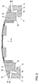
- Fig. 2 shows in cross section a first embodiment of a device according to the invention for ventilating the interior of a motor vehicle.
- the dashboard 2 is closed shown in detail on both sides of FIG. 2 and has the outlet opening 6.
- the Cover 8 has a plurality of components, but not for the function the ventilation device, but mainly the aesthetic design of the cover 8 serve.
- the cover 8 is spaced apart from the outlet opening 6 or arranged to the dashboard 2.
- the outlet opening 6 and the cover 8 of the air outlet gap 14 is formed, as from both the left and right Edge of Fig. 2 is shown. Due to the shape of the edge 10 of the outlet opening 6 and the edge 12 of the cover 8 results in a curved or angular course of the air outlet gap 14.
- the edge 10 Since the profiles of the edge 10 and the edge 12 are complementary to each other are in the closed state, the edge 10 is essentially completely on the edge 12 on, as can be easily seen from Fig. 2, when the cover 8 along the arrow A in Direction of the outlet opening 6 is adjusted.
- the edge 10 and the edge 12 are at least partially each designed as a contact surface 16 or 18.
- Fig. 1 further shows that the air outlet gap 14 is essentially complete, at least but partially the cover 8 is formed all around. This creates a wide airflow generated that evenly ventilates the front area of the interior of the motor vehicle.
- the cover is essentially linearly adjustable formed, the direction of movement of the cover 8 substantially perpendicular is aligned with the surface formed by the outlet opening 6. See in particular arrow A in FIG. 2.
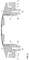
- Fig. 3 shows a further embodiment of the present device for ventilation of the Interior of the motor vehicle, the same reference numerals as the same components denote in the first embodiment.
- an air duct 20 guiding an air flow is provided here, which is defined in Way supplies the air flow to the outlet opening 6.
- the air channel 20 have a different width, whereby the Intensity of the air flow emerging from the air outlet gap 14 along the gap 14 can be adjusted to different degrees.
- the air duct 20 thus ensures that the cover 8 and the outlet opening 6 formed air outlet gap 14 in a defined manner from the supplied air flow is flowed to. Furthermore, the wall 22 of the air duct 20 is used with one with the Cover 8 connected guide element 24 to be in sliding engagement, so that a guide mechanism for the movement of the cover 8 from the wall 22 and the guide element 24 is formed. Thus, the air duct 20 and the guide mechanism 24 at least partially realized by the wall 22.
- the Operating elements 30 are designed as rotary knobs, with at least one operating element 30 serves to adjust the ventilation. It is preferred that the setting the ventilation control element 30 a not shown in the drawing Adjustment mechanism drives the adjustment of the cover between the closed and the open position. Thus both the strength of the fed Air flow and the width of the air outlet gap 14 via an operating element 30 set. Ergonomic and clear handling of the ventilation device is the consequence.
Landscapes
- Engineering & Computer Science (AREA)
- Mechanical Engineering (AREA)
- Chemical & Material Sciences (AREA)
- Combustion & Propulsion (AREA)
- Transportation (AREA)
- Physics & Mathematics (AREA)
- Thermal Sciences (AREA)
- Air-Conditioning For Vehicles (AREA)
Abstract
Description
- Fig. 1
- eine dreidimensionale schematisierende Darstellung eines Armaturenbrettes mit einer erfindungsgemäßen Vorrichtung zum Belüften des Innenraumes eines Kraftfahrzeuges,
- Fig. 2
- ein erstes Ausführungsbeispiel einer erfindungsgemäßen Vorrichtung im Querschnitt und
- Fig. 3
- ein drittes Ausführungsbeispiel einer erfindungsgemäßen Vorrichtung.
Claims (22)
- Vorrichtung zum Belüften des Innenraumes eines Kraftfahrzeuges, wobei das Kraftfahrzeug ein Armaturenbrett (2) aufweist,mit einer im Armaturenbrett (2) angeordneten Austrittsöffnung (6) für einen Luftstrom undmit einer Abdeckung (8) zum Verschließen und Freigeben der Austrittsöffnung (6),wobei im geöffneten Zustand zwischen dem Rand (10) der Austrittsöffnung (6) und dem Rand (12) der Abdeckung (8) ein Luftaustrittsspalt (14) ausgebildet ist.
- Vorrichtung nach Anspruch 1,
dadurch gekennzeichnet, daß
im verschlossenen Zustand der Rand (10) der Austrittsöffnung (6) und der Rand (12) der Abdeckung (8) im wesentlichen vollständig aneinander an liegen. - Vorrichtung nach Anspruch 1 oder 2,
dadurch gekennzeichnet, daß
die Form des Randes (10) der Austrittsöffnung (6) im wesentlichen mit der Form des Randes (12) der Abdeckung (8) übereinstimmt. - Vorrichtung nach Anspruch 3,
dadurch gekennzeichnet, daß
der Rand (10) der Austrittsöffnung (6) zumindest teilweise als Anlagefläche (16) ausgebildet ist. - Vorrichtung nach Anspruch 3 oder 4,
dadurch gekennzeichnet, daß
der Rand (12) der Abdeckung (8) zumindest teilweise als Anlagefläche (18) ausgebildet ist. - Vorrichtung nach einem der Ansprüche 1 bis 5,
dadurch gekennzeichnet, daß
der Luftaustrittsspalt (14) zumindest teilweise umlaufend ausgebildet ist. - Vorrichtung nach einem der Ansprüche 1 bis 6,
dadurch gekennzeichnet, daß
die Größe des Luftaustrittsspaltes (14) zwischen der Abdeckung (8) und der Austrittsöffnung (6) in Abhängigkeit von der Intensitätseinstellung der Lüftung verstellbar ist. - Vorrichtung nach einem der Ansprüche 1 bis 7,
dadurch gekennzeichnet, daß
die Abdeckung (8) im wesentlichen linear verstellbar ist. - Vorrichtung nach Anspruch 8,
dadurch gekennzeichnet, daß
die Bewegungsrichtung der Abdeckung (8) im wesentlichen senkrecht zur von der Austrittsöffnung (6) gebildeten Fläche ausgerichtet ist. - Vorrichtung nach einem der Ansprüche 1 bis 7,
dadurch gekennzeichnet, daß
die Abdeckung (8) um eine Achse verschwenkbar angeordnet ist. - Vorrichtung nach Anspruch 10,
dadurch gekennzeichnet, daß
die Achse im wesentlichen horizontal ausgerichtet ist. - Vorrichtung nach Anspruch 10 oder 11,
dadurch gekennzeichnet, daß
die Achse am oberen Ende der Abdeckung (8) angeordnet ist. - Vorrichtung nach einem der Ansprüche 1 bis 12,
dadurch gekennzeichnet, daß
eine Führungsmechanik (24) zur Führung der Verstellbewegung der Abdeckung (8) vorgesehen ist. - Vorrichtung nach einem der Ansprüche 1 bis 13,
dadurch gekennzeichnet, daß
die Austrittsöffnung (6) mit einem einen Luftstrom führenden Luftkanal (20) verbunden ist. - Vorrichtung nach Anspruch 14,
dadurch gekennzeichnet, daß
der Luftkanal (20) zumindest teilweise die Führungsmechanik (24) bildet. - Vorrichtung nach einem der Ansprüche 1 bis 15,
dadurch gekennzeichnet, daß
das Armaturenbrett (2) eine Mittelkonsole (26) aufweist und daß die Austrittsöffnung (6) in der Mittelkonsole (26) angeordnet ist. - Vorrichtung nach Anspruch 16,
dadurch gekennzeichnet, daß
die Längsausdehnung der Austrittsöffnung (6) größer als die halbe Höhe, insbesondere größer als zwei Drittel der Höhe, vorzugsweise größer als drei Viertel der Höhe des im wesentlichen nach oben ausgerichteten Abschnittes (28) der Mittelkonsole (26) ist. - Vorrichtung nach Anspruch 16 oder 17,
dadurch gekennzeichnet, daß
die Breite der Austrittsöffnung (6) größer als die halbe Breite, insbesondere größer als zwei Drittel der Breite, vorzugsweise größer als drei Viertel der Breite des im wesentlichen nach oben ausgerichteten Abschnittes (28) der Mittelkonsole (26) ist. - Vorrichtung nach einem der Ansprüche 1 bis 18,
dadurch gekennzeichnet, daß
die Abdeckung (8) mindestens ein Bedienungselement (30) aufweist. - Vorrichtung nach Anspruch 19,
dadurch gekennzeichnet, daß
das Bedienungselement (30) als Drehknopf ausgebildet ist. - Vorrichtung nach Anspruch 19 oder 20,
dadurch gekennzeichnet, daß
das Bedienungselement (30) der Einstellung der Lüftung dient. - Vorrichtung nach einem der Ansprüche 19 bis 21,
dadurch gekennzeichnet, daß
eine Verstellmechanik zum Verstellen der Abdeckung (8) vorgesehen ist und daß das Bedienungselement (30) die Verstellmechanik betätigt.
Applications Claiming Priority (2)
| Application Number | Priority Date | Filing Date | Title |
|---|---|---|---|
| DE19941618 | 1999-09-01 | ||
| DE19941618A DE19941618B4 (de) | 1999-09-01 | 1999-09-01 | Vorrichtung zum Belüften des Innenraumes eines Kraftfahrzeuges |
Publications (2)
| Publication Number | Publication Date |
|---|---|
| EP1080958A2 true EP1080958A2 (de) | 2001-03-07 |
| EP1080958A3 EP1080958A3 (de) | 2002-09-18 |
Family
ID=7920406
Family Applications (1)
| Application Number | Title | Priority Date | Filing Date |
|---|---|---|---|
| EP00117239A Withdrawn EP1080958A3 (de) | 1999-09-01 | 2000-08-14 | Vorrichtung zum Belüften des Innenraumes eines Kraftfahrzeuges |
Country Status (2)
| Country | Link |
|---|---|
| EP (1) | EP1080958A3 (de) |
| DE (1) | DE19941618B4 (de) |
Cited By (3)
| Publication number | Priority date | Publication date | Assignee | Title |
|---|---|---|---|---|
| FR2837155A1 (fr) * | 2002-03-13 | 2003-09-19 | Foggini France | Bandeau de decoration pour habitacle de vehicules susceptible d'assurer une diffusion douce d'air |
| EP1288033A3 (de) * | 2001-08-24 | 2003-11-05 | Siemens Aktiengesellschaft | Kraftfahrzeug mit Luftauslassöffnungen |
| EP3708394A1 (de) * | 2019-03-13 | 2020-09-16 | Audi Ag | Lüftungsöffnungsvorrichtung für ein klimatisierungssystem eines fahrzeugs |
Families Citing this family (6)
| Publication number | Priority date | Publication date | Assignee | Title |
|---|---|---|---|---|
| DE102004014899B4 (de) * | 2003-09-09 | 2013-08-14 | Volkswagen Ag | Ausströmer mit Bedienelement in der Mitte |
| DE10355247A1 (de) * | 2003-11-26 | 2005-06-30 | Volkswagen Ag | Vorrichtung zur Luftmengenregulierung |
| DE102005054292A1 (de) * | 2005-11-11 | 2007-05-16 | Behr Gmbh & Co Kg | Luftausströmer |
| DE102009011710A1 (de) * | 2009-03-09 | 2010-09-16 | Volkswagen Ag | Anordnung zur Luftverteilung im Innenraum eines Kraftfahrzeuges |
| DE102015001477A1 (de) | 2015-02-06 | 2015-12-03 | Audi Ag | Ausströmer für eine Belüftungsvorrichtung eines Kraftfahrzeugs und zugehörige Belüftungsvorrichtung |
| DE102025117059A1 (de) * | 2025-05-05 | 2026-03-26 | Audi Aktiengesellschaft | Fahrzeugkomponente, Fahrzeugkomponentenbaugruppe und Kraftfahrzeug |
Family Cites Families (8)
| Publication number | Priority date | Publication date | Assignee | Title |
|---|---|---|---|---|
| DE473951C (de) * | 1927-08-26 | 1929-03-25 | Max Schlawe | Heissluftverteiler fuer Frischluftheizungen in Kraftfahrzeugen |
| DE7532638U (de) * | 1975-10-14 | 1976-02-19 | Gebr. Happich Gmbh, 5600 Wuppertal | Luefter, insbesondere fuer fahrzeuge |
| FR2541958B1 (fr) * | 1983-02-25 | 1990-11-16 | Honda Motor Co Ltd | Tableau de bord perfectionne pour vehicules |
| DE3509537A1 (de) * | 1985-03-16 | 1986-09-25 | Bayerische Motoren Werke AG, 8000 München | Belueftungseinrichtung |
| US5162018A (en) * | 1991-11-18 | 1992-11-10 | Horton Donald L | Air vent system |
| DE4403096A1 (de) * | 1994-02-02 | 1995-08-03 | Happich Gmbh Gebr | Belüftungseinheit |
| US5752877A (en) * | 1996-02-28 | 1998-05-19 | Collins & Aikman Plastics, Inc. | Popup A/C outlet |
| DE19733469C1 (de) * | 1997-08-02 | 1998-08-06 | Mc Micro Compact Car Ag | Belüftungseinrichtung für ein Kraftfahrzeug |
-
1999
- 1999-09-01 DE DE19941618A patent/DE19941618B4/de not_active Expired - Fee Related
-
2000
- 2000-08-14 EP EP00117239A patent/EP1080958A3/de not_active Withdrawn
Cited By (5)
| Publication number | Priority date | Publication date | Assignee | Title |
|---|---|---|---|---|
| EP1288033A3 (de) * | 2001-08-24 | 2003-11-05 | Siemens Aktiengesellschaft | Kraftfahrzeug mit Luftauslassöffnungen |
| FR2837155A1 (fr) * | 2002-03-13 | 2003-09-19 | Foggini France | Bandeau de decoration pour habitacle de vehicules susceptible d'assurer une diffusion douce d'air |
| EP1350648A3 (de) * | 2002-03-13 | 2003-10-22 | Foggini France | Dekorative Blende für einen Fahrzeuginnenraum zur sanften Luftverteilung |
| EP3708394A1 (de) * | 2019-03-13 | 2020-09-16 | Audi Ag | Lüftungsöffnungsvorrichtung für ein klimatisierungssystem eines fahrzeugs |
| WO2020182431A1 (en) * | 2019-03-13 | 2020-09-17 | Audi Ag | Ventilation opening device for an air conditioning system of a vehicle |
Also Published As
| Publication number | Publication date |
|---|---|
| DE19941618B4 (de) | 2010-09-02 |
| EP1080958A3 (de) | 2002-09-18 |
| DE19941618A1 (de) | 2001-03-08 |
Similar Documents
| Publication | Publication Date | Title |
|---|---|---|
| DE2813909C2 (de) | Instrumententafel für Kraftfahrzeuge | |
| DE102008050180B4 (de) | Luftauslassdüse | |
| DE2153743C3 (de) | Luftdüse für eine Belüftungsanlage | |
| DE102017120417A1 (de) | Luftausströmer mit einstellbarer Luftaustrittsrichtung, insbesondere Flach- oder Fugenausströmer | |
| DE4446708C2 (de) | Lüftungsöffnung für die Zuführung von klimatisierter Luft | |
| DE102018122999A1 (de) | Luftausströmer | |
| EP1270286B1 (de) | Luftleitvorrichtung, insbesondere eines Fahrzeugs | |
| DE102018110093A1 (de) | Luftausströmer | |
| DE102024003513A1 (de) | Belüftungseinrichtung für einen Kraftwagen sowie Verfahren | |
| DE19941618B4 (de) | Vorrichtung zum Belüften des Innenraumes eines Kraftfahrzeuges | |
| DE102021111535A1 (de) | Luftausströmeranordnung | |
| EP0988165B1 (de) | Luftstromregulierungsdüse zur belüftung eines kraftfahrzeuginnenraumes | |
| DE69208663T2 (de) | Radiallüfter | |
| DE3333878A1 (de) | Belueftungsduese | |
| DE102018129562A1 (de) | Luftausströmer für ein fahrzeug sowie belüftungssystem mit einem solchen luftausströmer | |
| DE102018004910A1 (de) | Luftausströmer für einen Kraftwagen, insbesondere für einen Personenkraftwagen | |
| DE202004016983U1 (de) | Luftdüse | |
| DE10209074A1 (de) | Belüftungseinrichtung | |
| DE69406326T2 (de) | Vorhang mit Strömungsregelung | |
| DE2148281C2 (de) | Luftzufuhreinrichtung fur den Innen raum von Kraftfahrzeugen | |
| DE102022100478A1 (de) | Luftausströmer für ein fahrzeug sowie luftausströmersystem | |
| DE102021201048A1 (de) | Ausströmervorrichtung für eine Belüftungs- oder Klimatisierungsanlage eines Kraftfahrzeugs, Ausströmeranordnung | |
| DE202023100756U1 (de) | Luftausströmer mit einstellbarer Luftaustrittsrichtung | |
| DE102020110628B4 (de) | Luftausströmer für ein Kraftfahrzeug und Kraftfahrzeug | |
| DE10103551A1 (de) | Instrumententafel für ein Fahrzeug, insbesondere für ein Kraftfahrzeug |
Legal Events
| Date | Code | Title | Description |
|---|---|---|---|
| PUAI | Public reference made under article 153(3) epc to a published international application that has entered the european phase |
Free format text: ORIGINAL CODE: 0009012 |
|
| AK | Designated contracting states |
Kind code of ref document: A2 Designated state(s): AT BE CH CY DE DK ES FI FR GB GR IE IT LI LU MC NL PT SE |
|
| AX | Request for extension of the european patent |
Free format text: AL;LT;LV;MK;RO;SI |
|
| PUAL | Search report despatched |
Free format text: ORIGINAL CODE: 0009013 |
|
| AK | Designated contracting states |
Kind code of ref document: A3 Designated state(s): AT BE CH CY DE DK ES FI FR GB GR IE IT LI LU MC NL PT SE |
|
| AX | Request for extension of the european patent |
Free format text: AL;LT;LV;MK;RO;SI |
|
| RIC1 | Information provided on ipc code assigned before grant |
Free format text: 7B 60H 1/24 A, 7B 60H 1/34 B |
|
| AKX | Designation fees paid | ||
| REG | Reference to a national code |
Ref country code: DE Ref legal event code: 8566 |
|
| STAA | Information on the status of an ep patent application or granted ep patent |
Free format text: STATUS: THE APPLICATION IS DEEMED TO BE WITHDRAWN |
|
| 18D | Application deemed to be withdrawn |
Effective date: 20030304 |