EP1079098A2 - Dosiervorrichtung - Google Patents
Dosiervorrichtung Download PDFInfo
- Publication number
- EP1079098A2 EP1079098A2 EP00117809A EP00117809A EP1079098A2 EP 1079098 A2 EP1079098 A2 EP 1079098A2 EP 00117809 A EP00117809 A EP 00117809A EP 00117809 A EP00117809 A EP 00117809A EP 1079098 A2 EP1079098 A2 EP 1079098A2
- Authority
- EP
- European Patent Office
- Prior art keywords
- actuator
- hydraulic
- chamber
- valve
- valve according
- Prior art date
- Legal status (The legal status is an assumption and is not a legal conclusion. Google has not performed a legal analysis and makes no representation as to the accuracy of the status listed.)
- Granted
Links
- 239000012530 fluid Substances 0.000 claims abstract description 62
- 238000000034 method Methods 0.000 claims abstract description 9
- 239000002184 metal Substances 0.000 claims description 32
- 229910052751 metal Inorganic materials 0.000 claims description 32
- 238000007789 sealing Methods 0.000 claims description 21
- 229920002545 silicone oil Polymers 0.000 claims description 7
- 238000002347 injection Methods 0.000 description 14
- 239000007924 injection Substances 0.000 description 14
- 239000000446 fuel Substances 0.000 description 8
- 239000007788 liquid Substances 0.000 description 7
- 238000004519 manufacturing process Methods 0.000 description 6
- 230000006835 compression Effects 0.000 description 5
- 238000007906 compression Methods 0.000 description 5
- 238000013016 damping Methods 0.000 description 5
- 230000000694 effects Effects 0.000 description 4
- 239000004033 plastic Substances 0.000 description 3
- 230000036316 preload Effects 0.000 description 3
- PXHVJJICTQNCMI-UHFFFAOYSA-N Nickel Chemical group [Ni] PXHVJJICTQNCMI-UHFFFAOYSA-N 0.000 description 2
- -1 dimethylsiloxanes Chemical class 0.000 description 2
- 238000005538 encapsulation Methods 0.000 description 2
- 238000005516 engineering process Methods 0.000 description 2
- 230000002349 favourable effect Effects 0.000 description 2
- 239000012528 membrane Substances 0.000 description 2
- 239000005060 rubber Substances 0.000 description 2
- 230000035882 stress Effects 0.000 description 2
- 238000003466 welding Methods 0.000 description 2
- HSFWRNGVRCDJHI-UHFFFAOYSA-N Acetylene Chemical compound C#C HSFWRNGVRCDJHI-UHFFFAOYSA-N 0.000 description 1
- 230000001133 acceleration Effects 0.000 description 1
- 239000000654 additive Substances 0.000 description 1
- 230000000996 additive effect Effects 0.000 description 1
- 230000032683 aging Effects 0.000 description 1
- 230000005540 biological transmission Effects 0.000 description 1
- 238000012885 constant function Methods 0.000 description 1
- 230000001419 dependent effect Effects 0.000 description 1
- 238000010586 diagram Methods 0.000 description 1
- 238000006073 displacement reaction Methods 0.000 description 1
- 238000005553 drilling Methods 0.000 description 1
- 238000004070 electrodeposition Methods 0.000 description 1
- 230000007613 environmental effect Effects 0.000 description 1
- 239000007789 gas Substances 0.000 description 1
- 239000011261 inert gas Substances 0.000 description 1
- 238000012423 maintenance Methods 0.000 description 1
- 239000002480 mineral oil Substances 0.000 description 1
- 229910052759 nickel Inorganic materials 0.000 description 1
- 230000003068 static effect Effects 0.000 description 1
- 239000000725 suspension Substances 0.000 description 1
Images


Classifications
-
- F—MECHANICAL ENGINEERING; LIGHTING; HEATING; WEAPONS; BLASTING
- F02—COMBUSTION ENGINES; HOT-GAS OR COMBUSTION-PRODUCT ENGINE PLANTS
- F02M—SUPPLYING COMBUSTION ENGINES IN GENERAL WITH COMBUSTIBLE MIXTURES OR CONSTITUENTS THEREOF
- F02M51/00—Fuel-injection apparatus characterised by being operated electrically
- F02M51/06—Injectors peculiar thereto with means directly operating the valve needle
- F02M51/0603—Injectors peculiar thereto with means directly operating the valve needle using piezoelectric or magnetostrictive operating means
-
- F—MECHANICAL ENGINEERING; LIGHTING; HEATING; WEAPONS; BLASTING
- F02—COMBUSTION ENGINES; HOT-GAS OR COMBUSTION-PRODUCT ENGINE PLANTS
- F02M—SUPPLYING COMBUSTION ENGINES IN GENERAL WITH COMBUSTIBLE MIXTURES OR CONSTITUENTS THEREOF
- F02M61/00—Fuel-injectors not provided for in groups F02M39/00 - F02M57/00 or F02M67/00
- F02M61/04—Fuel-injectors not provided for in groups F02M39/00 - F02M57/00 or F02M67/00 having valves, e.g. having a plurality of valves in series
- F02M61/08—Fuel-injectors not provided for in groups F02M39/00 - F02M57/00 or F02M67/00 having valves, e.g. having a plurality of valves in series the valves opening in direction of fuel flow
-
- F—MECHANICAL ENGINEERING; LIGHTING; HEATING; WEAPONS; BLASTING
- F16—ENGINEERING ELEMENTS AND UNITS; GENERAL MEASURES FOR PRODUCING AND MAINTAINING EFFECTIVE FUNCTIONING OF MACHINES OR INSTALLATIONS; THERMAL INSULATION IN GENERAL
- F16K—VALVES; TAPS; COCKS; ACTUATING-FLOATS; DEVICES FOR VENTING OR AERATING
- F16K31/00—Actuating devices; Operating means; Releasing devices
- F16K31/004—Actuating devices; Operating means; Releasing devices actuated by piezoelectric means
- F16K31/007—Piezo-electric stacks
-
- F—MECHANICAL ENGINEERING; LIGHTING; HEATING; WEAPONS; BLASTING
- F02—COMBUSTION ENGINES; HOT-GAS OR COMBUSTION-PRODUCT ENGINE PLANTS
- F02M—SUPPLYING COMBUSTION ENGINES IN GENERAL WITH COMBUSTIBLE MIXTURES OR CONSTITUENTS THEREOF
- F02M2200/00—Details of fuel-injection apparatus, not otherwise provided for
- F02M2200/16—Sealing of fuel injection apparatus not otherwise provided for
-
- F—MECHANICAL ENGINEERING; LIGHTING; HEATING; WEAPONS; BLASTING
- F02—COMBUSTION ENGINES; HOT-GAS OR COMBUSTION-PRODUCT ENGINE PLANTS
- F02M—SUPPLYING COMBUSTION ENGINES IN GENERAL WITH COMBUSTIBLE MIXTURES OR CONSTITUENTS THEREOF
- F02M2200/00—Details of fuel-injection apparatus, not otherwise provided for
- F02M2200/26—Fuel-injection apparatus with elastically deformable elements other than coil springs
Definitions
- the invention relates to a metering device with an electromechanical Actuator that drives a valve needle.
- a piezo actuator is a valve needle drives via a hydraulic chamber.
- the piezo actuator is housed in a separate chamber and by O-rings sealed against the hydraulic fluid.
- the Piezo actuator is pre-stressed by means of a disc spring held and is supported on the housing.
- EP 0 218 895 B1 describes a metering valve for metering Liquids or gases known, in which there is a multi-layer piezo actuator within a fuel-filled bore section is located, and an end face of the piezo actuator is connected to an outwardly opening valve needle, while the other end of the piezo actuator with a damping piston is connected, which limits a damping space.
- the damping space is connected via at least one throttle gap connected to an equalization room, which is from the damping room, Throttle gap and compensation space provided volumes filled with liquid and hermetically sealed.
- One is an object of the present invention, a metering device with a hydraulic length compensation, which has a slow length compensation realized in a simple way.
- Dosing fluid can be dispensed metered, for. B. a fuel like Petrol or diesel for fuel injection.
- the dosing device a valve chamber in a housing in which one Valve needle is receivable.
- valve needle poses together with a wall of the housing represents a valve, e.g. B. an outward opening poppet valve or an injection opening opening inwards.
- the valve is due to spring forces acting directly or indirectly on the valve needle act, lockable and via an elongation of a Piezo actuator and a corresponding stroke movement of the valve needle to open.
- the piezo actuator is harmful to avoid Tension tension pre-stressed.
- the piezo actuator is located in an actuator space, one in Longitudinal direction, which corresponds to the main direction of elongation, of the piezo actuator acting hydraulic piston the piezo actuator to the side facing away from the valve needle.
- the hydraulic piston forms a hydraulic chamber together with the housing, which with the actuator space has a fit between Hydraulic piston and housing hydraulically throttled together are connected.
- the hydraulic Throttling goes without saying that it has a radial fit is controllable.
- an axially flexible sealing element which hermetically seals the actuator chamber from the valve chamber, so that no fluid exchange between the actuator space and Valve space can take place.
- Choosing an axially flexible Sealing element is not restricted and can, for. B. one Include metal, rubber or plastic bellows or a membrane.
- the compensation space does not have to be installed in the housing but can also be used as a separate, with supply lines in connection with the hydraulic chamber standing chamber.
- the actuator chamber, the hydraulic chamber and the compensation chamber are filled with a hydraulic fluid under pressure, so that the system hydraulic chamber - compensation room - Actuator space - hydraulic fluid a dynamically stiff bearing for the piezo actuator and a length compensation element for time forms longer processes.
- this includes System also hydraulic acting between rooms Links.
- This metering device has the advantage that it does not Has seals, so that it is very low maintenance.
- a permanent basic pressure can also advantageously be the hydraulic chamber are maintained, whereby a constant function independent of fuel pressure the dosing device is made possible.
- the basic pressure also has the advantage that the hydraulic chamber temporarily has high tensile and compressive forces can take up, which causes a closing of the valve very much faster (typically five to ten times faster9 can.
- the pressure from the hydraulic fluid is also advantageous conditional hydraulic pressure preload of the piezo actuator, because there is no loss in a directing of the Piezo actuator occurs.
- the piezo actuator can also be in direct contact with the hydraulic fluid advantageously be cooled.
- the hydraulic fluid is conveniently a silicone oil, which has very good dielectric and inert properties. Silicone oils are primarily polymeric dimethylsiloxanes understood. It is particularly advantageous if that Silicone oil is filled in bubble-free in the basic state.
- the pressure of the hydraulic fluid is in the range from 1 bar to 20 bar, in particular 10 bar to 20 bar. It is particularly advantageous if the pressure the hydraulic fluid through the spring properties of a Bellows, in particular a metal bellows, is provided, which for Seals the hydraulic chamber. Is even more advantageous it if an additional spring element is used to apply the pressure is available.
- valve needle is conveniently with a footplate of the Piezo actuator welded so that gap suspension is minimized and at the same time the piezo actuator from unfavorable voltage increases is protected.
- the piezo actuator is a piezoelectric one Is multilayer actuator.
- the piezo actuator by means of a Return spring is biased, e.g. B. one in the actuator space introduced spring, which is on the housing and on the Supports the footplate.
- the piezo actuator in particular in a Bourdon tube a slot tube spring is inserted and from this is biased.
- the piezo actuator is in a Bellows, in particular a metal bellows, is introduced and by this is pre-stressed.
- the Actuator exterior space relates the properties of the actuator space on filling and hydraulic connections while which the actuator interior is closed. This is it is possible to change the static and dynamic properties of the Receiving dosing device, and at the same time the piezo actuator to protect. This protection can be done, among other things happen that an atmosphere that is chemically inert to the actuator is produced in the interior of the actuator and in that now by a pressure difference between the actuator exterior and Actuator interior an additional pressure force also the piezo actuator is exercised.
- the actuator interior that contains the piezo actuator encloses, has no hydraulic fluid, but preferably an inert liquid or an inert gas, on the other hand, the actuator exterior is filled with the hydraulic fluid is.
- the actuator interior is filled with air or welding gas is filled under atmospheric pressure.
- Figure 2a shows a side view in a sectional view Housing 101, which is axially displaceable in a bore arranged hydraulic piston 103 contains.
- the hydraulic piston 103 becomes a bore of the housing 101 in a hydraulic chamber 131 and a working chamber 161 divided.
- the hydraulic piston 103 through a reference the longitudinal axis of the bore rotationally symmetrical metal bellows 25 connected to the housing 101.
- the working chamber 161 in turn becomes an actuator interior 81 and divided into an actuator outer space 82.
- the actuator outer space 82 is subjected to a pressure pA. In this exemplary embodiment there is no further feed line to the Given actuator outer space 82.
- the actuator interior 81 separated from the actuator exterior 82 are under pressure pI, where pI ⁇ pA. Thereby acts on the metal bellows 25, the pressure force Fp, which for the Case pA> pI compressed the metal bellows 25.
- the on the hydraulic piston 103 applied force Fp thus corresponds to the vector addition that on the surface of the hydraulic piston 103 acting forces.
- the hydraulic piston 103 is stepped with a larger diameter and a smaller one Executed diameter, the metal bellows 25 on the one hand the outside of the hydraulic piston 103 at the smaller diameter is attached and on the other hand with the same diameter on a circumferential nose of the housing 1.
- FIG. 2a shows an analogous case of a hydraulic piston 104, which, however, now faces away from the hydraulic chamber 103 Side is not connected to a metal bellows 25, but rests on a second inlet 22, the second inlet 22 is under pressure pI.
- the hydraulic piston 104 has a hydraulic diameter ie.
- Figure 1a shows a sectional side view of a Dosing device as an injection valve for fuel with a hydraulic length compensation element.
- the length compensation element comprises a hydraulic piston 1 a drive unit, which together with the housing 2 of the metering valve forms a hydraulic chamber 3.
- the hydraulic piston 1 has a diameter d4.
- the hydraulic chamber 3 is via a throttled connection in the form of a tight fit 21 between hydraulic piston 1 and housing 2 with a Actuator room 17 connected.
- a piezoelectric multilayer actuator is located in the actuator space 17 (PMA) 4, preferably in low voltage technology, as Part of the drive unit.
- the PMA 4 is above the hydraulic piston 1 and a base plate 5 within a metal bellows 25 with hydraulic diameter d3 hermetically sealed.
- the actuator space 17 in an actuator interior 23 which includes the PMA 4 and which is not is filled with hydraulic fluid, and an actuator exterior 24, which is filled with the hydraulic fluid, divided.
- the actuator interior 23 is preferably under atmospheric pressure filled with air.
- the welding of the metal bellows 25 is favorable for sealing of the piezo actuator 4 with respect to the hydraulic fluid and to avoid a bounce between the drive unit and a valve needle 7.
- the metal bellows 25 of the PMA 4 under a pressure preload (typically approx. 500 N).
- the base plate 5 can optionally be designed so that they together with the valve housing 2 as a guide for the valve needle 7 serves. This requires the footplate 5 to be guided inside the actuator chamber 17, the guidance of the valve needle 7 is sufficient at its outer lower end. This leadership causes the valve needle 7 to stabilize.
- valve seat 9 is incorporated into the valve body together with the one located at the lower end of the valve needle 7
- Valve plate 10 forms a poppet valve.
- the diameter of the valve seat 9, the outer diameter of the poppet valve corresponds to the sealing line d1.
- a pressure-preloaded return spring 8 holds the poppet valve with a restoring force Fr in the initial state of the metering device, where this is contracted, closed.
- the Return spring is supported on the housing 2 and on the base plate 5.
- valve needle 7 Part of the valve needle 7 is surrounded by a valve chamber 18, which is formed by the valve needle 7 and the housing 2 becomes.
- the valve chamber 18 is formed here by a bore, in which the valve needle 7 is guided far. It is by means of a fluid or fuel supply 19 can be pressurized and hydraulically connected to the poppet valve, so that with the poppet valve open, d. H. if the valve plate 10 is lifted off the valve seat 9, a fluid flow from the valve chamber 18 flows to the poppet valve and the metering fluid over the Poppet valve is released to the outside.
- the valve chamber 18 is hermetically sealed from the actuator chamber 17 by a seal which is flexible in the direction of displacement of the valve needle 7, here: a further metal bellows 26 with a hydraulic diameter d2.
- the further metal bellows 26 is connected by sealing welds at its lower end to the valve needle 7 and at its upper end to the housing 2, so that its outside is exposed to the pressure of the metering fluid supplied by the fluid or fuel supply 19 and its inside to Low pressure ph of the hydraulic fluid.
- the hydraulic diameter d2 of the metal bellows d2 can be adjusted with the sealing line d1.
- the guide of the valve plate 10 is also as close as possible Footplate 5 placed, designed in this way according to this figure is that with the poppet valve open the liquid flow not throttled (see section I-I in Figure 1b).
- the actuator outer space 24 stands over a compensating bore 20 with an equalization chamber 13 in unthrottled fluidic Connection. As a result, compression effects in the outside of the actuator 24 located hydraulic fluid avoided, for. B. when moving elements located in the actuator space 17.
- the compensation space 13 is through the housing 2 and a flexible, hermetically sealed to the outside.
- the flexible seal is shown in this figure by a metal bellows 14 are shown, with a lens 15 its at one end and at its other end with the Housing 2 is welded. But it can also, for example a metal, rubber or plastic membrane (e.g. bladder accumulator) are used, since they are only flexible Low pressure seals.
- the compensation volume the compensation chamber 13 could also be a piston with an O-ring seal be completed. Compensation room 13 serves to change the volume of the hydraulic fluid in the Actuator space 17, e.g. B. due to length compensation or a thermal volume change without a significant Compensate for pressure increase.
- the hydraulic chamber 3, the compensation bore 20, the compensation space 13 and the actuator outer space 24 are in the basic state of the metering valve without bubbles with the hydraulic fluid filled.
- the hydraulic fluid for example by a soft compression spring 16 under a low pre-pressure ph from approx. 1 bar to 20 bar, preferably 10 bar to 20 bar, transferred.
- the compression spring 16 is between the housing and the Cover disc 15 clamped. If the spring action of the flexible seals, here: the metal bellows 14, 25, 26, itself sufficient to adequately under the hydraulic fluid An additional spring 16 to be dispensed with.
- Harmful cavitation in the hydraulic chamber 3 is avoided by means of the admission pressure ph.
- the hydraulic pressure force Fd becomes additive to the spring force Fd.
- a small amount of the hydraulic fluid which is forced out of the hydraulic chamber 3 through the throttle orifice into the compensation chamber 13 during the opening phase of the metering valve is guided back into the hydraulic chamber 3 during the phase in which the injection valve is closed.
- the drive unit is brought back to the starting position.
- the mode of operation in particular the hydraulic chamber 3 of the hydraulic Length compensation elements, the following can be said:
- the length compensation element should be within a typical Injection time of, for example, 1 to 5 ms as a rigid bearing Act.
- the force of the return spring 8 from approx. 50 to 150 N. and in addition the acceleration forces that occur while opening and closing the valve inside of the switching time, the length compensation element should be without record significant influence on the height of the hydraulic chamber 3.
- the switching times are typically in the range of 100 to 200 ⁇ ms, the injection times between 1 ms and 5 ms.
- the tight fit 21 becomes the one described above desired characteristic of the hydraulic bearing achieved. For this it is necessary to design the fit 21 in such a way that there is practically no exchange within typical injection times the hydraulic fluid can take place. On the other hand, should the fluid exchange within the typical times for thermal changes in length take place unhindered.
- the hydraulic chamber 3 has due to the compressibility the hydraulic fluid has a stiffness, the higher is designed, the lower the height of the hydraulic chamber 3 is. Therefore, the hydraulic chamber 3 should not be higher than Compensation of manufacturing tolerances and thermal changes in length must be interpreted absolutely necessary.
- the compensation volume should also be kept as low as possible so the additional thermal volume change hydraulic fluid over the typical temperature range kept as low as possible from -40 ° to + 150 ° Celsius and from the flexible sealing element, the metal bellows 14, without significant pressure change in the hydraulic fluid intercepted becomes.
- the PMA 4 is powered by its electrical Connections 41 elongated. Because of the short duration of the injection process (typically 1 ms ⁇ 5 ms with a Duration of the adjustment process between 100 ⁇ m and 200 ⁇ m) the hydraulic chamber 3 stiff in a very good approximation, so that the PMA 4 is supported on it. The elongation of the PMA 4 (typically between 30 ⁇ m and 60 ⁇ m) is almost completely converted into a stroke of the valve needle 7. The Valve needle 7, and thus the valve plate 10, is from the sealing seat 9 lifted off, which opens the poppet valve. From Valve chamber 18 flows between metering fluid through the wide fit Valve needle 7 and housing 2 to the poppet valve and is released from there to the outside. Via the feed line 19 Valve chamber 18 refilled with dosing fluid.
- valve plate 10 is placed on the sealing seat 9, and poppet valve is closed.
- the provision the valve needle 7 is done primarily by a hydraulic Compression of the PMA and the pressure of the return spring 8 and the metal bellows 25.
- the hydraulic chamber 3 is due to its high rigidity and in particular the pressure of the hydraulic fluid in the short term able to absorb high tensile forces.
- the total stroke loss ⁇ x ⁇ x1 + ⁇ x2 ⁇ 0.5 ⁇ m is thus sufficiently small for the operation of the metering device shown in this figure.
- Figure 1b is a cross section along one in Figure 1a shown level I.
- valve needle 7 with a square and rounded at the corners Cross section is introduced.
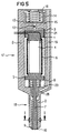
- FIG 3 shows an analog to the dosing device in Figure 1a Dosing device, in which the metal bellows 25 now by a Bourdon tube 6 is replaced.
- the PMA 4 is in direct Contact with the hydraulic fluid.
- the tubular spring 6 has the advantage over the metal bellows 25 that that it is comparatively inexpensive. especially one Slotted tubular spring can be easily produced in large numbers produce.
- Figure 4 shows a sectional side view Dosing device, in contrast to the dosing device in FIG. 1a, the compensation space 13 with the hydraulic space 3 is connected exclusively via a throttle bore 12.
- the viscosity of hydraulic fluids drops in automotive engineering relevant temperature range from -40 ° to + 150 ° Celsius typically by a factor of 20 to 50 for silicone oils and by a factor of up to 100,000 for mineral oils.
- the throttle bore 12 is preferably a micro bore with a typical for automotive applications Diameter between 10 ⁇ m and 50 ⁇ m. executed.
- Such Micro drilling can be done, for example, with the help of laser technology or by electrodeposition of nickel inside Existing holes are accurate and reproducible getting produced.
- Figure 5 shows a sectional side view of a Dosing device, in contrast to the dosing device in Figure 3, the compensation room 13 with the hydraulic room 3 exclusively connected via a throttled bore 12.
- the compensation space can of course 13 also outside the housing 2 as a separate, for. B. connected by means of fixed lines, chamber his.
- a piezo actuator 4 another electromechanical one can also be used Actuator, e.g. B. an electro- or magnetostrictive Actuator.
Abstract
Description
- der Aktor gegenüber dem zu dosierenden Fluid - im folgenden Dosierfluid genannt - geschützt ist,
- eine Zugspannung am Aktor vermieden wird,
- vorhandene Dichtelemente eine hohe mechanische Nachgiebigkeit in Bewegungsrichtung aufweisen, so daß eine Längenkompensation zum Ausgleich thermischer und druckbedingter Längenänderungen und zum Ausgleich herstellungsbedingter Längenstreuungen nicht behindert wird,
- eine hinreichende Druckfestigkeit der Dichtelemente gegeben ist,
- eine geeignete Kompensation druckbedingter Kräfte und/oder thermischer und/oder durch Alterungs- und Setzeffekte bedingter Kräfte bzw. Längenänderungen, zum Beispiel auf eine Ventilnadel, gegeben ist,
- eine hohe Zuverlässigkeit der Dichtelemente hinsichtlich einer Leckage garantiert ist,
- eine hydraulische Längenkompensation im typischen Temperaturintervall von -40° bis +150° Celsius gewährleistet ist.
- Figur 1a
- zeigt ein Dosierventil mit einem Piezoaktor, einer Ventilnadel und einem Hydraulikdämpfungssystem, wobei die Hydraulikkammer mit dem Aktorraum im verbunden ist,
- Figur 1b
- zeigt einen der in Figur 1a beschriebenen Dosiervorrichtung entsprechenden Querschnitt innerhalb einer Ventilkammer,
- die Figuren 2a und 2b
- zeigen Prinzipskizzen zur Definition von in dieser Beschreibung verwendeten Größen,
- Figur 3
- zeigt ein System entsprechend Figur 1, wobei im Gegensatz dazu die Ventilnadel und der Piezoaktor nicht fest miteinander verbunden sind,
- Figur 4
- zeigt ein Dosierventil entsprechend Figur 1, wobei die Verbindung zwischen der Hydraulikkammer und Ausgleichsraum über eine Systemdichtspalt-Ausgleichsbohrung geschieht,
- Figur 5
- zeigt ein System entsprechend Figur 1, wobei im Gegensatz dazu die Ventilnadel und der Piezoaktor nicht fest miteinander verbunden sind.
Zudem wird auf den Piezoaktor 4 eine hydraulische Druckkraft
Weiterhin wird durch den Vordruck eine kleine Menge der Hydraulikflüssigkeit, die während der Öffnungsphase des Dosierventils aus der Hydraulikkammer 3 durch die Drosselblende in den Ausgleichsraum 13 gedrängt wird, während der Phase, in der das Einspritzventil geschlossen ist, wieder zurück in die Hydraulikkammer 3 geführt. Dabei wird die Antriebseinheit wieder in die Ausgangsposition gebracht.
Claims (15)
wobei der Aktorraum (17), die Hydraulikkammer (3) und der Ausgleichsraum (13) mit einer unter Druck stehenden Hydraulikflüssigkeit gefüllt sind, derart, daß das System Hydraulikkammer (3)-Ausgleichsraum (13)- Aktorraum (17)- Hydraulikflüssigkeit ein dynamisch steifes Lager für den Piezoaktor (4) und ein Längenausgleichselement für zeitlich längere Vorgänge bildet.
wobei
Applications Claiming Priority (2)
| Application Number | Priority Date | Filing Date | Title |
|---|---|---|---|
| DE19940055A DE19940055C1 (de) | 1999-08-24 | 1999-08-24 | Dosierventil |
| DE19940055 | 1999-08-24 |
Publications (3)
| Publication Number | Publication Date |
|---|---|
| EP1079098A2 true EP1079098A2 (de) | 2001-02-28 |
| EP1079098A3 EP1079098A3 (de) | 2003-02-26 |
| EP1079098B1 EP1079098B1 (de) | 2004-05-26 |
Family
ID=7919395
Family Applications (1)
| Application Number | Title | Priority Date | Filing Date |
|---|---|---|---|
| EP00117809A Expired - Lifetime EP1079098B1 (de) | 1999-08-24 | 2000-08-18 | Dosiervorrichtung |
Country Status (3)
| Country | Link |
|---|---|
| EP (1) | EP1079098B1 (de) |
| DE (2) | DE19940055C1 (de) |
| ES (1) | ES2220305T3 (de) |
Cited By (19)
| Publication number | Priority date | Publication date | Assignee | Title |
|---|---|---|---|---|
| EP1167747A2 (de) * | 2000-06-26 | 2002-01-02 | Denso Corporation | Brennstoffeinspritzventil mit einem Piezoelektrischen Aktor |
| WO2003029641A2 (de) * | 2001-09-26 | 2003-04-10 | Henkel Loctite Deutschland Gmbh | Vorrichtung zur ventilbetätigung und zum stellen des ventilhubs |
| WO2003067071A1 (de) * | 2002-02-05 | 2003-08-14 | Robert Bosch Gmbh | Brennstoffeinspritzventil |
| FR2836536A1 (fr) * | 2002-02-26 | 2003-08-29 | Cedrat Technologies | Vanne piezoelectrique |
| WO2003089781A1 (de) * | 2002-04-22 | 2003-10-30 | Siemens Aktiengesellschaft | Dosiervorrichtung für fluide, insbesondere kraftfahrzeug-einspritzventil |
| EP1452729A1 (de) * | 2003-02-28 | 2004-09-01 | Robert Bosch Gmbh | Brennstoffeinspritzventil |
| WO2005026558A1 (de) * | 2003-09-12 | 2005-03-24 | Siemens Aktiengesellschaft | Hydrauliksystem mit ausgleichsspeicher |
| WO2008037625A1 (de) * | 2006-09-26 | 2008-04-03 | Siemens Aktiengesellschaft | Kapselung eines piezo-aktors |
| CN100416084C (zh) * | 2004-01-12 | 2008-09-03 | 西门子公司 | 带有用于补偿热性长度变化的机构的压电执行器以及带有压电执行器的燃料喷射阀 |
| WO2009059864A1 (de) * | 2007-11-09 | 2009-05-14 | Robert Bosch Gmbh | Piezoelektrisches aktormodul |
| KR100933626B1 (ko) * | 2001-11-30 | 2009-12-24 | 로베르트 보쉬 게엠베하 | 연료 분사 밸브 |
| WO2011045298A1 (de) * | 2009-10-12 | 2011-04-21 | Ulrich Stieler Kunststoff Service E.K. | Fluid-injektor |
| EP2317117A1 (de) * | 2009-11-03 | 2011-05-04 | Robert Bosch GmbH | Aktormodul und Brennstoffeinspritzventil |
| EP2414273A2 (de) * | 2009-04-03 | 2012-02-08 | KHS GmbH | Füllelement zum füllen von behältern mit einem flüssigen füllgut, füllmaschine sowie verfahren zum füllen von behältern |
| EP2846032A1 (de) * | 2013-09-09 | 2015-03-11 | Continental Automotive GmbH | Flüssigkeitseinspritzventil |
| WO2015055553A1 (en) * | 2013-10-14 | 2015-04-23 | Continental Automotive Gmbh | Injection valve |
| EP2944797A1 (de) * | 2014-05-07 | 2015-11-18 | Delphi International Operations Luxembourg S.à r.l. | Ventilaktuator eines kraftstoffinjektors |
| DE102015207170B3 (de) * | 2015-04-21 | 2016-09-29 | Festo Ag & Co. Kg | Fluidsystem |
| US11231001B2 (en) | 2013-10-04 | 2022-01-25 | Vitesco Technologies GmbH | Fuel injector |
Families Citing this family (25)
| Publication number | Priority date | Publication date | Assignee | Title |
|---|---|---|---|---|
| DE10035168A1 (de) * | 2000-07-19 | 2002-02-07 | Siemens Ag | Stellantrieb, Ventil sowie Verfahren zum Herstellen eines Stellantriebs |
| DE10211107A1 (de) * | 2001-07-12 | 2003-02-13 | Ceramtec Ag | Monolithischer Vielschichtaktor in einem Gehäuse |
| DE10139550A1 (de) * | 2001-08-10 | 2003-03-06 | Bosch Gmbh Robert | Hülse für ein Piezo-Aktormodul |
| DE10140197A1 (de) * | 2001-08-16 | 2003-03-13 | Bosch Gmbh Robert | Federhülse und Verfahren zur Herstellung einer Federhülse |
| DE10149914A1 (de) * | 2001-10-10 | 2003-04-24 | Bosch Gmbh Robert | Brennstoffeinspritzventil |
| DE10217594A1 (de) * | 2002-04-19 | 2003-11-06 | Bosch Gmbh Robert | Brennstoffeinspritzventil |
| DE10243147B4 (de) * | 2002-09-17 | 2006-03-16 | Siemens Ag | Verfahren zum Einbringen einer Lochkontur in ein Werkstück |
| DE10245109A1 (de) | 2002-09-27 | 2004-04-08 | Siemens Ag | Injektor, insbesondere Kraftstoff-Einspritzventil, mit einem piezoelektrischen Aktor |
| DE10307003B3 (de) * | 2003-02-19 | 2004-05-13 | Siemens Ag | Einspritzventil für die Einspritzung von Kraftstoff in eine Verbrennungskraftmaschine |
| WO2005026528A1 (de) | 2003-09-12 | 2005-03-24 | Siemens Aktiengesellschaft | Hydraulisches kompensationselement |
| DE10343017A1 (de) * | 2003-09-17 | 2005-04-14 | Robert Bosch Gmbh | Brennstoffeinspritzventil |
| DE10345203A1 (de) * | 2003-09-29 | 2005-05-04 | Bosch Gmbh Robert | Brennstoffeinspritzventil |
| DE102004001505B4 (de) * | 2004-01-09 | 2005-11-10 | Siemens Ag | Dosierventil mit Längenkompensationseinheit |
| DE102004048395B4 (de) * | 2004-10-05 | 2015-12-10 | Continental Automotive Gmbh | Piezo-Einspritzventil mit Kontaktelementen zur Wärmeableitung |
| DE102005043622A1 (de) * | 2005-09-13 | 2007-03-22 | Siemens Ag | Piezoelektrische Aktoreinheit bzw. piezoelektrische Antriebsvorrichtung |
| DE102005046949B3 (de) * | 2005-09-30 | 2007-04-05 | Siemens Ag | Dosierventil für Fluide, insbesondere Kraftfahrzeug-Einspritzventil |
| DE102006013510B4 (de) * | 2006-03-23 | 2008-08-14 | Siemens Ag | Drucktransfervorrichtung |
| DE102007038430A1 (de) | 2007-08-14 | 2009-02-19 | Robert Bosch Gmbh | Kraftstoffeinspritzventileinrichtung |
| DE102007056988B4 (de) * | 2007-11-27 | 2012-07-05 | Compact Dynamics Gmbh | Fluid-Einspritzventil mit Nadellängung |
| DE102010055417A1 (de) * | 2010-12-21 | 2012-06-21 | Hochschule Heilbronn | Elektromechanischer Energiespeicher, insbesondere für integrierte Schaltungen |
| DE102011084107A1 (de) * | 2011-10-06 | 2013-04-11 | Continental Automotive Gmbh | Piezoelektrischer Aktuator |
| DE102013006106A1 (de) * | 2013-04-09 | 2014-10-09 | Delo Industrie Klebstoffe Gmbh & Co. Kgaa | Dosiervorrichtung |
| DE102018108360A1 (de) * | 2018-04-09 | 2019-10-10 | Vermes Microdispensing GmbH | Dosiersystem mit piezokeramischem Aktor |
| DE102019101717B3 (de) | 2019-01-24 | 2020-07-09 | Universität des Saarlandes | Aktor |
| DE102021211437A1 (de) | 2021-10-11 | 2023-04-13 | Robert Bosch Gesellschaft mit beschränkter Haftung | Gasdosierventil |
Citations (4)
| Publication number | Priority date | Publication date | Assignee | Title |
|---|---|---|---|---|
| US4550744A (en) * | 1982-11-16 | 1985-11-05 | Nippon Soken, Inc. | Piezoelectric hydraulic control valve |
| DE4306072A1 (de) * | 1993-02-26 | 1994-09-08 | Siemens Ag | Vorrichtung zum Öffnen und Verschließen einer in einem Gehäuse vorhandenen Durchtrittsöffnung |
| DE19646847A1 (de) * | 1996-11-13 | 1997-06-12 | Heinz Schmidt | Anordnung eines modularen hydraulischen Stellwegtransformators mit variierbarem Übersetzungsverhältnis zur Übersetzung von Stellwagen von Festkörperenergiewandlern oder dergleichen |
| DE19727992A1 (de) * | 1997-07-01 | 1999-01-07 | Siemens Ag | Ausgleichselement zur Kompensation temperaturbedingter Längenänderung eines Objektes |
Family Cites Families (4)
| Publication number | Priority date | Publication date | Assignee | Title |
|---|---|---|---|---|
| DE2931874C2 (de) * | 1979-08-06 | 1983-08-04 | Audi Nsu Auto Union Ag, 7107 Neckarsulm | Elektrisch betätigbares Ventil |
| US4287578A (en) * | 1979-11-07 | 1981-09-01 | The United States Of America As Represented By The Administrator Of The National Aeronautics And Space Administration | Method for shaping and aiming narrow beams |
| DE4306073C1 (de) * | 1993-02-26 | 1994-06-01 | Siemens Ag | Zumeßvorrichtung für Fluide |
| DE19727982A1 (de) * | 1997-07-01 | 1999-01-07 | Hella Kg Hueck & Co | Leuchte für Fahrzeuge |
-
1999
- 1999-08-24 DE DE19940055A patent/DE19940055C1/de not_active Expired - Fee Related
-
2000
- 2000-08-18 ES ES00117809T patent/ES2220305T3/es not_active Expired - Lifetime
- 2000-08-18 DE DE50006571T patent/DE50006571D1/de not_active Expired - Fee Related
- 2000-08-18 EP EP00117809A patent/EP1079098B1/de not_active Expired - Lifetime
Patent Citations (4)
| Publication number | Priority date | Publication date | Assignee | Title |
|---|---|---|---|---|
| US4550744A (en) * | 1982-11-16 | 1985-11-05 | Nippon Soken, Inc. | Piezoelectric hydraulic control valve |
| DE4306072A1 (de) * | 1993-02-26 | 1994-09-08 | Siemens Ag | Vorrichtung zum Öffnen und Verschließen einer in einem Gehäuse vorhandenen Durchtrittsöffnung |
| DE19646847A1 (de) * | 1996-11-13 | 1997-06-12 | Heinz Schmidt | Anordnung eines modularen hydraulischen Stellwegtransformators mit variierbarem Übersetzungsverhältnis zur Übersetzung von Stellwagen von Festkörperenergiewandlern oder dergleichen |
| DE19727992A1 (de) * | 1997-07-01 | 1999-01-07 | Siemens Ag | Ausgleichselement zur Kompensation temperaturbedingter Längenänderung eines Objektes |
Cited By (28)
| Publication number | Priority date | Publication date | Assignee | Title |
|---|---|---|---|---|
| EP1167747A3 (de) * | 2000-06-26 | 2003-04-09 | Denso Corporation | Brennstoffeinspritzventil mit einem Piezoelektrischen Aktor |
| EP1167747A2 (de) * | 2000-06-26 | 2002-01-02 | Denso Corporation | Brennstoffeinspritzventil mit einem Piezoelektrischen Aktor |
| WO2003029641A2 (de) * | 2001-09-26 | 2003-04-10 | Henkel Loctite Deutschland Gmbh | Vorrichtung zur ventilbetätigung und zum stellen des ventilhubs |
| WO2003029641A3 (de) * | 2001-09-26 | 2003-09-12 | Henkel Loctite Deutschland Gmb | Vorrichtung zur ventilbetätigung und zum stellen des ventilhubs |
| KR100933626B1 (ko) * | 2001-11-30 | 2009-12-24 | 로베르트 보쉬 게엠베하 | 연료 분사 밸브 |
| WO2003067071A1 (de) * | 2002-02-05 | 2003-08-14 | Robert Bosch Gmbh | Brennstoffeinspritzventil |
| US7083114B2 (en) | 2002-02-05 | 2006-08-01 | Robert Bosch Gmbh | Fuel injector |
| US6994110B2 (en) | 2002-02-26 | 2006-02-07 | Cedrat Technologies | Piezoelectric valve |
| FR2836536A1 (fr) * | 2002-02-26 | 2003-08-29 | Cedrat Technologies | Vanne piezoelectrique |
| WO2003089781A1 (de) * | 2002-04-22 | 2003-10-30 | Siemens Aktiengesellschaft | Dosiervorrichtung für fluide, insbesondere kraftfahrzeug-einspritzventil |
| US7309032B2 (en) | 2002-04-22 | 2007-12-18 | Siemens Aktiengesellschaft | Dosing device for fluids, especially a motor vehicle injection valve |
| EP1452729A1 (de) * | 2003-02-28 | 2004-09-01 | Robert Bosch Gmbh | Brennstoffeinspritzventil |
| WO2005026558A1 (de) * | 2003-09-12 | 2005-03-24 | Siemens Aktiengesellschaft | Hydrauliksystem mit ausgleichsspeicher |
| CN100416084C (zh) * | 2004-01-12 | 2008-09-03 | 西门子公司 | 带有用于补偿热性长度变化的机构的压电执行器以及带有压电执行器的燃料喷射阀 |
| WO2008037625A1 (de) * | 2006-09-26 | 2008-04-03 | Siemens Aktiengesellschaft | Kapselung eines piezo-aktors |
| WO2009059864A1 (de) * | 2007-11-09 | 2009-05-14 | Robert Bosch Gmbh | Piezoelektrisches aktormodul |
| EP2414273A2 (de) * | 2009-04-03 | 2012-02-08 | KHS GmbH | Füllelement zum füllen von behältern mit einem flüssigen füllgut, füllmaschine sowie verfahren zum füllen von behältern |
| WO2011045298A1 (de) * | 2009-10-12 | 2011-04-21 | Ulrich Stieler Kunststoff Service E.K. | Fluid-injektor |
| EP2317117A1 (de) * | 2009-11-03 | 2011-05-04 | Robert Bosch GmbH | Aktormodul und Brennstoffeinspritzventil |
| EP2846032A1 (de) * | 2013-09-09 | 2015-03-11 | Continental Automotive GmbH | Flüssigkeitseinspritzventil |
| CN104421084A (zh) * | 2013-09-09 | 2015-03-18 | 大陆汽车有限公司 | 流体喷射阀 |
| CN104421084B (zh) * | 2013-09-09 | 2018-03-13 | 大陆汽车有限公司 | 流体喷射阀 |
| US11231001B2 (en) | 2013-10-04 | 2022-01-25 | Vitesco Technologies GmbH | Fuel injector |
| WO2015055553A1 (en) * | 2013-10-14 | 2015-04-23 | Continental Automotive Gmbh | Injection valve |
| CN105849403A (zh) * | 2013-10-14 | 2016-08-10 | 大陆汽车有限公司 | 喷射阀 |
| US10094350B2 (en) | 2013-10-14 | 2018-10-09 | Continental Automotive Gmbh | Injection valve |
| EP2944797A1 (de) * | 2014-05-07 | 2015-11-18 | Delphi International Operations Luxembourg S.à r.l. | Ventilaktuator eines kraftstoffinjektors |
| DE102015207170B3 (de) * | 2015-04-21 | 2016-09-29 | Festo Ag & Co. Kg | Fluidsystem |
Also Published As
| Publication number | Publication date |
|---|---|
| DE19940055C1 (de) | 2001-04-05 |
| EP1079098B1 (de) | 2004-05-26 |
| DE50006571D1 (de) | 2004-07-01 |
| ES2220305T3 (es) | 2004-12-16 |
| EP1079098A3 (de) | 2003-02-26 |
Similar Documents
| Publication | Publication Date | Title |
|---|---|---|
| EP1079098B1 (de) | Dosiervorrichtung | |
| EP1497553B1 (de) | Dosiervorrichtung für fluide, insbesondere kraftfahrzeug-einspritzventil | |
| EP1079099B1 (de) | Einspritzventil | |
| DE60121352T2 (de) | Ausgleichvorrichtung mit einer flexiblen membran für ein kraftstoffeinspritzventil und verfahren dafür | |
| DE19712921A1 (de) | Brennstoffeinspritzventil mit piezoelektrischem oder magnetostriktivem Aktor | |
| DE112010001987T5 (de) | Piezoelektrische direkt wirkende Kraftstoff-E inspritzdüse mit Hydraulikverbindung | |
| EP1079158A2 (de) | Dosiervorrichtung und Verfahren zur Dosierung | |
| EP0795081B1 (de) | Elektrohydraulischer antrieb | |
| DE19727992A1 (de) | Ausgleichselement zur Kompensation temperaturbedingter Längenänderung eines Objektes | |
| EP2414662A1 (de) | Hydraulischer hubübertrager | |
| DE10019764B4 (de) | Ventil zum Steuern von Flüssigkeiten | |
| DE10217594A1 (de) | Brennstoffeinspritzventil | |
| DE102004001505B4 (de) | Dosierventil mit Längenkompensationseinheit | |
| DE102005045893A1 (de) | Hydraulische Kompensationseinrichtung | |
| EP1431568A2 (de) | Brennstoffeinspritzventil | |
| DE102006013510B4 (de) | Drucktransfervorrichtung | |
| EP1664525B1 (de) | Dosiervorrichtung | |
| DE102005046778B4 (de) | Dosiervorrichtung für Fluide, insbesondere Kraftfahrzeug-Einspritzventil | |
| DE102004060533A1 (de) | Brennstoffeinspritzventil | |
| EP1317621A1 (de) | Hydraulisch übersetztes ventil | |
| DE102005046949B3 (de) | Dosierventil für Fluide, insbesondere Kraftfahrzeug-Einspritzventil | |
| DE102005029473A1 (de) | Kraftstoffinjektor | |
| DE10343488A1 (de) | Hydrauliksystem mit Ausgleichsspeicher | |
| WO2004085831A1 (de) | Dosierventil mit längenkompensationseinheit | |
| EP1526275B1 (de) | Brennstoffeinspritzventil |
Legal Events
| Date | Code | Title | Description |
|---|---|---|---|
| PUAI | Public reference made under article 153(3) epc to a published international application that has entered the european phase |
Free format text: ORIGINAL CODE: 0009012 |
|
| AK | Designated contracting states |
Kind code of ref document: A2 Designated state(s): AT BE CH CY DE DK ES FI FR GB GR IE IT LI LU MC NL PT SE |
|
| AX | Request for extension of the european patent |
Free format text: AL;LT;LV;MK;RO;SI |
|
| PUAL | Search report despatched |
Free format text: ORIGINAL CODE: 0009013 |
|
| AK | Designated contracting states |
Kind code of ref document: A3 Designated state(s): AT BE CH CY DE DK ES FI FR GB GR IE IT LI LU MC NL PT SE |
|
| AX | Request for extension of the european patent |
Extension state: AL LT LV MK RO SI |
|
| RIC1 | Information provided on ipc code assigned before grant |
Ipc: 7F 02M 51/06 A Ipc: 7F 16K 31/00 B Ipc: 7F 02M 61/08 B Ipc: 7F 02M 59/46 B Ipc: 7F 02M 61/16 B |
|
| 17P | Request for examination filed |
Effective date: 20030407 |
|
| AKX | Designation fees paid |
Designated state(s): DE ES FR GB IT |
|
| GRAP | Despatch of communication of intention to grant a patent |
Free format text: ORIGINAL CODE: EPIDOSNIGR1 |
|
| GRAS | Grant fee paid |
Free format text: ORIGINAL CODE: EPIDOSNIGR3 |
|
| GRAA | (expected) grant |
Free format text: ORIGINAL CODE: 0009210 |
|
| AK | Designated contracting states |
Kind code of ref document: B1 Designated state(s): DE ES FR GB IT |
|
| REG | Reference to a national code |
Ref country code: GB Ref legal event code: FG4D Free format text: NOT ENGLISH |
|
| GBT | Gb: translation of ep patent filed (gb section 77(6)(a)/1977) |
Effective date: 20040526 |
|
| REG | Reference to a national code |
Ref country code: IE Ref legal event code: FG4D Free format text: GERMAN |
|
| REF | Corresponds to: |
Ref document number: 50006571 Country of ref document: DE Date of ref document: 20040701 Kind code of ref document: P |
|
| REG | Reference to a national code |
Ref country code: ES Ref legal event code: FG2A Ref document number: 2220305 Country of ref document: ES Kind code of ref document: T3 |
|
| REG | Reference to a national code |
Ref country code: IE Ref legal event code: FD4D |
|
| ET | Fr: translation filed | ||
| PLBE | No opposition filed within time limit |
Free format text: ORIGINAL CODE: 0009261 |
|
| STAA | Information on the status of an ep patent application or granted ep patent |
Free format text: STATUS: NO OPPOSITION FILED WITHIN TIME LIMIT |
|
| 26N | No opposition filed |
Effective date: 20050301 |
|
| PGFP | Annual fee paid to national office [announced via postgrant information from national office to epo] |
Ref country code: ES Payment date: 20070917 Year of fee payment: 8 |
|
| PGFP | Annual fee paid to national office [announced via postgrant information from national office to epo] |
Ref country code: GB Payment date: 20070808 Year of fee payment: 8 |
|
| PGFP | Annual fee paid to national office [announced via postgrant information from national office to epo] |
Ref country code: DE Payment date: 20071022 Year of fee payment: 8 Ref country code: IT Payment date: 20070829 Year of fee payment: 8 |
|
| PGFP | Annual fee paid to national office [announced via postgrant information from national office to epo] |
Ref country code: FR Payment date: 20070828 Year of fee payment: 8 |
|
| GBPC | Gb: european patent ceased through non-payment of renewal fee |
Effective date: 20080818 |
|
| REG | Reference to a national code |
Ref country code: FR Ref legal event code: ST Effective date: 20090430 |
|
| PG25 | Lapsed in a contracting state [announced via postgrant information from national office to epo] |
Ref country code: FR Free format text: LAPSE BECAUSE OF NON-PAYMENT OF DUE FEES Effective date: 20080901 Ref country code: IT Free format text: LAPSE BECAUSE OF NON-PAYMENT OF DUE FEES Effective date: 20080818 Ref country code: DE Free format text: LAPSE BECAUSE OF NON-PAYMENT OF DUE FEES Effective date: 20090303 |
|
| REG | Reference to a national code |
Ref country code: ES Ref legal event code: FD2A Effective date: 20080819 |
|
| PG25 | Lapsed in a contracting state [announced via postgrant information from national office to epo] |
Ref country code: GB Free format text: LAPSE BECAUSE OF NON-PAYMENT OF DUE FEES Effective date: 20080818 |
|
| PG25 | Lapsed in a contracting state [announced via postgrant information from national office to epo] |
Ref country code: ES Free format text: LAPSE BECAUSE OF NON-PAYMENT OF DUE FEES Effective date: 20080819 |