EP1077785B2 - Vorrichtung und verfahren zum miteinander schweissen von röhren - Google Patents
Vorrichtung und verfahren zum miteinander schweissen von röhren Download PDFInfo
- Publication number
- EP1077785B2 EP1077785B2 EP99967025A EP99967025A EP1077785B2 EP 1077785 B2 EP1077785 B2 EP 1077785B2 EP 99967025 A EP99967025 A EP 99967025A EP 99967025 A EP99967025 A EP 99967025A EP 1077785 B2 EP1077785 B2 EP 1077785B2
- Authority
- EP
- European Patent Office
- Prior art keywords
- welding
- pipes
- torches
- groove
- torch
- Prior art date
- Legal status (The legal status is an assumption and is not a legal conclusion. Google has not performed a legal analysis and makes no representation as to the accuracy of the status listed.)
- Expired - Lifetime
Links
Images

Classifications
-
- B—PERFORMING OPERATIONS; TRANSPORTING
- B23—MACHINE TOOLS; METAL-WORKING NOT OTHERWISE PROVIDED FOR
- B23K—SOLDERING OR UNSOLDERING; WELDING; CLADDING OR PLATING BY SOLDERING OR WELDING; CUTTING BY APPLYING HEAT LOCALLY, e.g. FLAME CUTTING; WORKING BY LASER BEAM
- B23K9/00—Arc welding or cutting
- B23K9/12—Automatic feeding or moving of electrodes or work for spot or seam welding or cutting
- B23K9/127—Means for tracking lines during arc welding or cutting
- B23K9/1272—Geometry oriented, e.g. beam optical trading
- B23K9/1276—Using non-contact, electric or magnetic means, e.g. inductive means
-
- B—PERFORMING OPERATIONS; TRANSPORTING
- B23—MACHINE TOOLS; METAL-WORKING NOT OTHERWISE PROVIDED FOR
- B23K—SOLDERING OR UNSOLDERING; WELDING; CLADDING OR PLATING BY SOLDERING OR WELDING; CUTTING BY APPLYING HEAT LOCALLY, e.g. FLAME CUTTING; WORKING BY LASER BEAM
- B23K9/00—Arc welding or cutting
- B23K9/02—Seam welding; Backing means; Inserts
- B23K9/028—Seam welding; Backing means; Inserts for curved planar seams
- B23K9/0282—Seam welding; Backing means; Inserts for curved planar seams for welding tube sections
- B23K9/0286—Seam welding; Backing means; Inserts for curved planar seams for welding tube sections with an electrode moving around the fixed tube during the welding operation
-
- B—PERFORMING OPERATIONS; TRANSPORTING
- B23—MACHINE TOOLS; METAL-WORKING NOT OTHERWISE PROVIDED FOR
- B23K—SOLDERING OR UNSOLDERING; WELDING; CLADDING OR PLATING BY SOLDERING OR WELDING; CUTTING BY APPLYING HEAT LOCALLY, e.g. FLAME CUTTING; WORKING BY LASER BEAM
- B23K2101/00—Articles made by soldering, welding or cutting
- B23K2101/04—Tubular or hollow articles
- B23K2101/06—Tubes
Definitions
- the present invention relates to an apparatus and method for welding pipes together. More specifically the invention relates to arc-welding together pipe sections when laying deep-sea pipelines (i.e. underwater pipelines).
- the welding process used when laying such pipelines is commonly of the type where a continuous-wire arc welding torch is used.
- the pipe sections may consist of a plurality of pipe lengths each welded together on the lay-barge to form the pipe sections when required.
- the radial distance of the electrode with respect to the pipes must change in relation to the depth of the weld joint. As the region of the joint between the pipes is filled with welded metal the surface of the welded metal gets closer to the welding torch.
- a known method of welding two pipes together may be described as follows.
- the pipes to be joined are prepared prior to the welding process by bevelling the ends of the pipes such that when the pipes are arranged immediately before the welding process commences (coaxially with respect to each other), an exterior circumferential groove is defined between the two pipes.
- the pipes are positioned ready for welding.
- a carriage is mounted on one of the pipes for movement around the circumference of the pipes to be joined.
- a welding torch is mounted on the carriage and the apparatus is so arranged that the end of the metal electrode of the torch is opposite and relatively close to the circumferential groove.
- the carriage is moved around the circumference of the pipe and the torch is operated so that an arc is directed into the groove.
- the arc is guided manually and/or by various mechanical sensors to guide the arc as accurately as possible along the length of the groove.
- the welding process generally takes several passes.
- the resolution of the mechanical sensors is such that a human operator is required to assist in the welding process for guiding the arc with sufficient accuracy.
- US 4,283,617 discloses an apparatus and method for automatically welding together pipe sections according to the preamble of claim 1.
- the apparatus includes a torch transport assembly for moving two torches along the circumferential joint to be welded between the pipe sections. The two torches are separated by a distance equivalent to one quarter of the circumference of the pipe sections.
- Other welding apparatus/methods are described in US 4,485,291 and US 4,631,386 .
- An object of the present invention is to provide an apparatus and method for welding pipes together that mitigates at least some of the above-mentioned disadvantages associated with the known method and apparatus described above.
- a further object of the present invention is to provide an apparatus and method for welding pipes together that is faster at welding pipes together than the known method and apparatus described above but without significantly reducing the quality of weld joint.
- the present invention provides a method of forming a pipeline including a step of welding two pipe together, said step of welding two pipes together comprising the steps of
- the automatic electronic guidance of the welding enables the method of the present invention to be used to weld pipes together, where the angle of separation of the walls defining the groove is less than 10 degrees.
- the angle of separation of the walls defining the groove is advantageously 6 degrees or less. Generally, the narrower the angle, the less weld material is required to weld the pipes together satisfactorily.
- the walls defining the groove may even be substantially parallel.
- a first torch When the torches are first operated to form a weld, it is preferable for a first torch to start welding and for other torches to start welding only once they have reached the position at which the first torch was started.
- the torches may be shut down in order in a similar manner.
- the automation of the guiding of the welding torches according to the present invention facilitates the provision of a plurality of such torches mounted on a single carriage. If the guiding of the torches were not fully automated, a plurality of operators might be required in respect of a single carriage. Furthermore the method of automatically guiding the torches according to the present invention does not require mechanical contact with the walls that define the groove and has been found to be highly accurate, which could lead to fewer welds being rejected, when subjected to the rigorous quality testing necessary when laying pipelines.
- the guidance of the arcs is effected without any mechanical or optical sensors.
- the axes of the torches may be substantially parallel.
- the axes of the torches may be arranged so that, in use, they each extend substantially radially with respect to the pipe.
- the guidance of the arcs can be, and preferably is, effected by a carriage moving circumferentially around the pipes and along the groove so that the torch points generally towards the groove and a control unit controls the exact position of the arcs by effecting correcting movements to the torch in a direction parallel to the axis of the pipe.
- Such correcting movements preferably, but not necessarily, move the arc to substantially the exact desired location.
- the process of automatically guiding the arcs includes a step of ascertaining the difference between a value representing an electrical characteristic relating to one pipe and a value representing the same electrical characteristic relating to the other pipe and then performing a correcting movement in which the position of the arc is moved in dependence on the value of the difference.
- the position of the arc may be moved a preset distance (for example, in a direction along the axis of the pipe) if the value of the difference is outside a predetermined range of acceptable values.
- the direction of the movement may depend on whether the value of the difference is above a high threshold value or below a low threshold value.
- the magnitude of the correcting movement could depend on the value of the difference.
- the measurements, from which the values of the electrical characteristics compared are ascertained, are of course preferably taken with the arc being at substantially the same distance along the length of the groove.
- the method therefore preferably further comprises monitoring the values of the differences over time and if the values of the differences are indicative of the arc being substantially continuously to one side of the desired path a correcting movement of the arc is effected.
- an integrating device might be provided to calculate a running sum of the values of the calculated differences.
- the electrical characteristics that are ascertained may include one or more of voltage, potential difference, current, current intensity and arc impedance.
- the characteristics are preferably ascertained by measuring electrical characteristics of the arcs of the welding torches.
- the torches need not all be operated in the same manner. Some torches may be operated at different currents for example. Two of the torches effecting welding of the pipe weld at different rates. For example, one torch may be fed with welding wire at a different rate.
- each torch is a continuous wire arc welding torch.
- the wire is fed into the torch and, by means of the arc welding process, fills the groove between the pipes to form the weld joint.
- the supply of the wire is advantageously mounted remotely from the carriage. Having the supply of wire being remotely provided makes the carriage lighter and consequently easier to operate.
- the wire may be mounted on a spool. A typical spool of wire can weigh about 2.5Kg.
- each torch is movable independently in a direction having a component parallel to the axis of the pipe.
- a suitable method of ascertaining the necessary values of the electrical characteristics relating to each respective pipe is described below.
- a step of that method preferably includes oscillating each welding torch so that the position of each arc alternatively moves from one side to the other of the general path being traced along the groove by each respective torch.
- the torches are thus preferably moved so that the respective positions of the arcs within the groove oscillate between the walls defining the groove.
- Each welding torch is preferably oscillated so that the position of each arc alternatively moves generally towards and away from the walls of the groove.
- the oscillatory movement of each arc is preferably in a direction having a component in a direction along the axis of the pipe.
- the direction of the oscillatory movement is substantially perpendicular to the length of the groove.
- the direction of the oscillatory movement is substantially parallel to the axis of the pipe.
- the oscillatory movement of the arcs towards and away from the walls of the groove is advantageously small in comparison to the width of the weld layer being deposited at a given time.
- the amplitude of the oscillatory movement is advantageously so small that the quality of the weld being formed is not significantly affected.
- the amplitude of the oscillations of the arc may, during at least some stage in the welding process, be less than a tenth of a millimetre.
- the step of ascertaining the electrical characteristics of the welding with regard to each pipe preferably includes a step of oscillating the position of the arcs in the groove. Since the electrical characteristics of an arc change in dependence upon the relative position of the arc in the groove, an indication of the position of the arc within the groove can be ascertained, by observing and comparing the electrical characteristics of the arc, as the distance of the arc from the walls changes.
- each torch in said direction having a component parallel to the axis of the pipe is preferably driven by a respective independent prime mover.
- a single prime mover preferably effects motion of the torches along the length of the groove.
- the or each prime mover may be an electric motor, preferably a brushless electric motor.
- each torch is cooled during operation.
- each torch may be provided with means for cooling the torch during operation.
- the torches are each water cooled.
- the water cooling system of a torch effects cooling of the welding tip of that torch.
- the invention also provides a method as described above, wherein the pipes are of a size and have a wall thickness suitable for forming a deep sea pipeline, and the pipes are joined by butt welding effected by an automatically guiding welding apparatus, the method comprising the steps of
- the present invention also provides a method of constructing an underwater pipeline including using the method according to the present invention as described herein.
- the technique used in laying the underwater pipeline may be the J-lay method.
- one of the two pipes will be the pipe section and the other will of course be the free end of the pipeline to which the pipe section is to be connected.
- the pipe section Whilst in the case where a pipe section is to be welded to a pipeline it is necessary for the pipe section to be prevented from rotating, at least some of the features of the present invention can, of course, also be of use when welding pipes together, such as for example when welding pipe lengths together to form a pipe section, where it is possible for the pipes to rotate and for the welding apparatus to remain stationary.
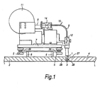
- FIG 1 shows in partial cross-section the ends of the pipes 2, 4 to be welded together and a schematic side view of a welding apparatus 10 having two voltaic arc-welding torches 1 (only one of which can be seen in Figure 1) for butt welding the pipes 2, 4 together.
- the welding torch is of the well known GMAW (gas metal arc welding) and can either be of the type used in MAG (metal active gas) welding or of the type used in MIG (metal inert gas) welding.
- the gas used may for example be carbon dioxide.
- the pipes 2, 4 are arranged with their axes aligned and their ends 26, 27 next to each other.
- the ends 26, 27 of the pipes are bevelled so that when brought together they define a circumferentially extending exterior groove 28.
- a track 6 is fixedly mounted as a single unit on the left hand pipe 2 (as viewed in Figure 1).
- the track 6 extends circumferentially around the pipe 2.
- the track 6 has two guide tracks 29, 30 that extend around the pipe 2.
- the welding apparatus 10 is mounted for movement along the track 6.
- Wheels 5 are rotatably mounted on a base plate 7 of the welding apparatus 10. The wheels 5 engage with the guide tracks 29, 30 and facilitate the guided movement of the apparatus 10 along the track 6.
- One of the tracks 30 also provides a toothed rack that extends around the pipe.
- a pinion wheel (not shown), mounted for engagement with the rack, is driven so that the apparatus may be driven around the pipe 2.
- the driven pinion wheel may be rotated via a driven chain, which is in turn driven by a stepper motor, or similar driving source (not illustrated).
- the track 6 is so positioned on the pipe 2 that the torches 1 of the apparatus 10 are each positioned directly over the groove 28.
- Such methods of positioning a track and a welding apparatus on a pipe so that a torch of the welding apparatus is correctly positioned over the weld joint to be formed are well known and are therefore not described here in further detail.
- the apparatus 10 is driven around the pipes 2, 4 and the welding torches 1 are operated and controlled so that they deposit weld material in the centre of the groove 28 to form a weld joint 3.
- the weld torches are arranged next to each other.
- the apparatus is started up the first torch (the torch at the front in respect of the initial direction of motion of the torches) is operated first and the other torch is not operated until it reaches the start of the weld laid down by the first torch.
- weld material is deposited in the groove by the first torch to form the weld joint 3 and shortly thereafter further weld material is deposited on top of the weld joint 3 by the second torch.
- the apparatus 10 performs several passes depositing further layers of weld material in the groove to join the pipes together.
- the welding apparatus 10 rotates in both directions around the circumference of the pipes 2, 4.
- the welding apparatus 10 moves around the pipes 2, 4 in one direction (i.e. clockwise or anticlockwise) until it has moved around the entire circumference of the pipes at least once.
- Both torches 1 function in a similar way.
- the following description relates to only one of the two torches and its guidance system, but it will be understood that the other torch functions in substantially the same way.
- Welding wire 9 is continuously fed from a spool 11 of wire to the torch 1.
- the welding wire 9 is unwound from the wire spool 11 by means of a pulling device 14 which conveys the wire 9 via a guiding pipe 8 to a straining device 12, from where the wire is fed into the torch 1.
- the welding of the pipes 2 and 4, by the welding torch is controlled by an automatic guidance system.
- the guidance system guides the welding torch by ascertaining electrical parameter values relating to the voltaic arc impedance.
- the arc impedance depends on, inter alia, the position of the welding arc in relation to the walls defining the groove 28. If the arc lies in the notional central plane (containing the centre line of the groove 28) halfway between the walls of the groove 28, then the influence of those walls on the above electrical parameters is practically identical. On the other hand, if the arc of the voltaic torch 1 is not positioned directly in the centre of the groove 28 the influence of the walls of the groove on the electrical parameter values will be different.
- Monitoring the magnitudes of an electrical parameter ascertained enables the control unit (not shown in Figure 1) of the apparatus to calculate the deviation from the central position of the arc of the torch 1 in the groove 28. More specifically the magnitude of the values of voltage, current and impedance (V, I, R) relating to one wall of the groove 28 are compared with those relating to the other wall of the groove, during the continuous movement of the torch 1. The voltage and current of the arc is measured with equipment attached to or in the welding torch and the arc impedance can then be calculated using those measured values. The method of ascertaining those values in respect of a given wall of the groove 28 is explained below with reference to Figure 2.
- FIG. 2 illustrates schematically the automatic guidance system of the welding apparatus according to the first embodiment (illustrated by Figure 1) of the present invention.
- Each torch is provided with a guidance system, but the system is illustrated and described with reference to a single torch only for the sake of simplicity.
- the guidance system periodically ascertains the electrical parameter values of voltage, current intensity and voltaic arc impedance relating to the right wall and left wall which define the groove 28 (see Figure 1).
- the welding torch is oscillated so that the position of the arc oscillates with a small amplitude in a direction substantially parallel to the axis of the pipe (so that the arc moves towards and away from each wall).
- the arc voltage and current are measured practically continuously and signals corresponding to those measured values are passed from the torch 1 via a cable 25 to a governing unit 15.
- the governing unit 15 includes a processing means, which processes the signals.
- the governing unit 15 sends signals representative of the electrical parameter values measured for the left and right walls to two digital filters 16, 18, one filter 16 for generating signals relating to the right wall and one filter 18 for the left wall.
- the governing unit 15 and filters 16, 18 are thus able effectively to extract, from the signals from the torch 1, signals corresponding to values of the parameters measured in respect of the arc in relation to the left wall and right wall, respectively, of the groove 28.
- Output signals are thus produced by the filters 16, 18 relating to the voltage, current and impedance values relating to their respective wall of the groove.
- a difference unit 19 calculates an indication of the position in the groove of the arc of the torch by calculating the differences in the values relating to the left and right walls respectively, determined from the signals received from the filters 16, 18. The calculations, which are made practically continuously, are used in real time for controlling the position and orientation of the torch 1 in relation to the groove 28.
- a signal is generated which causes a gain unit 21 to activate a command signal, which by means of an amplifier 22, causes a drive unit 23 in association with a centring regulation unit 24 to move the welding torch 1, so that the arc is moved towards the desired location (the centre line of the groove).
- the gain unit 21 does not cause the torch to be moved.
- signals representing the difference values calculated by the difference unit 19 are sent to an integrator unit 20 that is also provided to regulate the positioning of the torch 1 during the welding process. If the position of the arc remains near the central line of the groove 28, and the sum of the distances to the left of the line is practically equal, over time, to the sum of the distances to the right of the line the integrator 20 will not generate any centring movement command signal through the amplifier 22.
- the integrator 20 activates a command signal, which by means of the amplifier 22, causes the drive unit 23 and centring regulation unit 24 to move the welding torch 1, so that the arc is moved towards the desired location (the centre line of the groove).
- the calculations performed by the automatic guidance system may include performing comparisons between calculated values relating to the actual state of the welding system and sample values held in the memory of the guidance system. Such sample values may be entered into the memory manually by keyboard.
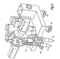
- FIG 3 shows schematically a welding apparatus 110 according to a second embodiment of the present invention in perspective view.
- the apparatus operates in a similar manner to that of the first embodiment described above.
- the welding torches 101 are aligned so that when the apparatus 110 is mounted on a pipe (not shown in Fig.3) they both point towards the same notional circumferential line extending around the pipe.
- Wheels 105 are provided for engaging with a guide track (not shown in Fig.3) that, in use, extends around one of the pipes to be welded.
- the welding wire (not shown) of the second embodiment is not provided on the movable welding apparatus 110, rather it is mounted at a location remote from the apparatus, and fed from that remote location, via a guide pipe, to the welding apparatus as it moves around the pipe. It is therefore useful that the apparatus is able to move both clockwise and anticlockwise around the pipe, to reduce the chance of the welding wire becoming twisted.
- the torches 101 are each water cooled.
- the water is pumped around a cooling system (not shown) including parts of the torch.
- the water heated by the operating torch passes into a heat exchanger, such as a radiator, so that it is cooled.
Claims (20)
- Verfahren zum Herstellen einer Rohrleitung, das einen Schritt des Verschweißens zweier Rohre (2, 4) miteinander umfaßt, wobei der Schritt des Verschweißens zweier Rohre (2, 4) miteinander die folgenden Schritte umfaßt:Anordnen zweier Rohre (2, 4) Ende (26) an Ende (27), wobei die Rohre (2, 4) so geformt sind, daß zwischen den Enden (26, 27) der Rohre (2, 4) eine in Umfangsrichtung verlaufende Nut (28) definiert ist,Ausführen einer Relativbewegung einer Vielzahl von auf einem einzelnen Schlitten (10) angeordneter Lichtbogen-Schweißbrenner (1) mit im wesentlichen der gleichen Geschwindigkeit um die Rohre (2, 4),und Betreiben der mehreren Lichtbogen-Schweißbrenner (1), so daß ihre Lichtbögen in der Nut (28) eine Schweißnaht (3) bilden,
dadurch gekennzeichnet, daßdie gebildete Rohrleitung eine Tiefsee-Pipeline ist,der Trennwinkel der Wandungen, die die Nut (28) zwischen den Rohren (2, 4) definieren, kleiner als 10 Grad ist,wenigstens zwei Brenner (1) der Vielzahl von Lichtbogen-Schweißbrennern (1) direkt nebeneinander angeordnet sind, so daß während des Betriebs der Brenner (1) die Lichtbögen der wenigstens zwei Brenner (1) in der Nut (28) direkt nacheinander erzeugt werden,zwei der Brenner (1), die ein Verschweißen des Rohrs (2, 4) ausführen, mit unterschiedlichen Geschwindigkeiten schweißen, undder durch jeden der mehreren Lichtbogen-Schweißbrenner (1) erzeugte Lichtbogen unabhängig automatisch elektronisch geführt wird, indem die elektrischen Eigenschaften des Schweißvorgangs für jedes Rohr (2, 4) bestimmt werden (15) und die elektrischen Eigenschaften in bezug auf eines der Rohre (2, 4) mit den entsprechenden elektrischen Eigenschaften in bezug auf das andere der Rohre (2, 4) verglichen werden (19). - Verfahren nach Anspruch 1, bei dem die Achsen der wenigstens zwei Brenner (1), die direkt nebeneinander angeordnet sind, im wesentlichen parallel sind.
- Verfahren nach Anspruch 1 oder Anspruch 2, bei dem die mehreren Lichtbogen-Schweißbrenner (1) GMAW-Brenner (Gas-Metall-Lichtbogen-Schweißbrenner) sind.
- Verfahren nach einem vorhergehenden Anspruch, bei dem die mehreren Lichtbogen-Schweißbrenner (1) unter Verwendung eines MAG-Schweißprozesses (Metall-Aktivgas-Schweißprozeß) betrieben werden.
- Verfahren nach einem vorhergehenden Anspruch, das den Schritt des Bestimmens der Differenz zwischen einem Wert, der eine elektrische Eigenschaft in bezug auf ein Rohr (2, 4) repräsentiert, und einem Wert, der die gleiche elektrische Eigenschaft in bezug auf das andere Rohr (2, 4) repräsentiert, und des anschließenden Ausführens einer Korrekturbewegung, die die Position des Lichtbogens in Abhängigkeit vom Differenzwert bewegt, umfaßt.
- Verfahren nach Anspruch 5, bei dem eine Korrekturbewegung ausgeführt wird, wenn der Differenzwert außerhalb eines im voraus festgelegten Bereichs annehmbarer Werte liegt.
- Verfahren nach Anspruch 6, das ferner das Überwachen der Werte der Differenzen über die Zeit hinweg und dann, wenn die Werte der Differenzen angeben, daß sich der Lichtbogen im wesentlichen ununterbrochen auf einer Seite des gewünschten Weges befindet, das Ausführen einer Korrekturbewegung des Lichtbogens umfaßt.
- Verfahren nach einem vorhergehenden Anspruch, bei dem die elektrischen Eigenschaften, die bestimmt werden, die Lichtbogenspannung und/oder den Strom und/oder die Lichtbogenimpedanz umfassen.
- Verfahren nach einem vorhergehenden Anspruch, bei dem jeder Brenner ein Lichtbogen-Schweißbrenner (101) mit kontinuierlicher Drahtzuführung und die Drahtzuführung entfernt vom Schlitten montiert ist.
- Verfahren nach einem vorhergehenden Anspruch, bei dem der Trennwinkel der die Nut (28) definierenden Wände 6 Grad oder weniger beträgt.
- Verfahren nach einem vorhergehenden Anspruch, bei dem die die Nut (28) definierenden Wandungen im wesentlichen parallel sind.
- Verfahren nach einem vorhergehenden Anspruch, bei dem jeder Brenner in einer Richtung, die eine zur Achse des Rohrs (2, 4) parallele Komponente besitzt, unabhängig beweglich ist.
- Verfahren nach einem vorhergehenden Anspruch, bei dem die Brenner (1) so bewegt werden, daß die jeweiligen Positionen der Lichtbögen in der Nut (28) zwischen den Wandungen in einer Richtung oszillieren, die eine zur Achse des Rohrs (2, 4) parallele Komponente besitzt.
- Verfahren nach einem vorhergehenden Anspruch, bei dem die Bewegung jedes Brenners in der Richtung, die eine zur Achse des Rohrs (2, 4) parallele Komponente besitzt, durch eine entsprechende, unabhängige Antriebsmaschine erfolgt.
- Verfahren nach einem vorhergehenden Anspruch, bei dem eine einzige Antriebsmaschine die Bewegung der Brenner (1) über die Länge der Nut (28) ausführt.
- Verfahren nach einem vorhergehenden Anspruch, bei dem jeder Schweißbrenner (101) während des Betriebs gekühlt wird.
- Verfahren nach Anspruch 16, bei dem die Schweißbrenner (101) wassergekühlt werden.
- Verfahren nach einem vorhergehenden Anspruch, bei dem die Rohre (2, 4) eine Größe und eine Wandstärke besitzen, die für die Bildung einer Tiefsee-Pipeline geeignet sind, und die Rohre (2, 4) durch Stumpfschweißen, das durch eine automatisch führende Schweißvorrichtung (10) ausgeführt wird, verbunden werden, wobei das Verfahren die folgenden Schritte umfaßt:- koaxiales Anordnen zweier zu verbindender Rohre (2, 4) direkt nebeneinander, wobei die Stirnwandungen der Rohre einander zugewandt sind und eine in Umfangsrichtung verlaufende abgefaste Nut (28) mit einer linken Wandung und einer rechten Wandung definieren,- Vorsehen einer Schweißvorrichtung (10), die umfaßt:- eine Führung (6, 29, 30), die um den Umfang des Rohrs (2, 4) angebracht ist,- wenigstens einen automatischen Nachlaufwagen, der an der Führung (6, 29, 30) angebracht ist, um sich unter der Steuerung der Steuereinheit entlang der Führung und um das Rohr (2, 4) zu bewegen, wobei der oder jeder Wagen Verriegelungs- und Gleitvorrichtungen (5), die mit der Führung (6, 29, 30) in Eingriff gelangen können, sowie Zugeinheiten zum Ziehen des oder jedes Wagens längs der Führung umfaßt,- zwei oszillierende Schweißbrenner (1) mit kontinuierlicher Drahtzuführung, die an dem oder jedem Wagen angebracht sind, und- ein Drahtzuführungsmittel (8, 11, 12, 14) zum Zuführen eines Drahts (9) an jeden der oszillierenden Schweißbrenner,- Bewegen der Schweißbrenner (1) um die Führung (6, 29, 30) und Betreiben der Schweißbrenner in der Weise, daß ein Verschweißen der linken Wandung und der rechten Wandung der Nut (28) erfolgt, um die Rohre (2, 4) miteinander zu verschweißen,- für jeden Schweißbrenner (1) Bestimmen von Werten elektrischer Parameter, die auf die Spannung, die Stromstärke und die voltaische Lichtbogenimpedanz sowohl der linken Wandung als auch der rechten Wandung der Nut (28) bezogen sind, zu jedem von mehreren Zeitpunkten während der ununterbrochenen Bewegung der oszillierenden Brenner (1),- für jeden Brenner (1) Berechnen der Differenz zwischen den Werten der elektrischen Parameter für die rechte Wandung und für die linke Wandung,- für jeden Brenner (1) Vergleichen der Werte der berechneten Differenzen zu jedem Zeitpunkt mit im voraus festgelegten Werten, die in einem Verarbeitungsmittel gehalten werden, um zu jedem Zeitpunkt die Verschiebung dieser Werte zu bestimmen,- Lenken der Änderung der Bewegungen jedes oszillierenden Schweißbrenners (1), indem jedesmal, wenn die Verschiebung in bezug auf den entsprechenden Brenner eine im voraus festgelegte Grenze übersteigt, ein Antriebsmittel aktiviert wird, das den Brenner (1) in der Weise orientiert, daß die Schweißlage in der Mitte der Kehle der Nut (28) abgelagert wird und daß die Schweißlage dann auf der Nennmittellinie der Nut im wesentlichen überlagert wird, und- Bereitstellen einer Schutzatmosphäre aus aktivem Kohlendioxidgas, wobei
Rohre (24) mit Wandungen, die verhältnismäßig dick und so abgefast sind, daß der Winkel zwischen der linken Wandung und der rechten Wandung der Nut (28), die zwischen den Enden der Rohre definiert ist, verhältnismäßig gering ist, kostengünstig und schnell miteinander verschweißt werden können. - Schweißvorrichtung (10) für die Verwendung in einem Verfahren nach einem der vorhergehenden Ansprüche, wobei die Vorrichtung umfaßt:einen Schlitten, der mehrere Lichtbogen-Schweißbrenner (1), die direkt nebeneinander angeordnet sind, trägt, undeine Steuereinheit, die die automatische Führung der von den Brennern (1) erzeugten Lichtbögen erleichtert, wobei die Vorrichtung so konfiguriert ist, daß sie dazu verwendet werden kann, zwei Rohre (2, 4) miteinander zu verschweißen, die Ende an Ende gelegt sind und zwischen sich eine Nut (28) definieren, wobei die Wände, die die Nut definieren, durch einen Winkel von weniger als 10 Grad getrennt sind,
wobei der Schlitten für eine Bewegung um den Umfang der Rohre (2, 4) montierbar ist,
wobei die Lichtbögen von wenigstens zwei Brennern (1) im Gebrauch direkt nacheinander in der Nut (28) erzeugt werden,
wobei die Steuereinheit so konfiguriert ist, daß sie im Gebrauch Signale empfängt, die elektrische Eigenschaften der Schweißung in bezug auf jedes Rohr (2, 4) repräsentieren, wobei
die Steuereinheit eine unabhängige automatische Führung des Lichtbogens jedes Brenners (1) längs der Nut (28) dadurch erleichtert, daß die Signale, die auf eines der Rohre (2, 4) bezogen sind, mit den entsprechenden Signalen, die auf das andere der Rohre (2, 4) bezogen sind, verglichen werden. - Vorrichtung nach Anspruch 19, bei der jeder Brenner (1) mit einer entsprechenden Steuereinheit versehen ist.
Applications Claiming Priority (3)
| Application Number | Priority Date | Filing Date | Title |
|---|---|---|---|
| GBGB9828727.9A GB9828727D0 (en) | 1998-12-24 | 1998-12-24 | Apparatus and method for welding pipes together |
| GB9828727 | 1998-12-24 | ||
| PCT/EP1999/010505 WO2000038872A1 (en) | 1998-12-24 | 1999-12-21 | Apparatus and method for welding pipes together |
Publications (3)
| Publication Number | Publication Date |
|---|---|
| EP1077785A1 EP1077785A1 (de) | 2001-02-28 |
| EP1077785B1 EP1077785B1 (de) | 2002-06-19 |
| EP1077785B2 true EP1077785B2 (de) | 2007-10-17 |
Family
ID=10845093
Family Applications (1)
| Application Number | Title | Priority Date | Filing Date |
|---|---|---|---|
| EP99967025A Expired - Lifetime EP1077785B2 (de) | 1998-12-24 | 1999-12-21 | Vorrichtung und verfahren zum miteinander schweissen von röhren |
Country Status (15)
| Country | Link |
|---|---|
| US (1) | US6429405B2 (de) |
| EP (1) | EP1077785B2 (de) |
| AT (1) | ATE219406T1 (de) |
| AU (1) | AU769692B2 (de) |
| BR (1) | BR9916568A (de) |
| CA (1) | CA2355625C (de) |
| DE (1) | DE69901900T3 (de) |
| DK (1) | DK1077785T4 (de) |
| ES (1) | ES2178500T5 (de) |
| GB (1) | GB9828727D0 (de) |
| NO (1) | NO322350B1 (de) |
| NZ (1) | NZ512090A (de) |
| PT (1) | PT1077785E (de) |
| TR (1) | TR200101816T2 (de) |
| WO (1) | WO2000038872A1 (de) |
Families Citing this family (35)
| Publication number | Priority date | Publication date | Assignee | Title |
|---|---|---|---|---|
| US6270140B1 (en) * | 1997-07-16 | 2001-08-07 | Johnson Controls Technology Corporation | Removable seat |
| GB9904422D0 (en) * | 1998-07-22 | 1999-04-21 | Saipem Spa | Improvements in and relating to underwater pipe-laying |
| NL1011223C2 (nl) | 1999-02-05 | 2000-08-10 | Allseas Group Sa | Werkwijze en inrichting voor het aan elkaar lassen van twee pijpen. |
| WO2001007812A1 (en) | 1999-07-21 | 2001-02-01 | Saipem S.P.A. | Improvements in and relating to underwater pipe-laying |
| DK1328374T3 (da) | 2000-10-24 | 2007-04-10 | Saipem Spa | Fremgangsmåde og apparat til at svejse rör sammen |
| GB2373750A (en) | 2001-03-27 | 2002-10-02 | Saipem Spa | Welding pipe-in-pipe pipelines |
| EA007522B1 (ru) * | 2001-08-21 | 2006-10-27 | Сеример Даза | Способ управления дуговой сваркой путём определения мгновенных тока и напряжения |
| KR100617766B1 (ko) * | 2002-09-02 | 2006-08-28 | 현대중공업 주식회사 | 파이프 궤도용접 케리지 |
| US8680432B2 (en) * | 2005-04-20 | 2014-03-25 | Illinois Tool Works Inc. | Cooperative welding system |
| KR100982106B1 (ko) | 2005-06-29 | 2010-09-13 | 현대중공업 주식회사 | 클램핑 겸용 핸들을 구비한 해저 파이프라인 자동 용접캐리지 |
| JP4891726B2 (ja) * | 2006-10-06 | 2012-03-07 | 株式会社神戸製鋼所 | タンデムアーク溶接システムを制御するロボット制御装置およびそれを用いたアーク倣い制御方法 |
| GB0621780D0 (en) | 2006-11-01 | 2006-12-13 | Saipem Spa | Welding system |
| US20080302539A1 (en) * | 2007-06-11 | 2008-12-11 | Frank's International, Inc. | Method and apparatus for lengthening a pipe string and installing a pipe string in a borehole |
| WO2009070707A2 (en) * | 2007-11-28 | 2009-06-04 | Frank's International, Inc. | Methods and apparatus for forming tubular strings |
| GB0801917D0 (en) | 2008-02-01 | 2008-03-12 | Saipem Spa | Method and apparatus for the welding of pipes |
| WO2010098030A1 (ja) * | 2009-02-25 | 2010-09-02 | パナソニック株式会社 | 溶接方法および溶接システム |
| DE102009020146B3 (de) * | 2009-04-08 | 2010-06-10 | V & M Deutschland Gmbh | Verfahren und Vorrichtung zum Verbinden der Enden von Rohren aus Stahl mittels Orbitalschweißen in Hybridtechnik |
| DE102009058051B4 (de) * | 2009-12-14 | 2011-11-10 | Osman Algün | Manuell angetriebene Schweißvorrichtung zum Lichtbogenschweißen sowie Verfahren zum Lichtbogenschweißen |
| JP5450150B2 (ja) * | 2010-02-18 | 2014-03-26 | 株式会社神戸製鋼所 | アーク溶接システムによるチップ−母材間距離の制御方法およびアーク溶接システム |
| AT509762B1 (de) * | 2010-04-27 | 2012-03-15 | Dtec Gmbh | Verfahren und vorrichtung zum herstellen eines bleches mit einem aufgeschweissten rohr |
| US8987637B1 (en) * | 2010-10-21 | 2015-03-24 | The Reliable Automatic Sprinkler Co, Inc. | Welding torch oscillator with motorized pitch control |
| US9969025B2 (en) | 2011-11-18 | 2018-05-15 | Lincoln Global, Inc. | System for mounting a tractor unit on a guide track |
| CN104379292A (zh) * | 2011-11-24 | 2015-02-25 | 焊接机器人公司 | 用于模块化便携式焊接和焊缝跟踪的系统和方法 |
| US9527153B2 (en) | 2013-03-14 | 2016-12-27 | Lincoln Global, Inc. | Camera and wire feed solution for orbital welder system |
| US10695876B2 (en) | 2013-05-23 | 2020-06-30 | Crc-Evans Pipeline International, Inc. | Self-powered welding systems and methods |
| US10589371B2 (en) * | 2013-05-23 | 2020-03-17 | Crc-Evans Pipeline International, Inc. | Rotating welding system and methods |
| US11767934B2 (en) | 2013-05-23 | 2023-09-26 | Crc-Evans Pipeline International, Inc. | Internally welded pipes |
| US10480862B2 (en) | 2013-05-23 | 2019-11-19 | Crc-Evans Pipeline International, Inc. | Systems and methods for use in welding pipe segments of a pipeline |
| US9770775B2 (en) | 2013-11-11 | 2017-09-26 | Lincoln Global, Inc. | Orbital welding torch systems and methods with lead/lag angle stop |
| US9517524B2 (en) | 2013-11-12 | 2016-12-13 | Lincoln Global, Inc. | Welding wire spool support |
| US9731385B2 (en) | 2013-11-12 | 2017-08-15 | Lincoln Global, Inc. | Orbital welder with wire height adjustment assembly |
| EP3186025A4 (de) | 2014-08-29 | 2018-06-20 | CRC-Evans Pipeline International, Inc. | Verfahren und system zum schweissen |
| CN104400181B (zh) * | 2014-12-02 | 2016-06-29 | 哈尔滨工业大学(威海) | 双丝水下湿法焊接装置及方法 |
| US11458571B2 (en) | 2016-07-01 | 2022-10-04 | Crc-Evans Pipeline International, Inc. | Systems and methods for use in welding pipe segments of a pipeline |
| CN116140762B (zh) * | 2023-04-17 | 2023-07-21 | 河北品华管业有限公司 | 一种螺旋钢管埋弧焊机 |
Citations (2)
| Publication number | Priority date | Publication date | Assignee | Title |
|---|---|---|---|---|
| US4373125A (en) † | 1977-07-22 | 1983-02-08 | Astro-Arc Company | Apparatus for welding pipes |
| WO2000038871A1 (en) † | 1998-12-24 | 2000-07-06 | Saipem S.P.A. | Method and apparatus for welding pipes together |
Family Cites Families (26)
| Publication number | Priority date | Publication date | Assignee | Title |
|---|---|---|---|---|
| US3800116A (en) | 1970-12-29 | 1974-03-26 | Sumitomo Metal Ind | Apparatus for automatically welding pipe joints for cylindrical members such as steel pipe piles |
| US3777115A (en) | 1972-02-22 | 1973-12-04 | Astro Arc Co | Apparatus for controlling electrode oscillation |
| US3974356A (en) * | 1974-08-26 | 1976-08-10 | Crc-Crose International, Inc. | Multiple arc welding device and method |
| GB1517481A (en) | 1975-07-14 | 1978-07-12 | Matsushita Electric Ind Co Ltd | Follow-up control apparatus for controlling the movement of a welding weaving device |
| US4145593A (en) | 1976-02-03 | 1979-03-20 | Merrick Welding International, Inc. | Automatic pipe welding system |
| US4283617A (en) * | 1976-02-03 | 1981-08-11 | Merrick Welding International, Inc. | Automatic pipe welding system |
| US4151395A (en) | 1976-07-06 | 1979-04-24 | CRC-Crose, International, Inc. | Method and apparatus for electric arc and analogous welding under precision control |
| US4380695A (en) | 1976-07-06 | 1983-04-19 | Crutcher Resources Corporation | Control of torch position and travel in automatic welding |
| US4336440A (en) | 1979-07-03 | 1982-06-22 | Westinghouse Electric Corp. | Weld tracking/electronic arc sensing system |
| JPS5791877A (en) | 1980-11-28 | 1982-06-08 | Nippon Kokan Kk <Nkk> | Rotary arc welding method |
| JPS5853375A (ja) | 1981-09-24 | 1983-03-29 | Kobe Steel Ltd | 消耗電極式ア−ク溶接方法 |
| JPS58187263A (ja) * | 1982-04-26 | 1983-11-01 | Nippon Kokan Kk <Nkk> | ア−ク溶接方法 |
| US4495400A (en) | 1982-04-26 | 1985-01-22 | Crutcher Resources Corporation | Method and apparatus for positioning a welding torch in automatic electric welding |
| JPS59191575A (ja) | 1983-04-13 | 1984-10-30 | Mitsubishi Electric Corp | 溶接線追従装置 |
| US4525616A (en) | 1984-01-03 | 1985-06-25 | Evans Pipeline Equipment Company | Internal pipe welding apparatus |
| US4631386A (en) * | 1984-05-14 | 1986-12-23 | Slavens Clyde M | Welding head apparatus |
| JPS62118976A (ja) | 1985-11-18 | 1987-05-30 | Nippon Steel Corp | 開先シ−ム倣い方法 |
| US4990743A (en) | 1989-05-10 | 1991-02-05 | Daihen Corporation | Control method for tracing a weld line in a welding apparatus |
| US5030812A (en) | 1989-06-13 | 1991-07-09 | Nkk Corporation | Method for one-side root pass welding of a pipe joint |
| FR2656555B1 (fr) | 1989-12-29 | 1994-10-28 | Serimer | Systeme mecanique de guidage automatique d'une ou plusieurs torches d'une unite de soudage a l'arc. |
| EP0461203B1 (de) | 1990-01-04 | 1996-08-28 | CRC-Evans Pipeline International, Inc. | Verfahren zum automatischen hochgeschwindigkeitsschweissen |
| NL9002398A (nl) * | 1990-11-02 | 1992-06-01 | Atlantic Point Inc | Inrichting voor het aan elkaar lassen van pijpen. |
| US5347101A (en) | 1994-02-07 | 1994-09-13 | Mcdermott International, Inc. | Automatic tracking system for pipeline welding |
| US5593605A (en) | 1994-10-11 | 1997-01-14 | Crc-Evans Pipeline International, Inc. | Internal laser welder for pipeline |
| US5796069A (en) | 1997-01-10 | 1998-08-18 | Crc-Evans Pipeline International, Inc. | Arc and laser welding process for pipeline |
| IT1292205B1 (it) | 1997-06-26 | 1999-01-25 | Saipem Spa | Procedimento di inseguimento automatico del cianfrino per la saldatura di testa di tubi e apparecchiatura per la realizzazione |
-
1998
- 1998-12-24 GB GBGB9828727.9A patent/GB9828727D0/en not_active Ceased
-
1999
- 1999-12-21 ES ES99967025T patent/ES2178500T5/es not_active Expired - Lifetime
- 1999-12-21 CA CA002355625A patent/CA2355625C/en not_active Expired - Lifetime
- 1999-12-21 EP EP99967025A patent/EP1077785B2/de not_active Expired - Lifetime
- 1999-12-21 WO PCT/EP1999/010505 patent/WO2000038872A1/en active IP Right Grant
- 1999-12-21 NZ NZ512090A patent/NZ512090A/xx not_active IP Right Cessation
- 1999-12-21 AT AT99967025T patent/ATE219406T1/de not_active IP Right Cessation
- 1999-12-21 PT PT99967025T patent/PT1077785E/pt unknown
- 1999-12-21 BR BR9916568-6A patent/BR9916568A/pt active Search and Examination
- 1999-12-21 DE DE69901900T patent/DE69901900T3/de not_active Expired - Lifetime
- 1999-12-21 AU AU22872/00A patent/AU769692B2/en not_active Expired
- 1999-12-21 TR TR2001/01816T patent/TR200101816T2/xx unknown
- 1999-12-21 DK DK99967025T patent/DK1077785T4/da active
-
2001
- 2001-05-04 US US09/848,215 patent/US6429405B2/en not_active Expired - Lifetime
- 2001-06-22 NO NO20013170A patent/NO322350B1/no not_active IP Right Cessation
Patent Citations (2)
| Publication number | Priority date | Publication date | Assignee | Title |
|---|---|---|---|---|
| US4373125A (en) † | 1977-07-22 | 1983-02-08 | Astro-Arc Company | Apparatus for welding pipes |
| WO2000038871A1 (en) † | 1998-12-24 | 2000-07-06 | Saipem S.P.A. | Method and apparatus for welding pipes together |
Also Published As
| Publication number | Publication date |
|---|---|
| AU769692B2 (en) | 2004-01-29 |
| DE69901900T3 (de) | 2008-02-28 |
| EP1077785B1 (de) | 2002-06-19 |
| US6429405B2 (en) | 2002-08-06 |
| EP1077785A1 (de) | 2001-02-28 |
| AU2287200A (en) | 2000-07-31 |
| WO2000038872A1 (en) | 2000-07-06 |
| PT1077785E (pt) | 2002-10-31 |
| DK1077785T3 (da) | 2002-10-14 |
| ES2178500T5 (es) | 2008-03-01 |
| NZ512090A (en) | 2002-12-20 |
| DE69901900D1 (de) | 2002-07-25 |
| ATE219406T1 (de) | 2002-07-15 |
| NO322350B1 (no) | 2006-09-18 |
| ES2178500T3 (es) | 2002-12-16 |
| CA2355625C (en) | 2009-02-03 |
| GB9828727D0 (en) | 1999-02-17 |
| NO20013170L (no) | 2001-08-21 |
| DK1077785T4 (da) | 2007-11-26 |
| US20010015349A1 (en) | 2001-08-23 |
| CA2355625A1 (en) | 2000-07-06 |
| TR200101816T2 (tr) | 2001-11-21 |
| BR9916568A (pt) | 2001-10-02 |
| DE69901900T2 (de) | 2003-01-09 |
| NO20013170D0 (no) | 2001-06-22 |
Similar Documents
| Publication | Publication Date | Title |
|---|---|---|
| EP1077785B2 (de) | Vorrichtung und verfahren zum miteinander schweissen von röhren | |
| EP1148966B1 (de) | Verfahren und vorrichtung zum verschweissen von rohren | |
| US6492618B1 (en) | Automatic weld head alignment and guidance system and method | |
| CA2788564C (en) | Ring gear based welding system | |
| EP3181283B1 (de) | Systeme und verfahren zum automatisierten wurzellagenschweissen | |
| US4176269A (en) | Clamping apparatus for welding circumferential articles | |
| WO2009126023A1 (en) | A method of automated welding, an apparatus for automated welding, and a welding system | |
| US6124566A (en) | Automatic tracking process of the joint bevel for the butt welding of pipes and equipment for the embodiment of the process | |
| EP0104862A1 (de) | Herstellung geschweisster Rohre | |
| Holz | ORNL automated orbital pipe welding systems | |
| JPS626902B2 (de) |
Legal Events
| Date | Code | Title | Description |
|---|---|---|---|
| PUAI | Public reference made under article 153(3) epc to a published international application that has entered the european phase |
Free format text: ORIGINAL CODE: 0009012 |
|
| 17P | Request for examination filed |
Effective date: 20001102 |
|
| AK | Designated contracting states |
Kind code of ref document: A1 Designated state(s): AT BE CH CY DE DK ES FI FR GB GR IE IT LI LU MC NL PT SE |
|
| 17Q | First examination report despatched |
Effective date: 20010326 |
|
| GRAG | Despatch of communication of intention to grant |
Free format text: ORIGINAL CODE: EPIDOS AGRA |
|
| GRAG | Despatch of communication of intention to grant |
Free format text: ORIGINAL CODE: EPIDOS AGRA |
|
| GRAG | Despatch of communication of intention to grant |
Free format text: ORIGINAL CODE: EPIDOS AGRA |
|
| GRAH | Despatch of communication of intention to grant a patent |
Free format text: ORIGINAL CODE: EPIDOS IGRA |
|
| GRAH | Despatch of communication of intention to grant a patent |
Free format text: ORIGINAL CODE: EPIDOS IGRA |
|
| GRAA | (expected) grant |
Free format text: ORIGINAL CODE: 0009210 |
|
| AK | Designated contracting states |
Kind code of ref document: B1 Designated state(s): AT BE CH CY DE DK ES FI FR GB GR IE IT LI LU MC NL PT SE |
|
| PG25 | Lapsed in a contracting state [announced via postgrant information from national office to epo] |
Ref country code: LI Free format text: LAPSE BECAUSE OF FAILURE TO SUBMIT A TRANSLATION OF THE DESCRIPTION OR TO PAY THE FEE WITHIN THE PRESCRIBED TIME-LIMIT Effective date: 20020619 Ref country code: CH Free format text: LAPSE BECAUSE OF FAILURE TO SUBMIT A TRANSLATION OF THE DESCRIPTION OR TO PAY THE FEE WITHIN THE PRESCRIBED TIME-LIMIT Effective date: 20020619 Ref country code: AT Free format text: LAPSE BECAUSE OF FAILURE TO SUBMIT A TRANSLATION OF THE DESCRIPTION OR TO PAY THE FEE WITHIN THE PRESCRIBED TIME-LIMIT Effective date: 20020619 |
|
| REF | Corresponds to: |
Ref document number: 219406 Country of ref document: AT Date of ref document: 20020715 Kind code of ref document: T |
|
| REG | Reference to a national code |
Ref country code: GB Ref legal event code: FG4D |
|
| REG | Reference to a national code |
Ref country code: CH Ref legal event code: EP |
|
| REG | Reference to a national code |
Ref country code: IE Ref legal event code: FG4D |
|
| REF | Corresponds to: |
Ref document number: 69901900 Country of ref document: DE Date of ref document: 20020725 |
|
| REG | Reference to a national code |
Ref country code: DK Ref legal event code: T3 |
|
| REG | Reference to a national code |
Ref country code: PT Ref legal event code: SC4A Free format text: AVAILABILITY OF NATIONAL TRANSLATION Effective date: 20020816 |
|
| REG | Reference to a national code |
Ref country code: GR Ref legal event code: EP Ref document number: 20020403045 Country of ref document: GR |
|
| ET | Fr: translation filed | ||
| REG | Reference to a national code |
Ref country code: ES Ref legal event code: FG2A Ref document number: 2178500 Country of ref document: ES Kind code of ref document: T3 |
|
| PG25 | Lapsed in a contracting state [announced via postgrant information from national office to epo] |
Ref country code: LU Free format text: LAPSE BECAUSE OF NON-PAYMENT OF DUE FEES Effective date: 20021221 |
|
| PG25 | Lapsed in a contracting state [announced via postgrant information from national office to epo] |
Ref country code: CY Free format text: LAPSE BECAUSE OF FAILURE TO SUBMIT A TRANSLATION OF THE DESCRIPTION OR TO PAY THE FEE WITHIN THE PRESCRIBED TIME-LIMIT Effective date: 20021231 |
|
| REG | Reference to a national code |
Ref country code: CH Ref legal event code: PL |
|
| PLBQ | Unpublished change to opponent data |
Free format text: ORIGINAL CODE: EPIDOS OPPO |
|
| PLBI | Opposition filed |
Free format text: ORIGINAL CODE: 0009260 |
|
| PLBF | Reply of patent proprietor to notice(s) of opposition |
Free format text: ORIGINAL CODE: EPIDOS OBSO |
|
| 26 | Opposition filed |
Opponent name: ALLSEAS GROUP S.A Effective date: 20030319 |
|
| NLR1 | Nl: opposition has been filed with the epo |
Opponent name: ALLSEAS GROUP S.A |
|
| PG25 | Lapsed in a contracting state [announced via postgrant information from national office to epo] |
Ref country code: MC Free format text: LAPSE BECAUSE OF NON-PAYMENT OF DUE FEES Effective date: 20030701 |
|
| PLBB | Reply of patent proprietor to notice(s) of opposition received |
Free format text: ORIGINAL CODE: EPIDOSNOBS3 |
|
| PLAY | Examination report in opposition despatched + time limit |
Free format text: ORIGINAL CODE: EPIDOSNORE2 |
|
| PLAY | Examination report in opposition despatched + time limit |
Free format text: ORIGINAL CODE: EPIDOSNORE2 |
|
| PLBC | Reply to examination report in opposition received |
Free format text: ORIGINAL CODE: EPIDOSNORE3 |
|
| APBP | Date of receipt of notice of appeal recorded |
Free format text: ORIGINAL CODE: EPIDOSNNOA2O |
|
| APAH | Appeal reference modified |
Free format text: ORIGINAL CODE: EPIDOSCREFNO |
|
| APBP | Date of receipt of notice of appeal recorded |
Free format text: ORIGINAL CODE: EPIDOSNNOA2O |
|
| APBQ | Date of receipt of statement of grounds of appeal recorded |
Free format text: ORIGINAL CODE: EPIDOSNNOA3O |
|
| APBQ | Date of receipt of statement of grounds of appeal recorded |
Free format text: ORIGINAL CODE: EPIDOSNNOA3O |
|
| APAH | Appeal reference modified |
Free format text: ORIGINAL CODE: EPIDOSCREFNO |
|
| APAY | Date of receipt of notice of appeal deleted |
Free format text: ORIGINAL CODE: EPIDOSDNOA2O |
|
| APBA | Date of receipt of statement of grounds of appeal deleted |
Free format text: ORIGINAL CODE: EPIDOSDNOA3O |
|
| APBU | Appeal procedure closed |
Free format text: ORIGINAL CODE: EPIDOSNNOA9O |
|
| PUAH | Patent maintained in amended form |
Free format text: ORIGINAL CODE: 0009272 |
|
| STAA | Information on the status of an ep patent application or granted ep patent |
Free format text: STATUS: PATENT MAINTAINED AS AMENDED |
|
| 27A | Patent maintained in amended form |
Effective date: 20071017 |
|
| AK | Designated contracting states |
Kind code of ref document: B2 Designated state(s): AT BE CH CY DE DK ES FI FR GB GR IE IT LI LU MC NL PT SE |
|
| REG | Reference to a national code |
Ref country code: DK Ref legal event code: T4 |
|
| NLR2 | Nl: decision of opposition |
Effective date: 20071017 |
|
| REG | Reference to a national code |
Ref country code: SE Ref legal event code: RPEO |
|
| REG | Reference to a national code |
Ref country code: GR Ref legal event code: EP Ref document number: 20070403556 Country of ref document: GR |
|
| REG | Reference to a national code |
Ref country code: ES Ref legal event code: DC2A Date of ref document: 20071026 Kind code of ref document: T5 |
|
| NLR3 | Nl: receipt of modified translations in the netherlands language after an opposition procedure | ||
| ET3 | Fr: translation filed ** decision concerning opposition | ||
| REG | Reference to a national code |
Ref country code: FR Ref legal event code: PLFP Year of fee payment: 17 |
|
| REG | Reference to a national code |
Ref country code: FR Ref legal event code: PLFP Year of fee payment: 18 |
|
| REG | Reference to a national code |
Ref country code: FR Ref legal event code: PLFP Year of fee payment: 19 |
|
| PGFP | Annual fee paid to national office [announced via postgrant information from national office to epo] |
Ref country code: PT Payment date: 20181207 Year of fee payment: 20 Ref country code: FI Payment date: 20181219 Year of fee payment: 20 Ref country code: GR Payment date: 20181221 Year of fee payment: 20 Ref country code: DK Payment date: 20181221 Year of fee payment: 20 Ref country code: IE Payment date: 20181221 Year of fee payment: 20 |
|
| PGFP | Annual fee paid to national office [announced via postgrant information from national office to epo] |
Ref country code: BE Payment date: 20181221 Year of fee payment: 20 Ref country code: GB Payment date: 20181221 Year of fee payment: 20 Ref country code: FR Payment date: 20181227 Year of fee payment: 20 |
|
| PGFP | Annual fee paid to national office [announced via postgrant information from national office to epo] |
Ref country code: NL Payment date: 20181221 Year of fee payment: 20 Ref country code: DE Payment date: 20190228 Year of fee payment: 20 Ref country code: ES Payment date: 20190131 Year of fee payment: 20 Ref country code: IT Payment date: 20181220 Year of fee payment: 20 |
|
| PGFP | Annual fee paid to national office [announced via postgrant information from national office to epo] |
Ref country code: SE Payment date: 20181228 Year of fee payment: 20 |
|
| REG | Reference to a national code |
Ref country code: DE Ref legal event code: R071 Ref document number: 69901900 Country of ref document: DE |
|
| REG | Reference to a national code |
Ref country code: DK Ref legal event code: EUP Effective date: 20191221 |
|
| REG | Reference to a national code |
Ref country code: FI Ref legal event code: MAE |
|
| REG | Reference to a national code |
Ref country code: GB Ref legal event code: PE20 Expiry date: 20191220 Ref country code: NL Ref legal event code: MK Effective date: 20191220 |
|
| REG | Reference to a national code |
Ref country code: SE Ref legal event code: EUG |
|
| REG | Reference to a national code |
Ref country code: BE Ref legal event code: MK Effective date: 20191221 |
|
| PG25 | Lapsed in a contracting state [announced via postgrant information from national office to epo] |
Ref country code: GB Free format text: LAPSE BECAUSE OF EXPIRATION OF PROTECTION Effective date: 20191220 |
|
| REG | Reference to a national code |
Ref country code: IE Ref legal event code: MK9A |
|
| PG25 | Lapsed in a contracting state [announced via postgrant information from national office to epo] |
Ref country code: IE Free format text: LAPSE BECAUSE OF EXPIRATION OF PROTECTION Effective date: 20191221 Ref country code: PT Free format text: LAPSE BECAUSE OF EXPIRATION OF PROTECTION Effective date: 20200108 |
|
| REG | Reference to a national code |
Ref country code: ES Ref legal event code: FD2A Effective date: 20200721 |
|
| PG25 | Lapsed in a contracting state [announced via postgrant information from national office to epo] |
Ref country code: ES Free format text: LAPSE BECAUSE OF EXPIRATION OF PROTECTION Effective date: 20191222 |