EP1076195A2 - Absperrorgan - Google Patents
Absperrorgan Download PDFInfo
- Publication number
- EP1076195A2 EP1076195A2 EP00112839A EP00112839A EP1076195A2 EP 1076195 A2 EP1076195 A2 EP 1076195A2 EP 00112839 A EP00112839 A EP 00112839A EP 00112839 A EP00112839 A EP 00112839A EP 1076195 A2 EP1076195 A2 EP 1076195A2
- Authority
- EP
- European Patent Office
- Prior art keywords
- shut
- friction
- drive
- friction brake
- stop
- Prior art date
- Legal status (The legal status is an assumption and is not a legal conclusion. Google has not performed a legal analysis and makes no representation as to the accuracy of the status listed.)
- Granted
Links
- 229930040373 Paraformaldehyde Natural products 0.000 claims description 6
- 229920006324 polyoxymethylene Polymers 0.000 claims description 6
- -1 polyoxymethylene Polymers 0.000 claims description 3
- 229920001169 thermoplastic Polymers 0.000 claims description 3
- 239000004416 thermosoftening plastic Substances 0.000 claims description 3
- 229920001577 copolymer Polymers 0.000 claims 1
- 230000002265 prevention Effects 0.000 abstract 1
- 230000000903 blocking effect Effects 0.000 description 6
- 239000011248 coating agent Substances 0.000 description 3
- 238000000576 coating method Methods 0.000 description 3
- 239000000463 material Substances 0.000 description 3
- 229920000459 Nitrile rubber Polymers 0.000 description 2
- 229920001519 homopolymer Polymers 0.000 description 2
- 238000013016 damping Methods 0.000 description 1
- 230000001419 dependent effect Effects 0.000 description 1
- 238000010586 diagram Methods 0.000 description 1
- 239000013013 elastic material Substances 0.000 description 1
- 230000005672 electromagnetic field Effects 0.000 description 1
- 230000002401 inhibitory effect Effects 0.000 description 1
- 238000000034 method Methods 0.000 description 1
Images

Classifications
-
- F—MECHANICAL ENGINEERING; LIGHTING; HEATING; WEAPONS; BLASTING
- F16—ENGINEERING ELEMENTS AND UNITS; GENERAL MEASURES FOR PRODUCING AND MAINTAINING EFFECTIVE FUNCTIONING OF MACHINES OR INSTALLATIONS; THERMAL INSULATION IN GENERAL
- F16K—VALVES; TAPS; COCKS; ACTUATING-FLOATS; DEVICES FOR VENTING OR AERATING
- F16K31/00—Actuating devices; Operating means; Releasing devices
- F16K31/02—Actuating devices; Operating means; Releasing devices electric; magnetic
- F16K31/06—Actuating devices; Operating means; Releasing devices electric; magnetic using a magnet, e.g. diaphragm valves, cutting off by means of a liquid
- F16K31/0686—Braking, pressure equilibration, shock absorbing
- F16K31/0689—Braking of the valve element
Definitions
- the invention relates to a shut-off device with a shut-off body, which is driven by a drive is movable between stops.
- shut-off devices including shut-off valves, which can be driven electromagnetically in particular, noises occur when opening and closing, which in many cases also as Valve rattling ".
- the shut-off bodies including valve disks, are often made of rubber-elastic material or are provided with a damping coating, such noises can often not be avoided; in particular, they are often along the lines that close or open them routed along to places where such noises are perceived as extremely annoying.
- the invention is based, with simple means, the noise when the task Avoid actuating such shut-off devices or at least significantly reduce them.
- a friction brake is movable with the shut-off body, which prevents the movement of the Shutdown body slows down just before hitting the appropriate stop, so that the Shut off body only strikes the stop with reduced force.
- the friction brake should therefore in each case a friction distance come into operation well before the time at which the shut-off body relevant stop reached.
- the function of the friction brake is that when moving of the shut-off body rubs along the friction path on a friction surface.
- This friction surface can be formed, for example, by the shaft of the shut-off body, which has the same connects the drive.
- the friction surface can also be formed by the inner wall of a housing, in which a drive body for the shut-off body can be moved along.
- the noise level will through special dimensioning of the frictional force between the friction brake and the friction surface, ie esp. through the material of the friction brake and the surface quality of the friction surface certainly. In some cases it is advisable to apply a thin coating to the friction surface to implement the relevant unit.
- the locking body should be connected to the stop for the shut-off body in its open position his.
- the blocking body is with the blocking body itself connected; it is advisable to provide the drive body for the shut-off body with surfaces, which act as a blocking body.
- the friction body can be formed in the simplest way as a ring. Depending on the constructive Conditions, a friction brake can also be recommended, especially the two stop flanges has ends.
- thermoplastic is recommended as the material for the friction brake Homopolymers, especially polyoxymethylene (POM).
- POM polyoxymethylene
- the drive has an electromagnetically effective armature as electromagnetic has actuatable drive body.
- a spring should counteract the drive body, so that at If the drive is not actuated, the spring opens the shut-off body in the closed position For example, presses the valve seat while lifting and opening the shut-off body electric coil of the electromagnetic drive is excited so that its electromagnetic field moves the anchor and at the same time the shut-off body from the closed to an open position pulls.
- the extent or stroke of lifting the shut-off body from the valve seat is determined by another Stop limited.
- the closing force of the shut-off device by the Spring and the opening force generated by the electromagnetic drive.
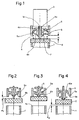
- the shut-off body 2 is placed on the edge of a line 1 with the aid of a helical spring 4 pressed, which generates the closing force and on an annular hub of a stop ring 5 supports.
- the hub also simultaneously forms a blocking body 5a for the friction brake 6.
- the upper stop flange 6a of the friction brake 6 is in the closed position of the shut-off body 2 pressed against the locking body 5a due to the closing force of the spring 4.
- the thread reel-like Friction brake 6 consists of thermoplastic homopolymers, in particular polyoxymethylene (POM) and is at the lower end by means of a clamping ring 7 on the shaft 3c of the shut-off body 2 clamped, which connects the latter with an anchor 3, the drive body is electromagnetically effective.
- the shaft 3c is surrounded by a coating, which is the friction surface 3a for the inner lateral surface of the friction brake 6 as described below.
- the Shut-off body 2 made of a rubber-elastic part, e.g. Katschuk materials such as nitrile rubber (NBR), is around the stroke house of the closed position (Figure 1) in the fully open position ( Figure 3) movable by means of the armature 3 against the force of the spring 4. Strikes in the closed position the shut-off body 2 on the lower edge of the stop ring 5 serving as stop 5b for this on.
- NBR nitrile rubber
- the friction brake 6 comes into operation when the shut-off body 2 is only a friction distance R1 far from the stop 5b. At this moment, the lower stop flange 6b lies against the annular hub, which serves as a locking body 5a. If the friction brake 5 were immovably connected to the shaft 3c, the shut-off body 2 could not reach its locked position. In order to make this possible, the force of the drive body 3 presses the locking body from the position of FIG. 2 into the locking position of FIG. 3. The friction brake 6 rubs along the friction surface 3a, as a result of which the stop forces of the shut-off body 2 at the stop 5b are significantly reduced .
- the drive force serves to overcome the additional frictional force of the friction brake. As a result, it brakes the opening movements at the end of the movement path and ensures a damped Impact "of the shut-off body on the stop.
- the spring 4 presses the shut-off body 2 from the position in FIG. 3 via the position in FIG. 4 back into the closed position in FIG. 1. Also on this movement path along the stroke H is shortly before the stop is reached 1a through the shut-off body 2 in turn a friction distance R2, in which the friction brake 6 operates again, this time in the opposite direction, when its upper stop flange 6a has reached the locking body 5a.
- the spring force of the spring 4 is due to the kinetic energy of the armature built "force is superimposed, the frictional force of the friction brake opposes these forces and thereby dampens the impact on the valve seat.
- the closing process can be divided into three phases, namely in a first phase and a third phase in which the friction brake is not active while the Friction brake comes into operation in an intermediate phase.
- the annular friction brake 6 is in the space between the main part of the cylindrical drive body 3 and one over the shaft 3c with this connected also cylindrical secondary part 3b on the end face.
- the one facing down Surface of the secondary part 3b serves as a locking body 3e as well as the upper end face of the main part of the Drive body 3 serves as a blocking body 3d for the friction brake 6 when this along the Friction surface 8a from the position shown in FIG. 5 via FIG. 6 to the position shown in FIG. 7 and from this back over the position of Figure 8 in the closed position of the shut-off body of Figure 5 is moved.
- the friction or friction occurs between the cylindrical Outer wall of the friction brake 6 and the cylindrical inner wall serving as the friction surface 8a of the housing 8.
- the distance of the blocking bodies 3d and 3e and the thickness of the annular Friction brake 6 determine the point in time at which it starts its closing or opening movement inhibitory or braking function begins.
Landscapes
- Engineering & Computer Science (AREA)
- General Engineering & Computer Science (AREA)
- Mechanical Engineering (AREA)
- Braking Arrangements (AREA)
- Magnetically Actuated Valves (AREA)
- Valves And Accessory Devices For Braking Systems (AREA)
- Details Of Valves (AREA)
- Dowels (AREA)
- Fittings On The Vehicle Exterior For Carrying Loads, And Devices For Holding Or Mounting Articles (AREA)
- Valve Device For Special Equipments (AREA)
Abstract

Description

- Figur 1
- einen schematischen Querschnitt durch ein als Absperrventil ausgebildetes Absperrorgan in der geschlossenen Stellung;
- Figur 2,3 und 4
- entsprechende vereinfachte Schaubilder in anderen Stellungen bzw. Positionen des Absperrkörpers;
- Figur 5
- eine der Figur 1 entsprechende schematische Darstellung einer anderen Ausbildung der Erfindung gleichfalls in der geschlossenen Stellung und
- Figur 6,7 und 8
- andere Stellungen bzw. Positionen als der von Figur 5 des betreffenden Absperrkörpers.
Claims (11)
- Absperrorgan mit einem Absperrkörper (2), der von einem Antrieb zwischen Anschlägen (1a, 5b) bewegbar ist, dadurch gekennzeichnet, daß eine Reibungsbremse (6) mit dem Absperrkörper (2) zwischen Sperrkörpern (5a; 3d, 3e) bewegbar ist, an denen die Reibungsbremse (6) jeweils eine Reibungsstrecke (R1, R2) weit vor dem Zeitpunkt anlangt, an dem der Absperrkörper (2) seinen betreffenden Anschlag (1a, 5b) erreicht, und daß die Reibungsbremse (6) beim Bewegen des Absperrkörpers (2) entlang der Reibungsstrecke (R1, R2) an einer Reibungsfläche (3a; 8a) entlangreibt.
- Absperrorgan nach Anspruch 1, dadurch gekennzeichnet, daß der Sperrkörper (5a) mit dem Anschlag (5b) für den Absperrkörper (2) in dessen geöffneter Stellung verbunden ist.
- Absperrorgan nach Anspruch 1, dadurch gekennzeichnet, daß der Sperrkörper (3, 3b) mit dem Absperrkörper (2) verbunden ist.
- Absperrorgan nach einem der vorhergehenden Ansprüche, dadurch gekennzeichnet, daß die Reibungsfläche (3a) vom Schaft (3c) des Absperrkörpers (2) bzw. von einem den Schaft (3c) umgebenden Überzug gebildet ist, der diesen mit dem Antrieb verbindet.
- Absperrorgan nach einem der vorhergehenden Ansprüche, dadurch gekennzeichnet, daß die Reibungsfläche (8a) von der Innenwand eines Gehäuses (8) gebildet ist, in der ein Antriebskörper (3) des Antriebs entlangbewegbar ist.
- Absperrorgan nach einem der vorhergehenden Ansprüche, dadurch gekennzeichnet, daß die Reibungsbremse (6) als Ring ausgebildet ist.
- Absperrorgan nach einem der vorhergehenden Ansprüche, dadurch gekennzeichnet, daß die Reibungsbremse (6) zwei Anschlagflansche (6a, 6b) aufweist.
- Absperrorgan nach einem der vorhergehenden Ansprüche, dadurch gekennzeichnet, daß die Reibungsbremse (3) aus thermoplastischen Hornopolymerisaten, insbesondere Polyoxymethylen (POM) besteht.
- Absperrorgan nach einem der vorhergehenden Ansprüche, dadurch gekennzeichnet, daß der Antrieb einen elektromagnetisch wirksamen Anker als Antriebskörper (3) aufweist.
- Absperrorgan nach einem der vorhergehenden Ansprüche, dadurch gekennzeichnet, daß dem Antriebskörper (3) eine Feder (4) entgegenwirkt.
- Absperrorgan nach einem der vorhergehenden Ansprüche, dadurch gekennzeichnet, daß der Absperrkörper (2) als gummielastischer Ventilteller eines Absperrventils ausgebildet ist.
Applications Claiming Priority (2)
| Application Number | Priority Date | Filing Date | Title |
|---|---|---|---|
| DE19937627A DE19937627A1 (de) | 1999-08-10 | 1999-08-10 | Absperrorgan |
| DE19937627 | 1999-08-10 |
Publications (3)
| Publication Number | Publication Date |
|---|---|
| EP1076195A2 true EP1076195A2 (de) | 2001-02-14 |
| EP1076195A3 EP1076195A3 (de) | 2002-09-04 |
| EP1076195B1 EP1076195B1 (de) | 2006-02-01 |
Family
ID=7917782
Family Applications (1)
| Application Number | Title | Priority Date | Filing Date |
|---|---|---|---|
| EP00112839A Expired - Lifetime EP1076195B1 (de) | 1999-08-10 | 2000-06-17 | Absperrorgan |
Country Status (8)
| Country | Link |
|---|---|
| US (1) | US6318702B1 (de) |
| EP (1) | EP1076195B1 (de) |
| JP (1) | JP2001065735A (de) |
| CN (1) | CN1182335C (de) |
| AT (1) | ATE317083T1 (de) |
| BR (1) | BR0003455A (de) |
| DE (2) | DE19937627A1 (de) |
| PL (1) | PL192781B1 (de) |
Families Citing this family (5)
| Publication number | Priority date | Publication date | Assignee | Title |
|---|---|---|---|---|
| CN100366965C (zh) * | 2001-07-10 | 2008-02-06 | 日本电产三协株式会社 | 阀驱动设备 |
| US7516941B2 (en) * | 2005-10-11 | 2009-04-14 | Elkhart Brass Manufacturing Company, Inc. | Valve with actuation sub-assembly |
| US20080197311A1 (en) * | 2007-02-12 | 2008-08-21 | Elkhart Brass Manufacturing Company, Inc. | Adjustable mechanical device for controlling valve closure speed |
| JP5573702B2 (ja) * | 2011-01-26 | 2014-08-20 | トヨタ自動車株式会社 | 電磁式リニア弁 |
| US9677679B2 (en) * | 2013-06-26 | 2017-06-13 | Dresser, Inc. | Valve with force generating element |
Family Cites Families (14)
| Publication number | Priority date | Publication date | Assignee | Title |
|---|---|---|---|---|
| DE131780C (de) | ||||
| DE1136175B (de) * | 1960-10-13 | 1962-09-06 | Georg Weisheit | Ventil mit elektromotorischem Antrieb und Daempfungseinrichtung |
| AT274501B (de) * | 1966-12-13 | 1969-09-25 | Kromschroeder Ag G | Elektromagnetisch betätigtes Ventil |
| DE1299966B (de) * | 1967-06-28 | 1969-07-24 | Thomas Fa Robert | Regelventil mit Magnetantrieb und Daempfungseinrichtung |
| DE1614744C3 (de) * | 1967-12-07 | 1974-05-09 | Runtal Holding Co., S.A., Neuenburg (Schweiz) | Wechselstrom- Elektromagnet in geschlossenem Gehäuse mit einstellbarer Bewegungsverzögerung |
| DE6610392U (de) * | 1967-12-07 | 1973-11-29 | Runtal Holding Co Sa | Elektromagnet-system als steuervorrichtung fuer ventile. |
| DD131780A1 (de) * | 1977-04-25 | 1978-07-19 | Hoffmann Ulf Rainer | Bremseinrichtung fuer federrueckstellende ventile |
| DE3210768C2 (de) * | 1982-03-24 | 1990-07-12 | Bopp & Reuther Gmbh, 6800 Mannheim | Sicherheitsventil mit einer Reibeinrichtung zum Unterdrücken von Ventilschwingungen |
| US4890641A (en) * | 1988-12-06 | 1990-01-02 | Teledyne Inc., Teledyne Farris Eng. Div. | Frictional damper suitable for pressure relief valves |
| US5039060A (en) * | 1990-02-01 | 1991-08-13 | Westinghouse Electric Corp. | Control valve vibration damper/isolator |
| DE4332117B4 (de) * | 1993-09-22 | 2005-05-04 | Robert Bosch Gmbh | Elektromagnetventil |
| KR100248332B1 (ko) * | 1995-12-23 | 2000-04-01 | 정몽규 | 차량의 흡/배기밸브용 개폐장치 |
| DE29703584U1 (de) * | 1997-02-28 | 1998-06-25 | FEV Motorentechnik GmbH & Co. KG, 52078 Aachen | Elektromagnetischer Aktuator mit Fluid-Auftreffdämpfung |
| DE19743081A1 (de) * | 1997-09-30 | 1999-04-01 | Bayerische Motoren Werke Ag | Elektromagnetischer Aktuator zur Steuerung eines Hubventils, insbesondere Gaswechselventil einer Brennkraftmaschine |
-
1999
- 1999-08-10 DE DE19937627A patent/DE19937627A1/de not_active Withdrawn
-
2000
- 2000-06-17 AT AT00112839T patent/ATE317083T1/de not_active IP Right Cessation
- 2000-06-17 DE DE50012145T patent/DE50012145D1/de not_active Expired - Fee Related
- 2000-06-17 EP EP00112839A patent/EP1076195B1/de not_active Expired - Lifetime
- 2000-07-10 US US09/612,871 patent/US6318702B1/en not_active Expired - Fee Related
- 2000-07-26 JP JP2000224703A patent/JP2001065735A/ja active Pending
- 2000-07-31 CN CNB001222260A patent/CN1182335C/zh not_active Expired - Fee Related
- 2000-08-02 PL PL341807A patent/PL192781B1/pl not_active IP Right Cessation
- 2000-08-09 BR BR0003455-0A patent/BR0003455A/pt not_active Application Discontinuation
Also Published As
| Publication number | Publication date |
|---|---|
| ATE317083T1 (de) | 2006-02-15 |
| BR0003455A (pt) | 2001-06-12 |
| DE19937627A1 (de) | 2001-02-15 |
| PL192781B1 (pl) | 2006-12-29 |
| US6318702B1 (en) | 2001-11-20 |
| EP1076195A3 (de) | 2002-09-04 |
| JP2001065735A (ja) | 2001-03-16 |
| PL341807A1 (en) | 2001-02-12 |
| CN1287236A (zh) | 2001-03-14 |
| EP1076195B1 (de) | 2006-02-01 |
| CN1182335C (zh) | 2004-12-29 |
| DE50012145D1 (de) | 2006-04-13 |
Similar Documents
| Publication | Publication Date | Title |
|---|---|---|
| EP0484648B1 (de) | Anschlag mit einer Dämpfungseinrichtung | |
| EP2017421B1 (de) | Dämpfvorrichtung für bewegbare Möbelteile | |
| DE1272666B (de) | Elektromagnetisch betaetigbares Ventil mit Tauchankermagnetsystem | |
| DE20107426U1 (de) | Bremsregler mit Luft- oder Flüssigkeitsdämpfung, insbesondere zur Endlagendämpfung von Schubladen, Türen o.dgl. Einrichtungen | |
| WO1996026343A1 (de) | Türschliesser | |
| EP3440376A1 (de) | Verstellbare dämpfventileinrichtung für einen schwingungsdämpfer | |
| DE19907732A1 (de) | Proportionalmagnet mit abziehbarer Spule | |
| DE29703584U1 (de) | Elektromagnetischer Aktuator mit Fluid-Auftreffdämpfung | |
| EP0217039B1 (de) | Abdichtungseinrichtung an einer Kolben-Zylinderanordnung, insbesondere zur Abdichtung des Ventilkegels an Ventilen mit Druckausgleich | |
| DE3831554C2 (de) | Drosselrückschlagventil | |
| DE60108898T2 (de) | Elektromagnetisches zweiwegeventil | |
| DE2445377A1 (de) | Vorrichtung zum einstellen der daempfkraft eines stossdaempfers | |
| EP0666809B1 (de) | Hydraulisches druckminderventil | |
| DE3939537B4 (de) | Magnetventil | |
| AT395053B (de) | Sanitaerarmatur | |
| EP0242349B1 (de) | Verfahren zum Anpassen eines Verdichterventils an unterschiedliche Betriebsverhaeltnisse des Verdichters und Verdichterventil zur Durchfuehrung des Verfahrens | |
| EP1076195B1 (de) | Absperrorgan | |
| DE19712895C2 (de) | Schwingungsdämpfer mit richtungsabhängigem Voröffnungsquerschnitt | |
| DE3001538C2 (de) | Entlüftungsvorrichtung für ein Ventil | |
| DE102004057573B4 (de) | Elektromagnetisch ansteuerbares Wegeventil | |
| DE102007059054A1 (de) | Elektromagnetische Stellvorrichtung | |
| DE8707936U1 (de) | Dämpfungsvorrichtung, insbesondere für Betätigungsteile in Kraftfahrzeugen | |
| WO2020114560A1 (de) | Ventil und vorrichtung zur regelung von drücken eines strömungsmittels in einem fahrzeuggetriebe mit einem ventil | |
| EP3207241A1 (de) | Kraftstoffeinspritzventil | |
| EP1837567B1 (de) | Sicherheitsventil zum automatischen Absperren von Gasleitungen |
Legal Events
| Date | Code | Title | Description |
|---|---|---|---|
| PUAI | Public reference made under article 153(3) epc to a published international application that has entered the european phase |
Free format text: ORIGINAL CODE: 0009012 |
|
| AK | Designated contracting states |
Kind code of ref document: A2 Designated state(s): AT BE CH CY DE DK ES FI FR GB GR IE IT LI LU MC NL PT SE |
|
| AX | Request for extension of the european patent |
Free format text: AL;LT;LV;MK;RO;SI |
|
| PUAL | Search report despatched |
Free format text: ORIGINAL CODE: 0009013 |
|
| AK | Designated contracting states |
Kind code of ref document: A3 Designated state(s): AT BE CH CY DE DK ES FI FR GB GR IE IT LI LU MC NL PT SE |
|
| AX | Request for extension of the european patent |
Free format text: AL;LT;LV;MK;RO;SI |
|
| 17P | Request for examination filed |
Effective date: 20030303 |
|
| AKX | Designation fees paid |
Designated state(s): AT BE CH CY DE DK ES FI FR GB GR IE IT LI LU MC NL PT SE |
|
| GRAP | Despatch of communication of intention to grant a patent |
Free format text: ORIGINAL CODE: EPIDOSNIGR1 |
|
| RAP1 | Party data changed (applicant data changed or rights of an application transferred) |
Owner name: SIEMENS SCHWEIZ AG |
|
| GRAS | Grant fee paid |
Free format text: ORIGINAL CODE: EPIDOSNIGR3 |
|
| GRAA | (expected) grant |
Free format text: ORIGINAL CODE: 0009210 |
|
| AK | Designated contracting states |
Kind code of ref document: B1 Designated state(s): AT BE CH CY DE DK ES FI FR GB GR IE IT LI LU MC NL PT SE |
|
| PG25 | Lapsed in a contracting state [announced via postgrant information from national office to epo] |
Ref country code: IE Free format text: LAPSE BECAUSE OF FAILURE TO SUBMIT A TRANSLATION OF THE DESCRIPTION OR TO PAY THE FEE WITHIN THE PRESCRIBED TIME-LIMIT Effective date: 20060201 Ref country code: FI Free format text: LAPSE BECAUSE OF FAILURE TO SUBMIT A TRANSLATION OF THE DESCRIPTION OR TO PAY THE FEE WITHIN THE PRESCRIBED TIME-LIMIT Effective date: 20060201 |
|
| REG | Reference to a national code |
Ref country code: GB Ref legal event code: FG4D Free format text: NOT ENGLISH |
|
| REG | Reference to a national code |
Ref country code: CH Ref legal event code: EP |
|
| REG | Reference to a national code |
Ref country code: IE Ref legal event code: FG4D Free format text: LANGUAGE OF EP DOCUMENT: GERMAN |
|
| REF | Corresponds to: |
Ref document number: 50012145 Country of ref document: DE Date of ref document: 20060413 Kind code of ref document: P |
|
| PG25 | Lapsed in a contracting state [announced via postgrant information from national office to epo] |
Ref country code: DK Free format text: LAPSE BECAUSE OF FAILURE TO SUBMIT A TRANSLATION OF THE DESCRIPTION OR TO PAY THE FEE WITHIN THE PRESCRIBED TIME-LIMIT Effective date: 20060501 Ref country code: SE Free format text: LAPSE BECAUSE OF FAILURE TO SUBMIT A TRANSLATION OF THE DESCRIPTION OR TO PAY THE FEE WITHIN THE PRESCRIBED TIME-LIMIT Effective date: 20060501 |
|
| PG25 | Lapsed in a contracting state [announced via postgrant information from national office to epo] |
Ref country code: ES Free format text: LAPSE BECAUSE OF FAILURE TO SUBMIT A TRANSLATION OF THE DESCRIPTION OR TO PAY THE FEE WITHIN THE PRESCRIBED TIME-LIMIT Effective date: 20060512 |
|
| GBT | Gb: translation of ep patent filed (gb section 77(6)(a)/1977) |
Effective date: 20060427 |
|
| PG25 | Lapsed in a contracting state [announced via postgrant information from national office to epo] |
Ref country code: CH Free format text: LAPSE BECAUSE OF NON-PAYMENT OF DUE FEES Effective date: 20060630 Ref country code: LI Free format text: LAPSE BECAUSE OF NON-PAYMENT OF DUE FEES Effective date: 20060630 Ref country code: BE Free format text: LAPSE BECAUSE OF NON-PAYMENT OF DUE FEES Effective date: 20060630 Ref country code: MC Free format text: LAPSE BECAUSE OF NON-PAYMENT OF DUE FEES Effective date: 20060630 |
|
| PG25 | Lapsed in a contracting state [announced via postgrant information from national office to epo] |
Ref country code: PT Free format text: LAPSE BECAUSE OF FAILURE TO SUBMIT A TRANSLATION OF THE DESCRIPTION OR TO PAY THE FEE WITHIN THE PRESCRIBED TIME-LIMIT Effective date: 20060703 |
|
| REG | Reference to a national code |
Ref country code: IE Ref legal event code: FD4D |
|
| ET | Fr: translation filed | ||
| PLBE | No opposition filed within time limit |
Free format text: ORIGINAL CODE: 0009261 |
|
| STAA | Information on the status of an ep patent application or granted ep patent |
Free format text: STATUS: NO OPPOSITION FILED WITHIN TIME LIMIT |
|
| 26N | No opposition filed |
Effective date: 20061103 |
|
| REG | Reference to a national code |
Ref country code: CH Ref legal event code: PL |
|
| PG25 | Lapsed in a contracting state [announced via postgrant information from national office to epo] |
Ref country code: AT Free format text: LAPSE BECAUSE OF NON-PAYMENT OF DUE FEES Effective date: 20060617 |
|
| BERE | Be: lapsed |
Owner name: SIEMENS SCHWEIZ A.G. Effective date: 20060630 |
|
| PG25 | Lapsed in a contracting state [announced via postgrant information from national office to epo] |
Ref country code: GR Free format text: LAPSE BECAUSE OF FAILURE TO SUBMIT A TRANSLATION OF THE DESCRIPTION OR TO PAY THE FEE WITHIN THE PRESCRIBED TIME-LIMIT Effective date: 20060502 |
|
| PG25 | Lapsed in a contracting state [announced via postgrant information from national office to epo] |
Ref country code: LU Free format text: LAPSE BECAUSE OF NON-PAYMENT OF DUE FEES Effective date: 20060617 |
|
| PGFP | Annual fee paid to national office [announced via postgrant information from national office to epo] |
Ref country code: DE Payment date: 20080818 Year of fee payment: 9 |
|
| PG25 | Lapsed in a contracting state [announced via postgrant information from national office to epo] |
Ref country code: CY Free format text: LAPSE BECAUSE OF FAILURE TO SUBMIT A TRANSLATION OF THE DESCRIPTION OR TO PAY THE FEE WITHIN THE PRESCRIBED TIME-LIMIT Effective date: 20060201 |
|
| PGFP | Annual fee paid to national office [announced via postgrant information from national office to epo] |
Ref country code: NL Payment date: 20090612 Year of fee payment: 10 |
|
| PGFP | Annual fee paid to national office [announced via postgrant information from national office to epo] |
Ref country code: FR Payment date: 20090616 Year of fee payment: 10 Ref country code: IT Payment date: 20090624 Year of fee payment: 10 |
|
| PGFP | Annual fee paid to national office [announced via postgrant information from national office to epo] |
Ref country code: GB Payment date: 20090608 Year of fee payment: 10 |
|
| PG25 | Lapsed in a contracting state [announced via postgrant information from national office to epo] |
Ref country code: DE Free format text: LAPSE BECAUSE OF NON-PAYMENT OF DUE FEES Effective date: 20100101 |
|
| REG | Reference to a national code |
Ref country code: NL Ref legal event code: V1 Effective date: 20110101 |
|
| GBPC | Gb: european patent ceased through non-payment of renewal fee |
Effective date: 20100617 |
|
| REG | Reference to a national code |
Ref country code: FR Ref legal event code: ST Effective date: 20110228 |
|
| PG25 | Lapsed in a contracting state [announced via postgrant information from national office to epo] |
Ref country code: IT Free format text: LAPSE BECAUSE OF NON-PAYMENT OF DUE FEES Effective date: 20100617 |
|
| PG25 | Lapsed in a contracting state [announced via postgrant information from national office to epo] |
Ref country code: FR Free format text: LAPSE BECAUSE OF NON-PAYMENT OF DUE FEES Effective date: 20100630 Ref country code: NL Free format text: LAPSE BECAUSE OF NON-PAYMENT OF DUE FEES Effective date: 20110101 |
|
| PG25 | Lapsed in a contracting state [announced via postgrant information from national office to epo] |
Ref country code: GB Free format text: LAPSE BECAUSE OF NON-PAYMENT OF DUE FEES Effective date: 20100617 |