EP1075906A2 - Lösbare Verbindung zwischen Batteriemodulen und elektrischen Geräten - Google Patents
Lösbare Verbindung zwischen Batteriemodulen und elektrischen Geräten Download PDFInfo
- Publication number
- EP1075906A2 EP1075906A2 EP00305905A EP00305905A EP1075906A2 EP 1075906 A2 EP1075906 A2 EP 1075906A2 EP 00305905 A EP00305905 A EP 00305905A EP 00305905 A EP00305905 A EP 00305905A EP 1075906 A2 EP1075906 A2 EP 1075906A2
- Authority
- EP
- European Patent Office
- Prior art keywords
- appliance
- module
- power
- electrical
- interface
- Prior art date
- Legal status (The legal status is an assumption and is not a legal conclusion. Google has not performed a legal analysis and makes no representation as to the accuracy of the status listed.)
- Granted
Links
Images


Classifications
-
- B—PERFORMING OPERATIONS; TRANSPORTING
- B25—HAND TOOLS; PORTABLE POWER-DRIVEN TOOLS; MANIPULATORS
- B25F—COMBINATION OR MULTI-PURPOSE TOOLS NOT OTHERWISE PROVIDED FOR; DETAILS OR COMPONENTS OF PORTABLE POWER-DRIVEN TOOLS NOT PARTICULARLY RELATED TO THE OPERATIONS PERFORMED AND NOT OTHERWISE PROVIDED FOR
- B25F5/00—Details or components of portable power-driven tools not particularly related to the operations performed and not otherwise provided for
- B25F5/02—Construction of casings, bodies or handles
-
- B—PERFORMING OPERATIONS; TRANSPORTING
- B25—HAND TOOLS; PORTABLE POWER-DRIVEN TOOLS; MANIPULATORS
- B25F—COMBINATION OR MULTI-PURPOSE TOOLS NOT OTHERWISE PROVIDED FOR; DETAILS OR COMPONENTS OF PORTABLE POWER-DRIVEN TOOLS NOT PARTICULARLY RELATED TO THE OPERATIONS PERFORMED AND NOT OTHERWISE PROVIDED FOR
- B25F3/00—Associations of tools for different working operations with one portable power-drive means; Adapters therefor
-
- H—ELECTRICITY
- H01—ELECTRIC ELEMENTS
- H01M—PROCESSES OR MEANS, e.g. BATTERIES, FOR THE DIRECT CONVERSION OF CHEMICAL ENERGY INTO ELECTRICAL ENERGY
- H01M50/00—Constructional details or processes of manufacture of the non-active parts of electrochemical cells other than fuel cells, e.g. hybrid cells
- H01M50/20—Mountings; Secondary casings or frames; Racks, modules or packs; Suspension devices; Shock absorbers; Transport or carrying devices; Holders
- H01M50/202—Casings or frames around the primary casing of a single cell or a single battery
-
- H—ELECTRICITY
- H01—ELECTRIC ELEMENTS
- H01M—PROCESSES OR MEANS, e.g. BATTERIES, FOR THE DIRECT CONVERSION OF CHEMICAL ENERGY INTO ELECTRICAL ENERGY
- H01M50/00—Constructional details or processes of manufacture of the non-active parts of electrochemical cells other than fuel cells, e.g. hybrid cells
- H01M50/20—Mountings; Secondary casings or frames; Racks, modules or packs; Suspension devices; Shock absorbers; Transport or carrying devices; Holders
- H01M50/244—Secondary casings; Racks; Suspension devices; Carrying devices; Holders characterised by their mounting method
-
- H—ELECTRICITY
- H01—ELECTRIC ELEMENTS
- H01M—PROCESSES OR MEANS, e.g. BATTERIES, FOR THE DIRECT CONVERSION OF CHEMICAL ENERGY INTO ELECTRICAL ENERGY
- H01M50/00—Constructional details or processes of manufacture of the non-active parts of electrochemical cells other than fuel cells, e.g. hybrid cells
- H01M50/20—Mountings; Secondary casings or frames; Racks, modules or packs; Suspension devices; Shock absorbers; Transport or carrying devices; Holders
- H01M50/247—Mountings; Secondary casings or frames; Racks, modules or packs; Suspension devices; Shock absorbers; Transport or carrying devices; Holders specially adapted for portable devices, e.g. mobile phones, computers, hand tools or pacemakers
-
- H—ELECTRICITY
- H01—ELECTRIC ELEMENTS
- H01M—PROCESSES OR MEANS, e.g. BATTERIES, FOR THE DIRECT CONVERSION OF CHEMICAL ENERGY INTO ELECTRICAL ENERGY
- H01M50/00—Constructional details or processes of manufacture of the non-active parts of electrochemical cells other than fuel cells, e.g. hybrid cells
- H01M50/20—Mountings; Secondary casings or frames; Racks, modules or packs; Suspension devices; Shock absorbers; Transport or carrying devices; Holders
- H01M50/296—Mountings; Secondary casings or frames; Racks, modules or packs; Suspension devices; Shock absorbers; Transport or carrying devices; Holders characterised by terminals of battery packs
-
- Y—GENERAL TAGGING OF NEW TECHNOLOGICAL DEVELOPMENTS; GENERAL TAGGING OF CROSS-SECTIONAL TECHNOLOGIES SPANNING OVER SEVERAL SECTIONS OF THE IPC; TECHNICAL SUBJECTS COVERED BY FORMER USPC CROSS-REFERENCE ART COLLECTIONS [XRACs] AND DIGESTS
- Y02—TECHNOLOGIES OR APPLICATIONS FOR MITIGATION OR ADAPTATION AGAINST CLIMATE CHANGE
- Y02E—REDUCTION OF GREENHOUSE GAS [GHG] EMISSIONS, RELATED TO ENERGY GENERATION, TRANSMISSION OR DISTRIBUTION
- Y02E60/00—Enabling technologies; Technologies with a potential or indirect contribution to GHG emissions mitigation
- Y02E60/10—Energy storage using batteries
Definitions
- This invention relates generally to portable electrical power tools, and specifically to interfaces for releasably connecting power control modules to electrical appliances, and to methods of connecting such interfaces.
- the design of the interface between common and specific modules is critical to the safety and reliability of such a modular system. When transferring electrical power or signals across such an interface, care should be taken to ensure reliable electrical contact. In addition, the modules should lock together in a manner which avoids inadvertent separation.
- Modular cordless systems in which a common module contains a storage battery and task-specific modules contain electric motors, require electrical power to be transferred across the module interface. It is important in many applications that motors of such tools not be inadvertently energized during assembly and disassembly of the common module, or battery pack, with any given task-specific module, or tool chassis.
- the invention features an improved interface for releasably connecting an electrical appliance and a power control module having a power control trigger and being adapted to provide electrical power to a motor of the appliance.
- the interface (which defines an interface plane between the appliance and power control module) includes a flange extending from one of the module and appliance and arranged to be inserted through an aperture in the other of the module and appliance as the module and appliance are moved toward the interface plane in a disengaged position.
- the other of the module and appliance defines a corresponding slot to receive the flange as the module and appliance are subsequently slid across one another along the interface plane to an engaged position.
- the interface also includes a latch extending from one of the module and appliance to engage a detent of the other of the module and appliance, to releasably retain the module and appliance in their engaged position.
- a first electrical contact, attached to one of the module and appliance is arranged to engage a second electrical contact attached to the other of the module and appliance with the module and appliance in their engaged position, to transfer electrical power from the module to the appliance.
- the interface also includes an actuator extending from the power control module and operable by the trigger.
- the actuator is arranged to engage an electrical switch mechanism of the appliance to control a flow of electrical current from the power control module to the appliance.
- the actuator in some instances, is a lever extending from the power control module and adapted to move in a direction along the interface plane to depress the electrical switch mechanism as the trigger is actuated.
- one of the module and appliance also includes a latch release mechanism exposed for manual operation to and adapted to release the latch to enable the module and appliance to be moved to their disengaged position.
- the latch release mechanism is constructed and arranged to physically block operation of the actuator while the latch release mechanism is operated. It is also preferred that the actuator be constructed and arranged to physically block operation of the latch release mechanism while the trigger is actuated.
- the latch release mechanism may include a pair of depressible buttons, which may be connected by a resilient member, disposed on opposite sides of one of the module and appliance, for example.
- the interface is constructed and arranged to allow moving the module and appliance to their engaged position without operating the latch release mechanism.
- the actuator is constructed to engage and retain the latch release mechanism in a non-latched position when the trigger is pulled while the latch release mechanism is in its non-latched position.
- the actuator may define an undercut engageable by a hooked protrusions extending from opposing ears of the latch release mechanism.
- the latch and latch release mechanism are components of the appliance.
- one of the module and appliance has two flanges extending in opposite directions generally parallel to the interface plane and perpendicular to the slot.
- the other of the module and appliance defines two slots, arranged in opposition, for receiving the flanges with the module and appliance in their engaged position.
- the one of the module and appliance having the two flanges also has, in some configurations, an auxiliary flange spaced apart from, and parallel to, the two flanges.
- the other of the module and appliance further defines a third slot, of different dimensions than the other two slots, for receiving the auxiliary flange as the module and appliance are moved to their engaged position.
- the interface is constructed and arranged to permit the flange to be inserted through the aperture with the module and appliance in only one orientation.
- the first and second electrical contacts extend along the interface plane such that the contacts slide across one another as the module and appliance are moved toward their engaged position.
- the interface includes a wide dovetail portion extending from the appliance and arranged to be inserted, through an aperture in the power module, toward the interface plane with the module and appliance in a disengaged position.
- the power module defines a first slot to receive the wide dovetail portion of the appliance as the power module and appliance are subsequently slid across one another along the interface plane to an engaged position.
- the interface also includes an actuator extending from the power control module and operable by the trigger. The actuator is arranged to engage an electrical switch mechanism of the appliance to control a flow of electrical current from the power control module to the appliance.
- the interface includes a latch extending from the appliance to engage a detent of the power module, to releasably retain the module and appliance in their engaged position.
- the latch is operable by a latch release mechanism exposed for manual operation on the appliance.
- the interface also includes an electrical contact attached to the power module and arranged to engage an electrical contact of the appliance with the module and appliance in their engaged position, to transfer electrical power from the module to the appliance.
- the power module also defines a second slot, spaced apart from the first slot along the interface plane and adapted to receive a narrow dovetail portion extending from the appliance, as the module and appliance are slid along the interface plane toward their engaged position.
- the wide dovetail portion is between about 75 and 85 millimeters in width, as measured across the interface plane
- the narrow dovetail portion is between about 55 and 65 millimeters in width, as measured across the interface plane.
- the interface includes flanges on each of the power control module and appliance, a latch pawl, electrical contacts on each of the power control module and appliance, an actuator, and a latch release.
- the flanges are arranged to overlap as the power module is slid along the interface plane, to an engaged position on the appliance.
- the latch pawl extends from the appliance to engage a detent of the power control module, to releasably retain the module in its engaged position.
- the contacts are arranged for electrical engagement when the module is in the engaged position, to transfer electrical power from the module to the appliance, and the actuator extends from the power control module to activate an electrical switch of the appliance when a trigger of the power control module is actuated.
- the latch release mechanism is exposed for manual operation to retract the latch pawl and physically block activation of the electrical switch by the actuator during power control module installation and removal.
- a power control module for providing power to a portable electrical appliance, includes a housing having a mounting face configured for releasable attachment to a corresponding face of the electrical appliance.
- the mounting face defines an aperture for receiving a flange of the appliance face as the housing and appliance faces are moved toward one another in a disengaged position, and a slot contiguous with and extending from the aperture along the mounting face, for receiving the flange of the appliance face as the housing and appliance faces are slid across one another to an engaged position.
- An electrical contact of the power control module extends from the housing and is exposed to engage a mating contact of the appliance as the housing and appliance are moved to their engaged position. The contact is adapted to transfer electrical power from the power control module to the appliance.
- a trigger is movably attached to the housing and exposed to be manipulated by an operator to control the appliance.
- the power control module also includes a battery contained within the housing (which may define a graspable handle, for instance) and electrically connected to the electrical contact.
- the power control module is adapted to receive electrical power from an external power source while attached to the appliance.
- the power control module may include, for instance, an electrical cord for plugging the module into an AC electrical outlet.
- the power control module has an external contact for connection to an external DC power source.
- Various embodiments of the power control module have one or more of the features discussed above with respect to the interface of the invention.
- a portable electrical appliance is configured to accept, in a releasable attachment, the above-described power control module.
- the portable electrical appliance adapted to be powered by the removable power module, includes an electrical motor arranged to do useful work and has a power module mounting face with two sets of outwardly extending flanges and an electrical contact for receiving electrical power from the power module for driving the motor.
- the two sets of flanges are spaced apart, in a direction parallel to the slots, for receiving a mating set of flanges of the power module between them in a first assembly motion.
- the two sets of flanges overhang associated slots adapted to receive mating flanges of the power module during a second assembly motion, generally perpendicular to the first assembly motion, to retain the power module on the appliance.
- one set of the flanges extends over a greater width, measured in a direction perpendicular to the slots, than the other set of flanges.
- the wider set of flanges extends over a width of about 82 millimeters.
- the appliance also includes, in some instances, a latch extending outwardly into one of the overhung slots and adapted to engage a detent of the power module to releasably retain the module and appliance in an engaged position.
- an improved portable electrical power tool includes an appliance and a removable power module.
- the appliance has an electrical motor arranged to do useful work, and a housing with a mounting face having an extending flange and an electrical contact for receiving electrical power.
- the removable power module has a housing with a mounting face configured for releasable attachment to the mounting face of the appliance housing.
- the mounting face of the power module housing defines an aperture for receiving the flange of the appliance mounting face as the mounting faces are moved toward one another in a disengaged position.
- the mounting face of the power module also defines a slot, contiguous with and extending from the aperture along the power module mounting face, for receiving the flange of the appliance mounting face as the mounting faces are slid across one another to an engaged position.
- the power module also includes an electrical contact and a trigger.
- the electrical contact extends from the power module housing and is exposed to engage the contact of the appliance as the power module is moved to its engaged position.
- the contact is adapted to transfer electrical power from the power control module to the appliance.
- the trigger is movably attached to the power module housing and is exposed to be manipulated by an operator to control the appliance.
- the removable power module is a battery pack containing at least one electrical storage battery.
- the battery may be adapted to be recharged through the electrical contact extending from the power module housing, and may be adapted to be recharged within the battery pack while the battery pack is installed on the appliance.
- the power tool is an outdoor home gardening tool, such as a trimmer, blower, cultivator, pruning saw, hedge trimmer or the like.
- the power tool may also be a woodworking tool, such as a circular saw or sander, or other useful device, such as a light or a vacuum-cleaner, for example.
- a method of releasably installing a removable power control module on an electrical appliance includes the steps of
- the invention can provide a safe, reliable interface between power-providing and power-consuming modules of a power tool system. Undesirable power transfer during assembly and disassembly can be avoided, and the two-motion procedure required to expose the contacts and separate the interface can help to protect from accidental release as well as requiring a desirably small amount of overall travel for engagement.
- a comfortable weight distribution can be established.
- the switch may be efficiently matched to the power requirements of the associated motor and be selected to provide a mode of control appropriate for the given tool.
- Fig. 1 is a perspective view of a power trimmer.
- Figs. 2A-2C sequentially illustrate the installation of the battery pack onto the trimmer of Fig. 1.
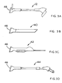
- Figs. 3A-3D illustrate other power tools adapted to be powered by the power pack of Fig. 2.
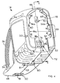
- Fig. 4 is a perspective view of the power pack, showing its mounting face.
- Fig. 5 is a cross-sectional view, taken along line 5-5 of Fig. 4.
- Fig. 6 is a perspective view of the battery pack mounting face of the trimmer chassis.
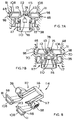
- Figs. 7A and 7B illustrate the latch release allowing and inhibiting, respectively, operation of the trigger switch.
- Fig. 8 is a perspective view of a one-piece latch release.
- Fig. 9 shows the battery pack being mounted to a recharging station.
- Fig. 10 is a side view of a corded electrical power module.
- power string trimmer 10 consists of a motorized chassis 12 and a removable battery pack 14.
- Chassis 12 includes a head 16 with an internal electric motor (not shown) arranged to drive a partially shielded rotary string hub 18 with an extending string element 19 for cutting weeds and grasses.
- Head 16 is connected to an upper chassis housing 20 by a tube 22 through which wires conduct electrical power from battery pack 14 to the motor of head 16.
- the trimmer is held by both hands in use, with a forward stirrup grip 24 and a rear handle 26 on the battery pack.
- a forefinger-operable trigger 28 in handle 26 controls the flow of power from the battery pack to the trimmer motor, and a trigger lock 30 automatically locks the trigger in its "off" position until actuated, preventing inadvertent trigger operation.
- battery pack 14 is readily attached to the upper chassis housing 20 of the trimmer in a two-motion sequence.
- the mounting faces of the battery pack 14 and upper chassis housing 20 are brought together in a motion perpendicular to the faces (indicated by arrow "A") with the alignment indicator 32 of the battery pack housing aligned with an "unlocked" indicator 34 of the upper chassis housing.
- the battery pack 14 and upper chassis housing 20 are positioned as shown in Fig. 2B.
- the battery pack and upper chassis housing mounting faces are slid across one another along their interface plane 35, as indicated by arrows "B" in Fig.
- Indicators 32, 34 and 36 are integrally molded as features of the plastic housings of the battery pack and upper chassis, and feature appropriate icons.
- Figs. 2A-2C To remove battery pack 14 from upper chassis housing 20, the sequence of Figs. 2A-2C is reversed. First, the user depresses a pair of latch release buttons 38 located on either side of the upper chassis housing (only one is shown in these views). Depressing the latch release buttons releases a battery pack mounting latch (not shown) and enables the user to slide the two mounting faces across each other to the position shown in Fig. 2B, where they may be separated perpendicularly as shown in Fig. 2A. With the battery pack mounted as shown in Fig. 2C, the internal configuration of the trigger mechanism and the mounting latch, as discussed in more detail below, disallows depressing latch release buttons 38 while trigger 28 is pulled, and disallows pulling the trigger while the latch release buttons are depressed.
- the trigger and latch cooperate to prevent contact arcing and inadvertent energizing of the trimmer motor during battery pack mounting and detachment, as well as accidental unlatching of the battery pack 14 from the chassis 12 (Fig. 1) while the power consuming device is operating.
- Cordless battery pack 14 may be employed to power a large variety of power tools and equipment.
- Figs. 3A-3D illustrate, in order, string trimmer chassis 12, a leaf blower 40, a long reach hedge trimmer 42, and a pruning saw 44.
- Each tool is provided with a similar battery pack mounting face 46 adapted to receive the battery pack.
- Other portable cordless electrical tools such as hand-held vacuum cleaners, paint sprayers, cultivators, rotating brushes, high-power flashlights and the like, are also envisioned.
- one or two battery packs may be employed to sequentially operate an entire suite of tools and appliances.
- battery pack 14 has left and right housing halves 48 and 50 of injection molded ABS plastic, joined along line 52 and held together by a series of threaded fasteners accessed through sockets 54. Together, housing halves 48 and 50 form a generally flat mounting face (the near end of the battery pack, as shown in Fig. 4) for securing the battery pack to any one of the tools discussed above. At the mounting face, the housing halves form two sets of opposed, inwardly facing flanges 56a and 56b, and 58a and 58b, which define undercuts for receiving outwardly facing flanges of the mounting face of the mating tool.
- Adjacent flanges 56a and 56b Adjacent flanges 56a and 56b, the extensions of the two housing halves are spaced apart to define a wide aperture 59 of width "W a " of about 84 millimeters (mm), with the inner edges of flanges 56a and 56b separated by only about 72 mm. Slots 60 beneath flanges 56a and 56b receive cooperating flanges of the mating tool, which are first inserted through aperture 59 during the motion illustrated in Fig. 2A.
- overhanging chamfers 61 at the lower edge of aperture 59 catch the mating tool flanges when the two mounting faces are slid apart beyond the aligned position shown in Fig. 2B.
- the tool housing must be first moved slightly back toward its locked position to align the tool flanges with aperture 59 and completely separate the battery pack from the tool.
- Flanges 58a and 58b are separated by only about 50 mm, and overhang slots 62 which receive a corresponding set of outwardly facing flanges of the mating tool.
- the difference in separation widths between the two sets of opposing flanges helps to key the battery pack mounting to disallow mounting in all but the intended orientation.
- a molded wall 64 provides, together with the curvature of the upper end 66 of the mounting face, a firm stop for the motion illustrated in Fig. 2B.
- all of the mounting flanges are molded with double wall construction for rigidity and strength.
- the inner walls of flanges 56a and 56b are relieved to form covered pockets 68 for receiving the pawls of the mounting latch discussed below.
- switch actuator 78 which, with the battery pack mounted, is arranged to operate a power switch of the tool (not shown) when moved parallel to the mounting face by depressing battery pack trigger 28 (Fig. 1).
- a charging port 80 in the underside of the battery pack accepts a direct current (DC) power plug for recharging the battery when not in use, and blind pockets 81 molded into the underside of the housing are for locating the battery pack on an optional charging saddle or for hanging the battery pack against a vertical surface.
- DC direct current
- switch actuator 78 and trigger 28 are portions of a single, unitarily molded acetal polymer lever 80 which is rotatably secured to the battery pack housing at a pivot 82.
- the trigger linkage "reaches through” the interface plane, into the tool, to operate a switch located within the tool.
- This enables the switch itself to be sized appropriately for the power requirements of the tool motor, which may vary between different tools.
- actuator 78 is moved downward, in the direction of arrow "D", and an integrally molded finger 83 extending rearward from trigger 28 is deflected against a protrusion of the housing.
- a projection 84 extends from the upper surface of trigger 28 to interact with trigger lock 30, which is biased rearward by a molded cantilever finger 85 of lock 30 which is deflected against a fixed housing projection with lock 30 in a forward, trigger-releasing position as shown.
- the spring force of cantilever finger 85 moves the lock rearward (in the direction of arrow "E"), where the underside of the lock interferes with projection 84 and prevents pulling of the trigger until lock 30 is again released by holding the lock forward while pulling trigger 28.
- battery 86 Enclosed within the battery pack housing is a storage battery 86 with sufficient capacity to operate any of the associated tools over an extended period of time.
- battery 86 is of the sealed lead acid (SLA) type, but nickel-cadmium (NiCAD), nickel-metal hydride (NiMH) or any other type of rechargeable battery may be employed.
- battery 86 has an operative capacity of at least about 5 amp-hours.
- Battery 86 in this embodiment, operates at a nominal DC voltage of about 12 volts and a normal operating current for powering the string trimmer is about 8 to 12 amps continuous.
- the mounting face of the upper tool housing 20 of the trimmer chassis has both wide and narrow dovetail portions 88 and 90 that mate with the flanges of the mounting face of the battery pack housing.
- Wide dovetail portion 88 has outwardly extending flanges 92a and 92b that extend over a width "W b " of about 82 mm and defines a channel 94 for receiving the switch actuator of the battery pack.
- a switch (not shown) in the base of the channel opens and closes an electrical circuit through the tool motor (also not shown).
- Flanges 92a and 92b overhang slots 96 along the sides of the wide dovetail portion into each of which a moveable latch pawl 98 extends.
- Narrow dovetail portion 90 has outwardly extending flanges 100a and 100b that extend over an overall width of about 48 mm and overhang slots 102 along the sides of the narrow dovetail portion.
- narrow dovetail portion 90 Enclosed within narrow dovetail portion 90 are a pair of electrical contacts 104 in electrical communication with the tool motor (not shown) through the tool power switch (also not shown).
- Contacts 104 similar in construction to contacts 72 of the battery pack (Fig. 4) are mounted to a terminal board 74 with a central rib 76.
- the outer surfaces of contacts 104 (and contacts 72 of Fig. 4) are all sloped with respect to the interface plane between the battery pack and tool housings. During engagement, the contacts are arranged to slide over one another, helping to wipe excess oxidation and other non-conductive material from their contact surfaces.
- the sloped design also helps to ensure that electrical contact is made only along a very narrow band (so-called "line contact”) at the outer portions of the contacts.
- the wide and narrow dovetail portions of the mounting face of the trimmer housing are also provided with tapered ribs 106 on both inner and outer faces of flanges 92a, 92b, 100a and 100b. Ribs 106 help to minimize tolerance play between the battery pack and chassis housings, and also reduce sliding friction by ensuring sliding contact only along the narrow tops of the ribs. Thus, the dovetail joint provides a tight, secure fit with minimal engagement/disengagement effort.
- Figs. 7A and 7B illustrate the interaction of the latch release of the tool and the switch actuator of the battery pack.
- the two ears 108 of the latch release come together between actuator 78 and power switch 110 (i.e., into channel 94 of Fig. 6) to prevent the actuator from depressing the plunger 112 at the top of the switch.
- forward chamfers 111 on pawls 98 help to automatically retract ears 108 as the battery pack is slid to its engaged position, without the user having to depress the latch release buttons.
- the battery pack is in its mounted position (as in Fig.
- the latching pawls 98 at the outer ends of latch release ears 108 snap into the latch pockets 68 of the battery pack housing (Fig. 7A), with ears 108 sufficiently separated to allow passage of actuator 78.
- the actuator blocks the inward movement of ears 108 and prevents the user from releasing the latch.
- hooked protrusions 113 engage a corresponding undercut 115 of actuator 78 to prevent the latch ears from separating and exposing switch 110 until the trigger is released.
- Switch 110 in the string trimmer embodiment is a non-latching, push-on, release-off switch.
- variable-resistance switches are employed to control variable-speed motors, for example. By locating the switch on the interchangeable tool chassis instead of on the battery pack, various switch types may be employed for different tools, as desired.
- latch release 114 is a unitarily molded, plastic member with two pair of parallel beam flexure members 117 extending from a rear cross-member 116 to act as flexure springs to bias ears 108 and buttons 38 of the latch release apart toward an unstressed position.
- the parallel beam arrangement helps to provide a nearly linear motion of ears 108 and buttons 38 during latch release and engagement.
- the flexure of members 117 can be seen, for instance, by comparing Figs. 7A (members straight) and 7B (members flexed).
- Fig. 9 shows a recharging cradle 118 with a mounting face 120 similar to that described above with respect to Fig. 6, but without a latch.
- battery pack 14 When not in use, battery pack 14 is cradled within the charger, engaged against face 120, to recharge its internal battery.
- Cradle 118 includes appropriate transforming and rectifying circuitry to provide a desired DC voltage for charging directly through the contacts 72 (Fig. 4) of the battery pack. Alternating current (AC) power is received through a standard grounded pigtail 122 from a wall outlet (not shown).
- Status lights 124 indicate battery pack charging and mounting status.
- Cradle 118 may be either rested on a table or hung on a vertical wall surface.
- a corded power pack 126 is adapted to power the tools illustrated in Figs. 3A-3D, but has an electrical cord 128 for accepting AC voltage, instead of a DC storage battery. Its housing contains the necessary power conversion circuitry (not shown) for converting 110 volt AC power to DC power of the desired voltage.
Landscapes
- Chemical & Material Sciences (AREA)
- Chemical Kinetics & Catalysis (AREA)
- Electrochemistry (AREA)
- General Chemical & Material Sciences (AREA)
- Engineering & Computer Science (AREA)
- Mechanical Engineering (AREA)
- Life Sciences & Earth Sciences (AREA)
- Biophysics (AREA)
- Computer Hardware Design (AREA)
- Battery Mounting, Suspending (AREA)
- Harvester Elements (AREA)
- Coupling Device And Connection With Printed Circuit (AREA)
Applications Claiming Priority (2)
| Application Number | Priority Date | Filing Date | Title |
|---|---|---|---|
| US353451 | 1999-07-14 | ||
| US09/353,451 US6181032B1 (en) | 1999-07-14 | 1999-07-14 | Releasably connecting power packs to electrical appliances |
Publications (3)
| Publication Number | Publication Date |
|---|---|
| EP1075906A2 true EP1075906A2 (de) | 2001-02-14 |
| EP1075906A3 EP1075906A3 (de) | 2001-04-18 |
| EP1075906B1 EP1075906B1 (de) | 2003-06-25 |
Family
ID=23389159
Family Applications (1)
| Application Number | Title | Priority Date | Filing Date |
|---|---|---|---|
| EP00305905A Expired - Lifetime EP1075906B1 (de) | 1999-07-14 | 2000-07-12 | Lösbare Verbindung zwischen Batteriemodulen und elektrischen Geräten |
Country Status (6)
| Country | Link |
|---|---|
| US (1) | US6181032B1 (de) |
| EP (1) | EP1075906B1 (de) |
| CN (1) | CN1191917C (de) |
| AT (1) | ATE243606T1 (de) |
| AU (1) | AU4722200A (de) |
| DE (1) | DE60003499T2 (de) |
Cited By (25)
| Publication number | Priority date | Publication date | Assignee | Title |
|---|---|---|---|---|
| GB2379090A (en) * | 2001-08-23 | 2003-02-26 | Ta-Chin Wang | Modular base unit for car appliances |
| GB2392002A (en) * | 2002-08-12 | 2004-02-18 | Choon Nang Elec Appl Mfy Ltd | Rechargeable battery pack |
| GB2414704A (en) * | 2004-06-05 | 2005-12-07 | Bosch Gmbh Robert | Electric tool with adjustably positioned handle |
| GB2415656A (en) * | 2004-06-23 | 2006-01-04 | Bosch Gmbh Robert | Hand tool machine with centring means between components |
| WO2006008057A1 (de) * | 2004-07-15 | 2006-01-26 | Marquardt Gmbh | Elektrowerkzeug, insbesondere akku-elektrowerkzeug |
| WO2006045657A1 (de) * | 2004-10-22 | 2006-05-04 | Robert Bosch Gmbh | Elektrohandwerkzeugmaschine mit schalter und angekuppelter elektronik |
| WO2006072490A1 (de) * | 2004-12-29 | 2006-07-13 | Robert Bosch Gmbh | Handwerkzeugmaschine mit einem stabhandgriff |
| EP1788597A1 (de) * | 2005-11-16 | 2007-05-23 | Marquardt GmbH | Elektrowerkzeug, insbesondere Akku-Elektrowerkzeug |
| WO2008122353A2 (de) * | 2007-04-05 | 2008-10-16 | Andreas Stihl Ag & Co Kg | Energiespeichereinheit, arbeitsgerät, ladegerät und arbeitskit für den landschaftsbau |
| EP2008776A1 (de) * | 2007-06-27 | 2008-12-31 | Marquardt GmbH | Elektrowerkzeug, insbesondere Akku-Elektrowerkzeug |
| US7934961B2 (en) | 2008-06-11 | 2011-05-03 | Tyco Electronics Corporation | Low profile contact |
| WO2012002860A1 (en) * | 2010-07-02 | 2012-01-05 | Husqvarna Ab | Battery powered tool |
| EP2223780A3 (de) * | 2009-02-27 | 2012-06-27 | Andreas Stihl AG & Co. KG | Elektroarbeitsgerät mit einem Akkupack |
| CN101528424B (zh) * | 2006-10-05 | 2012-10-31 | 思科实业有限公司 | 模块化电动手用工具 |
| ITRM20110276A1 (it) * | 2011-06-03 | 2012-12-04 | Vilde Nardicchia | Sistema di identificazione di oggetti e di controllo di mezzi di azionamento degli stessi. |
| WO2013117901A1 (en) * | 2012-02-10 | 2013-08-15 | Dyson Technology Limited | Vacuum cleaner and a battery pack therefor |
| WO2013122267A1 (en) * | 2012-02-15 | 2013-08-22 | Hitachi Koki Co., Ltd. | Electric working machine |
| WO2013139793A3 (en) * | 2012-03-19 | 2013-12-19 | Husqvarna Ab | Power adapter for cordless power tools |
| EP3132730A1 (de) * | 2008-10-16 | 2017-02-22 | Royal Appliance Mfg. Co. | Batteriegetriebenes kabelloses reinigungssystem |
| WO2017103095A1 (de) * | 2015-12-16 | 2017-06-22 | Robert Bosch Gmbh | Werkzeugbasismodul |
| EP3348357A1 (de) * | 2016-10-17 | 2018-07-18 | Black & Decker Inc. | Modulares elektrowerkzeug |
| EP3093902B1 (de) * | 2015-05-15 | 2018-12-12 | Black & Decker Inc. | Batteriegehäuseanordnung eines fadenschneiders |
| US10230077B2 (en) | 2012-03-19 | 2019-03-12 | Husqvarna Ab | Carrier system for a backpack energy source, energy source and backpack energy source assembly |
| SE543607C2 (en) * | 2019-03-22 | 2021-04-20 | Husqvarna Ab | Power tool user interface arrangement and power tool with such arrangement |
| EP4011189A1 (de) * | 2020-12-04 | 2022-06-15 | Globe (Jiangsu) Co., Ltd. | Elektrowerkzeugsystem |
Families Citing this family (98)
| Publication number | Priority date | Publication date | Assignee | Title |
|---|---|---|---|---|
| JP3698296B2 (ja) * | 1999-08-19 | 2005-09-21 | 株式会社マキタ | 端子構造 |
| IT248273Y1 (it) * | 1999-08-27 | 2002-12-16 | Eurosystems S P A | Motozappa portatile. |
| US7183745B2 (en) * | 2000-08-11 | 2007-02-27 | Milwaukee Electric Tool Corporation | Adapter for a power tool battery |
| US6525511B2 (en) | 2000-08-11 | 2003-02-25 | Milwaukee Electric Tool Corporation | Adapter for a power tool battery |
| US7443137B2 (en) | 2000-08-11 | 2008-10-28 | Milwaukee Electric Tool Corporation | Adapter for a power tool battery |
| JP3710697B2 (ja) | 2000-09-19 | 2005-10-26 | 株式会社マキタ | 往復動切断工具 |
| US6796478B2 (en) * | 2000-10-12 | 2004-09-28 | Illinois Tool Works Inc. | Fuel cell adapter system for combustion tools |
| JP3853590B2 (ja) * | 2000-12-15 | 2006-12-06 | 株式会社マキタ | 電動工具 |
| US20030201755A1 (en) * | 2002-04-25 | 2003-10-30 | Briggs Scott W. | Battery disable/enable control circuitry of a portable computing device |
| US6898854B2 (en) * | 2002-06-07 | 2005-05-31 | Black & Decker Inc. | Modular power tool |
| US6734379B1 (en) * | 2002-09-06 | 2004-05-11 | Olympia Group, Inc. | Electronic power tool lock-out mechanism |
| US7143835B2 (en) * | 2003-03-17 | 2006-12-05 | Honda Motor Co., Ltd. | Walk-behind electric working machine |
| US6938810B2 (en) | 2003-04-15 | 2005-09-06 | Illinois Tool Works Inc. | Fuel cell adapter system for combustion tools |
| US7121854B2 (en) * | 2003-05-28 | 2006-10-17 | Eastway Fair Company Limited | Slide type battery ejection mechanism |
| US7712182B2 (en) * | 2003-07-25 | 2010-05-11 | Milwaukee Electric Tool Corporation | Air flow-producing device, such as a vacuum cleaner or a blower |
| EP1589550A1 (de) * | 2004-04-20 | 2005-10-26 | GMCA PTY Ltd | Schaltmechanismus |
| US20050244217A1 (en) * | 2004-04-29 | 2005-11-03 | William Burke | Test instrument module latch system and method |
| US7377274B2 (en) * | 2004-05-12 | 2008-05-27 | High Tech High Foundation | Rapid-firing toy gun |
| DE202004020791U1 (de) * | 2004-08-09 | 2006-01-12 | Robert Bosch Gmbh | Akkuschrauber |
| FR2874764B1 (fr) * | 2004-08-31 | 2007-09-21 | Valeo Equip Electr Moteur | Module de commande et de puissance pour une machine electrique tournante |
| US20060179679A1 (en) * | 2004-10-21 | 2006-08-17 | Marley Engineered Products, | Portable multi-purpose blower apparatus and method |
| DE202004018885U1 (de) * | 2004-12-07 | 2006-04-13 | Dolmar Gmbh | Bremse für eine Heckenschere |
| CN2762964Y (zh) * | 2005-01-10 | 2006-03-08 | 南京德朔实业有限公司 | 用电池供电的电动工具 |
| JP4462112B2 (ja) * | 2005-05-26 | 2010-05-12 | パナソニック電工株式会社 | 電動工具 |
| US20070017103A1 (en) * | 2005-07-20 | 2007-01-25 | Black & Decker Inc. | Table mount holder for battery powered scissors |
| DE102006018010A1 (de) * | 2006-04-07 | 2007-10-11 | Robert Bosch Gmbh | Akkupack |
| DE102006018072B4 (de) * | 2006-04-10 | 2016-08-11 | Andreas Stihl Ag & Co. Kg | Heckenschere |
| US20070278326A1 (en) * | 2006-05-30 | 2007-12-06 | Scott Wu | Sprayer with detachable rechargeable battery |
| US20070292749A1 (en) * | 2006-06-15 | 2007-12-20 | Richard Coombs | Battery assembly for vacuums |
| US7913345B2 (en) | 2006-08-15 | 2011-03-29 | Umagination Labs, L.P. | Systems and methods of a power tool system with interchangeable functional attachments |
| US7979945B2 (en) * | 2006-08-15 | 2011-07-19 | Umagination Labs, L.P. | Systems and methods for robotic gutter cleaning |
| US7886399B2 (en) | 2006-08-15 | 2011-02-15 | Umagination Labs, L.P. | Systems and methods for robotic gutter cleaning along an axis of rotation |
| US7743683B2 (en) * | 2006-08-15 | 2010-06-29 | Umagination Labs, L.P. | Systems and methods of a power tool system with interchangeable functional attachments powered by a direct rotational drive |
| US7926141B2 (en) * | 2006-08-15 | 2011-04-19 | Umagination Labs, L.P. | Systems and methods of a gutter cleaning system |
| US9643266B1 (en) * | 2006-10-27 | 2017-05-09 | Battenfeld Technologies, Inc. | Extendable folding saw |
| US7609025B2 (en) * | 2006-11-03 | 2009-10-27 | Snap-On Incorporated | Kit of power tools |
| US9591809B2 (en) * | 2007-02-06 | 2017-03-14 | Mtd Products Inc | Split power tool |
| US8136254B2 (en) * | 2007-02-06 | 2012-03-20 | Mtd Products Inc | Split power tool with extension |
| WO2009006587A1 (en) * | 2007-07-03 | 2009-01-08 | Milwaukee Electric Tool Corporation | Pipe cutter |
| US9486864B2 (en) | 2007-07-03 | 2016-11-08 | Milwaukee Electric Tool Corporation | Pipe cutter |
| US9492941B2 (en) * | 2007-11-08 | 2016-11-15 | Echo, Incorporated | Apparatus having a tool on an elongate pole |
| US20090255084A1 (en) | 2008-03-14 | 2009-10-15 | Gee Ii Jack W | Removable Battery Pack with Latching Mechanism |
| WO2009114867A1 (en) * | 2008-03-14 | 2009-09-17 | Royal Appliance Mfg.Co.D/B/A | Removable battery pack with latching mechanism |
| US8607405B2 (en) | 2008-03-14 | 2013-12-17 | Techtronic Floor Care Technology Limited | Battery powered cordless cleaning system |
| JP5138501B2 (ja) * | 2008-08-11 | 2013-02-06 | 株式会社マキタ | 電池パックが着脱可能な刈払機 |
| JP5130147B2 (ja) * | 2008-08-11 | 2013-01-30 | 株式会社マキタ | 操作棹が汎用性を有する刈払機 |
| JP5825750B2 (ja) * | 2009-03-03 | 2015-12-02 | 日立工機株式会社 | 電動作業機 |
| US7989718B1 (en) * | 2009-05-08 | 2011-08-02 | Weber Eugene A | Power control engagement device for a power tool |
| JP2013520326A (ja) | 2010-02-25 | 2013-06-06 | ディメイン テクノロジー プロプライエタリー リミテッド | 動力工具収納および包装システム |
| JP5653281B2 (ja) * | 2011-04-20 | 2015-01-14 | モレックス インコーポレイテドMolex Incorporated | モジュール用ソケット |
| EP2739439B1 (de) * | 2011-08-01 | 2016-10-05 | Ingersoll-Rand Company | Batteriepackungsfreigabe mit taktiler rückkopplung für schnurlose elektrische werkzeuge |
| JP5854870B2 (ja) * | 2012-02-10 | 2016-02-09 | 株式会社マキタ | 注水式電動工具 |
| CN102632486B (zh) * | 2012-04-12 | 2015-05-20 | 南京德朔实业有限公司 | 电动工具 |
| JP5962325B2 (ja) * | 2012-08-14 | 2016-08-03 | 日立工機株式会社 | 電気機器及び電気装置 |
| US9669534B2 (en) * | 2012-08-17 | 2017-06-06 | Makita Corporation | Electric tool having housing, tool holder, shoe and battery mounting portion which slidably receives battery |
| JP5173078B2 (ja) * | 2012-10-22 | 2013-03-27 | 株式会社マキタ | 電池パックが着脱可能な刈払機 |
| JP6283161B2 (ja) * | 2012-12-19 | 2018-02-21 | 株式会社マキタ | 操作棹を有する作業機 |
| JP5748734B2 (ja) * | 2012-12-26 | 2015-07-15 | 株式会社マキタ | 電池パックが着脱可能な刈払機 |
| US9371828B2 (en) * | 2014-03-05 | 2016-06-21 | Dongguan Tiger Point Metal & Plastic Products Co., Ltd. | External automatic control smart air pump |
| DE102014211046A1 (de) * | 2014-06-10 | 2015-12-17 | Robert Bosch Gmbh | System mindestens umfassend einen elektronisch kommutierten Elektromotor einer definierten Baugröße und eine wiederaufladbare Batterie mindestens einer Spannungsklasse |
| US10791889B2 (en) | 2016-01-08 | 2020-10-06 | Omachron Intellectual Property Inc. | Hand carryable surface cleaning apparatus |
| JP5850113B2 (ja) * | 2014-09-03 | 2016-02-03 | 日立工機株式会社 | 電動作業機 |
| JP2014239704A (ja) * | 2014-09-30 | 2014-12-25 | 株式会社マキタ | 電池パックが着脱可能な刈払機 |
| WO2016085540A1 (en) | 2014-11-26 | 2016-06-02 | Techtronic Industries Co. Ltd. | Battery park |
| CN104900426B (zh) * | 2014-12-31 | 2018-08-24 | 徐新生 | 一种电动工具中的电枢回路及电池组插座 |
| CN105856169A (zh) * | 2015-01-22 | 2016-08-17 | 苏州宝时得电动工具有限公司 | 电动工具及电动工具系统 |
| CN105856170A (zh) * | 2015-01-22 | 2016-08-17 | 苏州宝时得电动工具有限公司 | 电动工具及电动工具系统 |
| CN105856171A (zh) * | 2015-01-22 | 2016-08-17 | 苏州宝时得电动工具有限公司 | 动力装置、电动工具及电动工具系统 |
| CN105818109A (zh) * | 2015-01-22 | 2016-08-03 | 苏州宝时得电动工具有限公司 | 动力装置、电动工具及电动工具系统 |
| JP6568415B2 (ja) * | 2015-07-01 | 2019-08-28 | 京セラインダストリアルツールズ株式会社 | 手持ち式の充電式電動工具 |
| JP6568418B2 (ja) * | 2015-07-08 | 2019-08-28 | 京セラインダストリアルツールズ株式会社 | 手持ち式の充電式電動工具用の延長ハンドル |
| CN104985566B (zh) * | 2015-07-15 | 2018-03-02 | 东莞能者机电科技有限公司 | 带吸尘器电锤 |
| CN105206772B (zh) * | 2015-10-22 | 2017-11-03 | 苏州金莱克精密机械有限公司 | 一种用于电动工具的电池包锁紧机构 |
| DE102015226084A1 (de) * | 2015-12-18 | 2017-06-22 | Robert Bosch Gmbh | Handwerkzeugmaschine mit einer Kommunikationsschnittstelle |
| EP3393723B1 (de) * | 2015-12-22 | 2020-11-18 | TTI (Macao Commercial Offshore) Limited | Befestigung für ein elektrowerkzeug, elektrowerkzeug und verfahren zum betreiben eines elektrowerkzeugs |
| US10327610B2 (en) * | 2016-01-08 | 2019-06-25 | Omachron Intellectual Property Inc. | Hand carryable surface cleaning apparatus |
| US10420287B2 (en) | 2016-03-03 | 2019-09-24 | Black & Decker, Inc. | Pole assembly for vegetation cutting tool |
| WO2017189786A1 (en) * | 2016-04-26 | 2017-11-02 | Black & Decker Inc. | Cordless power tool and multi-purpose battery pack system |
| DE102016214106A1 (de) * | 2016-08-01 | 2018-02-01 | Robert Bosch Gmbh | Kontakthaltervorrichtung für eine Handwerkzeugmaschine |
| KR102648244B1 (ko) | 2016-08-25 | 2024-03-18 | 엘지전자 주식회사 | 청소기 |
| WO2018038371A1 (ko) * | 2016-08-25 | 2018-03-01 | 엘지전자 주식회사 | 청소기 |
| AU2017336937A1 (en) * | 2016-09-29 | 2019-03-28 | Mtd Products Inc | Split power tool |
| US10090616B1 (en) * | 2017-06-27 | 2018-10-02 | Ethicon Llc | Surgical instrument handle assembly with feature to clean electrical contacts at modular shaft interface |
| CN109525005A (zh) * | 2017-09-20 | 2019-03-26 | 追觅科技(天津)有限公司 | 手持式吸尘器 |
| US11554474B2 (en) * | 2017-12-06 | 2023-01-17 | Husqvarna Ab | Mating interface for a power head configured to operate multiple tool attachments |
| CN109217027B (zh) * | 2018-08-21 | 2021-03-30 | 苏州佳世达电通有限公司 | 电子设备系统及其应用的连接组件 |
| EP3821692A4 (de) | 2018-09-27 | 2021-08-25 | Nanjing Chervon Industry Co., Ltd. | Rasenmäher |
| CN210610343U (zh) | 2018-09-27 | 2020-05-26 | 南京德朔实业有限公司 | 割草机以及适用于割草机的刀片组件 |
| DE102018222381A1 (de) * | 2018-12-20 | 2020-06-25 | Robert Bosch Gmbh | Akkubetriebenes Gerät mit elektromechanischer Schnittstelle für eine wechselbare Antriebseinheit |
| CN216085128U (zh) * | 2019-01-15 | 2022-03-18 | 创科无线普通合伙 | 带有安全连杆机构的电动工具和电动工具套件 |
| TWM612458U (zh) * | 2019-03-12 | 2021-06-01 | 美商米沃奇電子工具公司 | 動力工具 |
| USD995569S1 (en) | 2019-04-18 | 2023-08-15 | Nanjing Chervon Industry Co., Ltd. | Mower blade assembly |
| US11581154B2 (en) | 2019-06-07 | 2023-02-14 | Techtronic Cordless Gp | Battery lock out for power tool |
| EP3959036A4 (de) * | 2019-06-12 | 2023-03-29 | Milwaukee Electric Tool Corporation | Drehwerkzeug |
| TWI691262B (zh) * | 2019-10-08 | 2020-04-21 | 何炳梓 | 電動園藝機 |
| CN214213685U (zh) * | 2019-12-30 | 2021-09-17 | 朝程工业股份有限公司 | 电动工具 |
| USD974869S1 (en) * | 2021-03-08 | 2023-01-10 | Photonix Corp | Cutting tool |
| DE102022134161A1 (de) * | 2021-12-22 | 2023-06-22 | Festool Gmbh | Hand-Werkzeugmaschine mit in Winkelpositionen montierbarem Handgriffgehäuseteil |
Citations (7)
| Publication number | Priority date | Publication date | Assignee | Title |
|---|---|---|---|---|
| US3952239A (en) * | 1974-08-23 | 1976-04-20 | The Black And Decker Manufacturing Company | Modular cordless tools |
| US3973179A (en) * | 1974-08-23 | 1976-08-03 | The Black And Decker Manufacturing Company | Modular cordless tools |
| US4050003A (en) * | 1974-08-23 | 1977-09-20 | The Black And Decker Manufacturing Company | Modular cordless tools |
| DE2629472A1 (de) * | 1976-06-30 | 1978-01-05 | Olympic Fishing Tackles Co | Motorbetaetigter schraubenzieher |
| US4810204A (en) * | 1987-03-26 | 1989-03-07 | Anton/Bauer, Inc. | Battery pack connection |
| US4976173A (en) * | 1987-02-24 | 1990-12-11 | Yang Tai Her | Manual electric tool |
| EP1030385A1 (de) * | 1999-02-17 | 2000-08-23 | Sony Corporation | Batteriepack, Batterieladeeinrichtung, Stromversorgung und elektronisches Gerät |
Family Cites Families (24)
| Publication number | Priority date | Publication date | Assignee | Title |
|---|---|---|---|---|
| US2186601A (en) | 1938-05-13 | 1940-01-09 | William F Borkenstein | Electric outlet fixture and extension cord therefor |
| US3212938A (en) | 1962-10-17 | 1965-10-19 | Black & Decker Mfg Co | Switch for cordless electrical device |
| US3461556A (en) | 1967-07-10 | 1969-08-19 | Sunbeam Corp | Trigger switch for electric appliance |
| US3759020A (en) | 1972-07-31 | 1973-09-18 | Burgess Vibrocrafters | Grass clipper |
| US3843224A (en) * | 1972-12-21 | 1974-10-22 | Black & Decker Mfg Co | Detachable cord set for electric device |
| US3959879A (en) | 1973-02-26 | 1976-06-01 | Rockwell International Corporation | Electrically powered grass trimmer |
| US4040698A (en) | 1976-10-12 | 1977-08-09 | Nilson V. Ortiz | Electrical safety outlet and plug |
| DE2850120A1 (de) | 1977-11-21 | 1979-05-23 | Black & Decker Mfg Co | Schalter-betaetigungseinrichtung |
| US4237610A (en) | 1978-08-21 | 1980-12-09 | Black And Decker Manufacturing Company | Portable, electrically energized, cordless grass trimmer |
| US4309067A (en) | 1979-10-17 | 1982-01-05 | Black & Decker Inc. | Mechanical and electrical connection interface for a battery containing pack |
| US4342931A (en) | 1981-01-29 | 1982-08-03 | Black & Decker Inc. | Brush-shifting and trigger-switch arrangements for a portable tool |
| US4399201A (en) | 1981-05-29 | 1983-08-16 | Hitachi Koki Company, Limited | Battery casing |
| US4421964A (en) * | 1982-04-02 | 1983-12-20 | The Hoover Company | Remote switch actuation |
| US4538871A (en) | 1983-02-15 | 1985-09-03 | Li Chiu Shan | Set of plug with L-shaped pins and corresponding socket |
| US4728876A (en) | 1986-02-19 | 1988-03-01 | Minnesota Mining And Manufacturing Company | Orthopedic drive assembly |
| US4987681A (en) | 1988-10-31 | 1991-01-29 | White Consolidated Industries, Inc. | Hand held cordless grass/weed trimmer |
| US5208525A (en) * | 1988-12-10 | 1993-05-04 | Gardena Kress + Kastner Gmbh | Electric power supply assembly for a cordless electric appliance |
| US5170561A (en) | 1989-04-14 | 1992-12-15 | National Union Electric Corporation | Hub attachment for a drive shaft of a cordless grass/weed groomer trimmer |
| US5181369A (en) | 1991-03-01 | 1993-01-26 | Inertia Dynamics Corporation | Battery powered line trimmer |
| US5213913A (en) | 1992-02-21 | 1993-05-25 | Snap-On Tools Corporation | Latching arrangement for battery pack |
| US5259769A (en) | 1992-09-29 | 1993-11-09 | Molex Incorporated | Electrical connector with preloaded spring-like terminal with improved wiping action |
| US5265341A (en) | 1993-01-29 | 1993-11-30 | Pyobi Outdoor Products, Inc. | Battery powered line trimmer arm rest |
| US5685080A (en) | 1996-04-22 | 1997-11-11 | Makita Corporation | Battery powered chain saw |
| US5638945A (en) | 1996-06-10 | 1997-06-17 | Ryobi North America, Inc. | Locking trigger mechanism for a portable power tool |
-
1999
- 1999-07-14 US US09/353,451 patent/US6181032B1/en not_active Expired - Lifetime
-
2000
- 2000-07-12 DE DE60003499T patent/DE60003499T2/de not_active Expired - Lifetime
- 2000-07-12 AT AT00305905T patent/ATE243606T1/de not_active IP Right Cessation
- 2000-07-12 EP EP00305905A patent/EP1075906B1/de not_active Expired - Lifetime
- 2000-07-13 AU AU47222/00A patent/AU4722200A/en not_active Abandoned
- 2000-07-14 CN CNB001203789A patent/CN1191917C/zh not_active Expired - Fee Related
Patent Citations (7)
| Publication number | Priority date | Publication date | Assignee | Title |
|---|---|---|---|---|
| US3952239A (en) * | 1974-08-23 | 1976-04-20 | The Black And Decker Manufacturing Company | Modular cordless tools |
| US3973179A (en) * | 1974-08-23 | 1976-08-03 | The Black And Decker Manufacturing Company | Modular cordless tools |
| US4050003A (en) * | 1974-08-23 | 1977-09-20 | The Black And Decker Manufacturing Company | Modular cordless tools |
| DE2629472A1 (de) * | 1976-06-30 | 1978-01-05 | Olympic Fishing Tackles Co | Motorbetaetigter schraubenzieher |
| US4976173A (en) * | 1987-02-24 | 1990-12-11 | Yang Tai Her | Manual electric tool |
| US4810204A (en) * | 1987-03-26 | 1989-03-07 | Anton/Bauer, Inc. | Battery pack connection |
| EP1030385A1 (de) * | 1999-02-17 | 2000-08-23 | Sony Corporation | Batteriepack, Batterieladeeinrichtung, Stromversorgung und elektronisches Gerät |
Cited By (44)
| Publication number | Priority date | Publication date | Assignee | Title |
|---|---|---|---|---|
| GB2379090A (en) * | 2001-08-23 | 2003-02-26 | Ta-Chin Wang | Modular base unit for car appliances |
| US7157180B2 (en) | 2002-08-12 | 2007-01-02 | Choon Nang Electrical Appliance Mfy., Ltd. | Rechargeable battery pack |
| GB2392002A (en) * | 2002-08-12 | 2004-02-18 | Choon Nang Elec Appl Mfy Ltd | Rechargeable battery pack |
| FR2843840A1 (fr) * | 2002-08-12 | 2004-02-27 | Choon Nang Elec Appl Mfy Ltd | Bloc-piles rechargeable |
| GB2392002B (en) * | 2002-08-12 | 2004-10-13 | Choon Nang Elec Appl Mfy Ltd | Rechargeable battery pack |
| GB2414704A (en) * | 2004-06-05 | 2005-12-07 | Bosch Gmbh Robert | Electric tool with adjustably positioned handle |
| GB2414704B (en) * | 2004-06-05 | 2006-05-31 | Bosch Gmbh Robert | Electric tool |
| GB2415656A (en) * | 2004-06-23 | 2006-01-04 | Bosch Gmbh Robert | Hand tool machine with centring means between components |
| GB2415656B (en) * | 2004-06-23 | 2008-12-10 | Bosch Gmbh Robert | Hand tool machine |
| US7411144B2 (en) | 2004-07-15 | 2008-08-12 | Marquardt Gmbh | Electric tool, particularly battery-operated electric tool |
| WO2006008057A1 (de) * | 2004-07-15 | 2006-01-26 | Marquardt Gmbh | Elektrowerkzeug, insbesondere akku-elektrowerkzeug |
| CN100591486C (zh) * | 2004-07-15 | 2010-02-24 | 马夸特有限责任公司 | 电动工具特别是电池驱动的电动工具 |
| WO2006045657A1 (de) * | 2004-10-22 | 2006-05-04 | Robert Bosch Gmbh | Elektrohandwerkzeugmaschine mit schalter und angekuppelter elektronik |
| WO2006072490A1 (de) * | 2004-12-29 | 2006-07-13 | Robert Bosch Gmbh | Handwerkzeugmaschine mit einem stabhandgriff |
| EP1788597A1 (de) * | 2005-11-16 | 2007-05-23 | Marquardt GmbH | Elektrowerkzeug, insbesondere Akku-Elektrowerkzeug |
| CN101528424B (zh) * | 2006-10-05 | 2012-10-31 | 思科实业有限公司 | 模块化电动手用工具 |
| WO2008122353A2 (de) * | 2007-04-05 | 2008-10-16 | Andreas Stihl Ag & Co Kg | Energiespeichereinheit, arbeitsgerät, ladegerät und arbeitskit für den landschaftsbau |
| WO2008122353A3 (de) * | 2007-04-05 | 2008-12-11 | Stihl Ag & Co Kg Andreas | Energiespeichereinheit, arbeitsgerät, ladegerät und arbeitskit für den landschaftsbau |
| EP2008776A1 (de) * | 2007-06-27 | 2008-12-31 | Marquardt GmbH | Elektrowerkzeug, insbesondere Akku-Elektrowerkzeug |
| US7934961B2 (en) | 2008-06-11 | 2011-05-03 | Tyco Electronics Corporation | Low profile contact |
| EP3132730A1 (de) * | 2008-10-16 | 2017-02-22 | Royal Appliance Mfg. Co. | Batteriegetriebenes kabelloses reinigungssystem |
| EP3132730B1 (de) | 2008-10-16 | 2019-10-16 | Royal Appliance Mfg. Co. | Batteriegetriebenes kabelloses reinigungssystem |
| EP2223780A3 (de) * | 2009-02-27 | 2012-06-27 | Andreas Stihl AG & Co. KG | Elektroarbeitsgerät mit einem Akkupack |
| WO2012002860A1 (en) * | 2010-07-02 | 2012-01-05 | Husqvarna Ab | Battery powered tool |
| US10105832B2 (en) | 2010-07-02 | 2018-10-23 | Husqvarna Ab | Battery powered tool |
| ITRM20110276A1 (it) * | 2011-06-03 | 2012-12-04 | Vilde Nardicchia | Sistema di identificazione di oggetti e di controllo di mezzi di azionamento degli stessi. |
| EP2529894A1 (de) * | 2011-06-03 | 2012-12-05 | Vilde Nardicchia | System zur Objektidentifizierung und Steuerung von Betätigungsmitteln dafür |
| US9711986B2 (en) | 2012-02-10 | 2017-07-18 | Dyson Technology Limited | Vacuum cleaner and a battery pack therefor |
| AU2013217387B2 (en) * | 2012-02-10 | 2016-04-14 | Dyson Technology Limited | Vacuum cleaner and a battery pack therefor |
| WO2013117901A1 (en) * | 2012-02-10 | 2013-08-15 | Dyson Technology Limited | Vacuum cleaner and a battery pack therefor |
| CN104114333B (zh) * | 2012-02-15 | 2017-03-08 | 日立工机株式会社 | 电动工作机 |
| WO2013122267A1 (en) * | 2012-02-15 | 2013-08-22 | Hitachi Koki Co., Ltd. | Electric working machine |
| CN104114333A (zh) * | 2012-02-15 | 2014-10-22 | 日立工机株式会社 | 电动工作机 |
| US9955627B2 (en) | 2012-02-15 | 2018-05-01 | Hitachi Koki Co., Ltd. | Electric working machine |
| US10892626B2 (en) | 2012-03-19 | 2021-01-12 | Husqvarna Ab | Power adapter for cordless power tools |
| US10230077B2 (en) | 2012-03-19 | 2019-03-12 | Husqvarna Ab | Carrier system for a backpack energy source, energy source and backpack energy source assembly |
| WO2013139793A3 (en) * | 2012-03-19 | 2013-12-19 | Husqvarna Ab | Power adapter for cordless power tools |
| EP3093902B1 (de) * | 2015-05-15 | 2018-12-12 | Black & Decker Inc. | Batteriegehäuseanordnung eines fadenschneiders |
| WO2017103095A1 (de) * | 2015-12-16 | 2017-06-22 | Robert Bosch Gmbh | Werkzeugbasismodul |
| US11351667B2 (en) | 2015-12-16 | 2022-06-07 | Robert Bosch Gmbh | Tool basic module |
| EP3348357A1 (de) * | 2016-10-17 | 2018-07-18 | Black & Decker Inc. | Modulares elektrowerkzeug |
| US10537983B2 (en) | 2016-10-17 | 2020-01-21 | Black & Decker, Inc. | Modular power tool |
| SE543607C2 (en) * | 2019-03-22 | 2021-04-20 | Husqvarna Ab | Power tool user interface arrangement and power tool with such arrangement |
| EP4011189A1 (de) * | 2020-12-04 | 2022-06-15 | Globe (Jiangsu) Co., Ltd. | Elektrowerkzeugsystem |
Also Published As
| Publication number | Publication date |
|---|---|
| AU4722200A (en) | 2001-01-18 |
| US6181032B1 (en) | 2001-01-30 |
| CN1281775A (zh) | 2001-01-31 |
| EP1075906A3 (de) | 2001-04-18 |
| EP1075906B1 (de) | 2003-06-25 |
| DE60003499T2 (de) | 2004-05-19 |
| DE60003499D1 (de) | 2003-07-31 |
| ATE243606T1 (de) | 2003-07-15 |
| CN1191917C (zh) | 2005-03-09 |
Similar Documents
| Publication | Publication Date | Title |
|---|---|---|
| US6181032B1 (en) | Releasably connecting power packs to electrical appliances | |
| US7005831B2 (en) | Cordless power tool system utilizing battery pack connection system with guide rails and guide slots | |
| US4559456A (en) | Battery powered electric appliance | |
| US3952239A (en) | Modular cordless tools | |
| US3973179A (en) | Modular cordless tools | |
| US7443137B2 (en) | Adapter for a power tool battery | |
| EP1696498B1 (de) | Schnurloses elektrisches Werkzeugsystem | |
| US4050003A (en) | Modular cordless tools | |
| US6656626B1 (en) | Cordless power tool battery release mechanism | |
| US4191917A (en) | Battery pack rechargeable in recessed or flush-type receptacles | |
| EP0401531B1 (de) | Batteriebetriebener Staubsauger | |
| CN213184464U (zh) | 电池组和电动工具 | |
| CN113395895B (zh) | 自主工作器具 | |
| CN213184490U (zh) | 电池组和电动工具 | |
| CN114946102A (zh) | 用于手持式工具机的蓄电池包、手持式工具机和充电器 | |
| US11967730B2 (en) | Power tool having a multi-latch battery interface | |
| EP4243239A1 (de) | Ladegerät und batterie für ein schnurloses gerät | |
| CN115053392A (zh) | 用于将电池能松开地与电设施的电装置连接起来的设备和具有这种设备的电设施 | |
| US20230361409A1 (en) | A battery and a modular battery system for a power tool | |
| CN114650754A (zh) | 真空吸尘器 | |
| JPH0533617B2 (de) | ||
| JPS59169083A (ja) | 小型電気機器 |
Legal Events
| Date | Code | Title | Description |
|---|---|---|---|
| PUAI | Public reference made under article 153(3) epc to a published international application that has entered the european phase |
Free format text: ORIGINAL CODE: 0009012 |
|
| AK | Designated contracting states |
Kind code of ref document: A2 Designated state(s): AT BE CH CY DE DK ES FI FR GB GR IE IT LI LU MC NL PT SE |
|
| AX | Request for extension of the european patent |
Free format text: AL;LT;LV;MK;RO;SI |
|
| PUAL | Search report despatched |
Free format text: ORIGINAL CODE: 0009013 |
|
| 17P | Request for examination filed |
Effective date: 20010116 |
|
| AK | Designated contracting states |
Kind code of ref document: A3 Designated state(s): AT BE CH CY DE DK ES FI FR GB GR IE IT LI LU MC NL PT SE |
|
| AX | Request for extension of the european patent |
Free format text: AL;LT;LV;MK;RO;SI |
|
| RIC1 | Information provided on ipc code assigned before grant |
Free format text: 7B 25F 5/02 A, 7H 01M 2/10 B, 7B 25F 3/00 B |
|
| 17Q | First examination report despatched |
Effective date: 20010330 |
|
| AKX | Designation fees paid |
Free format text: AT BE CH CY DE DK ES FI FR GB GR IE IT LI LU MC NL PT SE |
|
| GRAH | Despatch of communication of intention to grant a patent |
Free format text: ORIGINAL CODE: EPIDOS IGRA |
|
| GRAH | Despatch of communication of intention to grant a patent |
Free format text: ORIGINAL CODE: EPIDOS IGRA |
|
| GRAA | (expected) grant |
Free format text: ORIGINAL CODE: 0009210 |
|
| AK | Designated contracting states |
Designated state(s): AT BE CH CY DE DK ES FI FR GB GR IE IT LI LU MC NL PT SE |
|
| PG25 | Lapsed in a contracting state [announced via postgrant information from national office to epo] |
Ref country code: IT Free format text: LAPSE BECAUSE OF FAILURE TO SUBMIT A TRANSLATION OF THE DESCRIPTION OR TO PAY THE FEE WITHIN THE PRESCRIBED TIME-LIMIT;WARNING: LAPSES OF ITALIAN PATENTS WITH EFFECTIVE DATE BEFORE 2007 MAY HAVE OCCURRED AT ANY TIME BEFORE 2007. THE CORRECT EFFECTIVE DATE MAY BE DIFFERENT FROM THE ONE RECORDED. Effective date: 20030625 Ref country code: BE Free format text: LAPSE BECAUSE OF FAILURE TO SUBMIT A TRANSLATION OF THE DESCRIPTION OR TO PAY THE FEE WITHIN THE PRESCRIBED TIME-LIMIT Effective date: 20030625 Ref country code: CH Free format text: LAPSE BECAUSE OF FAILURE TO SUBMIT A TRANSLATION OF THE DESCRIPTION OR TO PAY THE FEE WITHIN THE PRESCRIBED TIME-LIMIT Effective date: 20030625 Ref country code: FI Free format text: LAPSE BECAUSE OF FAILURE TO SUBMIT A TRANSLATION OF THE DESCRIPTION OR TO PAY THE FEE WITHIN THE PRESCRIBED TIME-LIMIT Effective date: 20030625 Ref country code: LI Free format text: LAPSE BECAUSE OF FAILURE TO SUBMIT A TRANSLATION OF THE DESCRIPTION OR TO PAY THE FEE WITHIN THE PRESCRIBED TIME-LIMIT Effective date: 20030625 |
|
| REG | Reference to a national code |
Ref country code: GB Ref legal event code: FG4D |
|
| REG | Reference to a national code |
Ref country code: CH Ref legal event code: EP |
|
| REG | Reference to a national code |
Ref country code: SE Ref legal event code: TRGR |
|
| PG25 | Lapsed in a contracting state [announced via postgrant information from national office to epo] |
Ref country code: CY Free format text: LAPSE BECAUSE OF FAILURE TO SUBMIT A TRANSLATION OF THE DESCRIPTION OR TO PAY THE FEE WITHIN THE PRESCRIBED TIME-LIMIT Effective date: 20030712 Ref country code: LU Free format text: LAPSE BECAUSE OF NON-PAYMENT OF DUE FEES Effective date: 20030712 Ref country code: AT Free format text: LAPSE BECAUSE OF NON-PAYMENT OF DUE FEES Effective date: 20030712 |
|
| PG25 | Lapsed in a contracting state [announced via postgrant information from national office to epo] |
Ref country code: SE Free format text: LAPSE BECAUSE OF NON-PAYMENT OF DUE FEES Effective date: 20030713 |
|
| PG25 | Lapsed in a contracting state [announced via postgrant information from national office to epo] |
Ref country code: IE Free format text: LAPSE BECAUSE OF NON-PAYMENT OF DUE FEES Effective date: 20030714 |
|
| REG | Reference to a national code |
Ref country code: IE Ref legal event code: FG4D |
|
| PG25 | Lapsed in a contracting state [announced via postgrant information from national office to epo] |
Ref country code: MC Free format text: LAPSE BECAUSE OF NON-PAYMENT OF DUE FEES Effective date: 20030731 |
|
| REF | Corresponds to: |
Ref document number: 60003499 Country of ref document: DE Date of ref document: 20030731 Kind code of ref document: P |
|
| PG25 | Lapsed in a contracting state [announced via postgrant information from national office to epo] |
Ref country code: GR Free format text: LAPSE BECAUSE OF FAILURE TO SUBMIT A TRANSLATION OF THE DESCRIPTION OR TO PAY THE FEE WITHIN THE PRESCRIBED TIME-LIMIT Effective date: 20030925 Ref country code: PT Free format text: LAPSE BECAUSE OF FAILURE TO SUBMIT A TRANSLATION OF THE DESCRIPTION OR TO PAY THE FEE WITHIN THE PRESCRIBED TIME-LIMIT Effective date: 20030925 Ref country code: DK Free format text: LAPSE BECAUSE OF FAILURE TO SUBMIT A TRANSLATION OF THE DESCRIPTION OR TO PAY THE FEE WITHIN THE PRESCRIBED TIME-LIMIT Effective date: 20030925 |
|
| PG25 | Lapsed in a contracting state [announced via postgrant information from national office to epo] |
Ref country code: ES Free format text: LAPSE BECAUSE OF FAILURE TO SUBMIT A TRANSLATION OF THE DESCRIPTION OR TO PAY THE FEE WITHIN THE PRESCRIBED TIME-LIMIT Effective date: 20031222 |
|
| REG | Reference to a national code |
Ref country code: CH Ref legal event code: PL |
|
| EUG | Se: european patent has lapsed | ||
| ET | Fr: translation filed | ||
| PLBE | No opposition filed within time limit |
Free format text: ORIGINAL CODE: 0009261 |
|
| STAA | Information on the status of an ep patent application or granted ep patent |
Free format text: STATUS: NO OPPOSITION FILED WITHIN TIME LIMIT |
|
| REG | Reference to a national code |
Ref country code: IE Ref legal event code: MM4A |
|
| 26N | No opposition filed |
Effective date: 20040326 |
|
| PG25 | Lapsed in a contracting state [announced via postgrant information from national office to epo] |
Ref country code: GB Free format text: LAPSE BECAUSE OF NON-PAYMENT OF DUE FEES Effective date: 20040712 |
|
| PG25 | Lapsed in a contracting state [announced via postgrant information from national office to epo] |
Ref country code: NL Free format text: LAPSE BECAUSE OF NON-PAYMENT OF DUE FEES Effective date: 20050201 |
|
| GBPC | Gb: european patent ceased through non-payment of renewal fee |
Effective date: 20040712 |
|
| NLV4 | Nl: lapsed or anulled due to non-payment of the annual fee |
Effective date: 20050201 |
|
| PG25 | Lapsed in a contracting state [announced via postgrant information from national office to epo] |
Ref country code: FR Free format text: LAPSE BECAUSE OF NON-PAYMENT OF DUE FEES Effective date: 20030731 |
|
| REG | Reference to a national code |
Ref country code: FR Ref legal event code: ST Effective date: 20111007 |
|
| PGFP | Annual fee paid to national office [announced via postgrant information from national office to epo] |
Ref country code: DE Payment date: 20130729 Year of fee payment: 14 |
|
| REG | Reference to a national code |
Ref country code: DE Ref legal event code: R119 Ref document number: 60003499 Country of ref document: DE |
|
| PG25 | Lapsed in a contracting state [announced via postgrant information from national office to epo] |
Ref country code: DE Free format text: LAPSE BECAUSE OF NON-PAYMENT OF DUE FEES Effective date: 20150203 |
|
| REG | Reference to a national code |
Ref country code: DE Ref legal event code: R119 Ref document number: 60003499 Country of ref document: DE Effective date: 20150203 |