EP1073154B1 - Connecteur électrique - Google Patents
Connecteur électrique Download PDFInfo
- Publication number
- EP1073154B1 EP1073154B1 EP00306210A EP00306210A EP1073154B1 EP 1073154 B1 EP1073154 B1 EP 1073154B1 EP 00306210 A EP00306210 A EP 00306210A EP 00306210 A EP00306210 A EP 00306210A EP 1073154 B1 EP1073154 B1 EP 1073154B1
- Authority
- EP
- European Patent Office
- Prior art keywords
- terminal
- lance
- contact
- tool
- slot
- Prior art date
- Legal status (The legal status is an assumption and is not a legal conclusion. Google has not performed a legal analysis and makes no representation as to the accuracy of the status listed.)
- Expired - Lifetime
Links
Images


Classifications
-
- H—ELECTRICITY
- H01—ELECTRIC ELEMENTS
- H01R—ELECTRICALLY-CONDUCTIVE CONNECTIONS; STRUCTURAL ASSOCIATIONS OF A PLURALITY OF MUTUALLY-INSULATED ELECTRICAL CONNECTING ELEMENTS; COUPLING DEVICES; CURRENT COLLECTORS
- H01R43/00—Apparatus or processes specially adapted for manufacturing, assembling, maintaining, or repairing of line connectors or current collectors or for joining electric conductors
- H01R43/20—Apparatus or processes specially adapted for manufacturing, assembling, maintaining, or repairing of line connectors or current collectors or for joining electric conductors for assembling or disassembling contact members with insulating base, case or sleeve
- H01R43/22—Hand tools
-
- H—ELECTRICITY
- H01—ELECTRIC ELEMENTS
- H01R—ELECTRICALLY-CONDUCTIVE CONNECTIONS; STRUCTURAL ASSOCIATIONS OF A PLURALITY OF MUTUALLY-INSULATED ELECTRICAL CONNECTING ELEMENTS; COUPLING DEVICES; CURRENT COLLECTORS
- H01R13/00—Details of coupling devices of the kinds covered by groups H01R12/70 or H01R24/00 - H01R33/00
- H01R13/40—Securing contact members in or to a base or case; Insulating of contact members
- H01R13/42—Securing in a demountable manner
- H01R13/422—Securing in resilient one-piece base or case, e.g. by friction; One-piece base or case formed with resilient locking means
- H01R13/4223—Securing in resilient one-piece base or case, e.g. by friction; One-piece base or case formed with resilient locking means comprising integral flexible contact retaining fingers
Definitions
- the present device relates to a connector which is configured to facilitate the release of a terminal accommodated in a housing, and in more detail, to a connector which is configured to facilitate the release of a terminal by contriving shapes of a lance which latches a terminal in a housing and a terminal which is in contact with the lance.
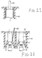
- a conventional connector of this kind comprises slots 12 which are disposed in a housing 10 to receive terminals 1, and a pair of lances 11' which are disposed in the slots to engage with and latch (primary latch) terminals inserted into the slots as shown in Figure 12.
- the terminals are temporarily latched by engaging steps formed at ends of the lances with rear portions of the terminals (a state shown in Figure 12).
- the terminals are set in a secondary or final latch state by separate means.
- the conventional connector When the terminal is to be released from the lance in the primary latch state, the conventional connector requires that the lance should be pried with a terminal extracting tool 20' which is inserted into an engaging part between the lance and the terminal in a direction reversed to an insertion direction of the terminal as shown in Figure 12.
- the conventional connector Since the conventional connector requires inserting the extracting tool into the housing, it is necessary to provide in the slot 12 a space for inserting the extracting tool. Accordingly, the conventional connector must include a pitch width which is rather large between adjacent terminals and has a large size when it comprises a large number of terminals. That is to say, the conventional connector can hardly be configured as a compact connector which comprises a large number of terminals arranged at a high density.
- U.S. patent no. 5,839,921 discloses a connector with a through hole for inserting a tool in order to remove the terminal.
- U.S. Patent no. 5,672,075 discloses a connecting terminal for insertion into a connector housing.
- the housing has a retaining lance and the terminal has a step portion with a constantly curving surface which has a configuration corresponding to the shape of a head of the retaining lance. The relationship between the terminal and the lance is such that the retaining force of the lance on the terminal is lowered.
- European patent EP 0 827 236 A1 discloses a connector with a contact which has an angular surface formed thereon.
- the connector has a housing with a retaining lance, a corner of which engages the angular surface formed on the contact.
- the present invention provides a connector according to claim 1.
- Figure 1 shows an embodiment of the connector according to the present invention.
- the connector preferred as the embodiment shown in Figure 1 accommodates terminals 1 in slots 12 which are disposed in a housing 10.
- Shown as the terminal is a receptacle type (female type) contact terminating with a wire material 2.
- This terminal (female type) is connected to a male type contact (round pin) (not shown) which is inserted in the direction reversed to the insertion direction of the terminal (female type).
- lances 11 Disposed in the slots are lances 11 which are to engage with the latch the inserted terminals. Though a pair of lances are disposed in the embodiment shown in Figure 1, the number of the lances is not limited. Only one lance may be disposed.
- the terminal is inserted upward from a bottom of Figure 1.
- the terminal which is inserted into the slot engages at a rear surface thereof (constricted portion) with a tip of the lance.
- the lance has a tip shape which is shown in detail in Figure 2.
- the lance is in a primary latch state where it temporarily latches the terminal and is in contact with a curved surface (rounded portion) formed on a rear of the terminal.
- the embodiment shown in the drawing has, in place of the step, a chamfer 11A which is formed at an inside corner of the tip.
- a shape of the lance which serves as a spring is not limited so far as it allows the terminal to pass elastically therethrough when the terminal is inserted into the housing.
- a sustaining plate disclosed by Japanese Patent Application Laid-Open No. 9-115584, for example, is available as secondary latch means.
- the sustaining plate serves to prevent the wire material of the terminal from coming off the connector after the terminal, which terminates with the wire material, is inserted through a through-hole formed in a body of the sustaining plate and then the body is slid in a direction intersecting with the insertion direction of the terminal so that the through-hole engages with the wire material of the terminal.
- the terminal When the terminal is inserted in an incorrect position or an incorrect direction in the primary latch state, the terminal can be released from the lance by applying a predetermined external force in a direction reversed to the insertion direction of the terminal (for example, with a tool described later).
- the external force is applied to the terminal.
- the external force applied to the terminal must be stronger than a retaining force of the lance which is determined by a contact angle with the terminal, a shape and a material or rigidity of the lance.
- Figure 3 shows relationship between a retaining force and a contact angle of the lance which has a definite shape and is made of a defined material.
- an ordinate is expressed in a coefficient.
- a reference numeral 20 represents a tool which is used to release the terminal from the lance by applying the external force. Since the terminal is a receptacle contact in the embodiment shown in the drawing, a through-hole is formed in the housing to insert a male type contact into the terminal (female type) in a direction reverse to the insertion direction of the terminal. The tool which is used to apply the external force to the terminal may be inserted through this through-hole 13.
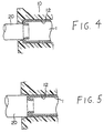
- Figure 4 shows a second embodiment of the present invention wherein a round type terminal (having a terminal body configured as a cylindrical receptacle contact having a ferrule formed at a tip) is released from a lance (not shown) by pushing the terminal with a round type tool.
- a round type terminal having a terminal body configured as a cylindrical receptacle contact having a ferrule formed at a tip
- the terminal has a narrow area to be brought into contact and pushed with the tool, whereby unnecessary force is applied to a contact portion and the terminal may be damaged when the terminal is pushed with the tool which is not brought into sufficient contact with the terminal.
- Figures 5 through 7 show a third embodiment of the present invention wherein a planar type tool is used for a round type terminal.
- Figure 5 is a longitudinal sectional view
- Figure 6 is a side view (the tool not shown)
- Figure 7 is a cross sectional view.
- Figures 9 through 11 show a fourth embodiment of the present invention wherein a planar type tool is used for a rectangular terminal. These embodiments provide sufficient areas of the terminals to be pushed with a tool.
- Figure 8 exemplifies a tool 20 which is to be used in the third embodiment.
- a blade type screwdriver for example, may be used as a tool.
- a pair of grooves 13A for receiving the tool are formed in inside wall surfaces opposed to each other of an opening 13 of a slot 12 in which the terminal is accommodated.
- Figures 5 and 7 show a condition where the tool is inserted into the grooves 13A.
- a circle inside the opening of the terminal slot indicates an inside diameter of the terminal (receptacle contact) (inside diameter of the ferrule) and a dashed line outside the opening indicates an outside diameter of the terminal.
- a reference numeral 13B represents a through-hole formed as a portion of the opening for passing a male type (round type) pin which is inserted into the terminal for connection thereto and a reference numeral 13b designates an inside wall surface of the through-hole.
- grooves 13A for receiving a tool are formed in inside wall surfaces opposed to each other of an opening 13 of a slot 12 which accommodates the terminal as in the third embodiment.
- the connector according to the present invention therefore provides a curved surface which is formed on a part of a terminal to be brought into contact with a lance. This allows the terminal to be released from the lance when a predetermined external force is applied to the terminal.
- the connector allows the terminal to be released simply by pushing a main body of the terminal with a tool such as a screwdriver, for example, which is inserted through an opening formed in the vicinity of an open end portion of the terminal and requires, unlike the conventional connector, reserving no space for inserting the tool into the terminal slot.
- the connector according to the present invention can have a short distance (pitch width) between adjacent terminals, thereby being configured as a compact connector which has a large numbers of terminals arranged at a high density.
- the connector according to the present invention does not require inserting the tool deep into a housing to prize the lance, thereby allowing the terminal to be released easily and efficiently.
Landscapes
- Engineering & Computer Science (AREA)
- Manufacturing & Machinery (AREA)
- Connector Housings Or Holding Contact Members (AREA)
- Manufacturing Of Electrical Connectors (AREA)
- Details Of Connecting Devices For Male And Female Coupling (AREA)
Claims (5)
- Connecteur comprenant une enveloppe (10) dotée de fentes (12) ayant chacune pour rôle de recevoir une borne (1), chaque fente contenant une patte (11) destinée à entrer en prise avec ladite borne insérée dans la fente et à la bloquer, une surface courbe (1A) étant formée sur une partie de ladite borne qui est en contact avec ladite patte, la patte ayant une forme pointue sur un coin intérieur de laquelle est formé un chanfrein (11A), la surface courbe (1A) de la borne faisant face au bord qui se trouve entre la pointe et le chanfrein, de telle sorte que la borne puisse être libérée de ladite patte par l'application d'une force externe prédéterminée sur ladite borne, dans un sens opposé au sens d'insertion de ladite borne.
- Connecteur selon la revendication 1, dans lequel ladite patte (11) a une surface de contact (11A) à une partie d'extrémité, ladite partie de contact étant en contact partiel avec ladite surface courbe (1A) de ladite borne.
- Connecteur selon la revendication 1 ou 2, dans lequel ladite force externe est déterminée en fonction d'au moins l'un des facteurs suivants : l'angle de contact (α) entre la patte (11) et la borne (1), la forme de la patte, et la qualité ou la rigidité du matériau.
- Connecteur selon l'une quelconque des revendications 1 à 3, dans lequel un trou débouchant (13) est formé dans ladite enveloppe (10) et ladite force externe peut être appliquée sur ladite borne insérée dans ladite fente au moyen d'un outil (20) inséré à travers le trou débouchant (13).
- Connecteur selon la revendication 4, dans lequel ledit trou débouchant (13) comprend, en outre, deux rainures (13A) formées dans des' surfaces internes, en regard l'une de l'autre, d'une ouverture (13B) de ladite fente (12), afin de recevoir ledit outil.
Applications Claiming Priority (2)
| Application Number | Priority Date | Filing Date | Title |
|---|---|---|---|
| JP11210820A JP2001052794A (ja) | 1999-07-26 | 1999-07-26 | コネクタ |
| JP21082099 | 1999-07-26 |
Publications (2)
| Publication Number | Publication Date |
|---|---|
| EP1073154A1 EP1073154A1 (fr) | 2001-01-31 |
| EP1073154B1 true EP1073154B1 (fr) | 2005-11-16 |
Family
ID=16595672
Family Applications (1)
| Application Number | Title | Priority Date | Filing Date |
|---|---|---|---|
| EP00306210A Expired - Lifetime EP1073154B1 (fr) | 1999-07-26 | 2000-07-21 | Connecteur électrique |
Country Status (7)
| Country | Link |
|---|---|
| US (1) | US6364705B1 (fr) |
| EP (1) | EP1073154B1 (fr) |
| JP (1) | JP2001052794A (fr) |
| KR (1) | KR20010015427A (fr) |
| AT (1) | ATE310324T1 (fr) |
| CA (1) | CA2314241C (fr) |
| DE (1) | DE60023999T2 (fr) |
Families Citing this family (5)
| Publication number | Priority date | Publication date | Assignee | Title |
|---|---|---|---|---|
| EP1378968B1 (fr) * | 2002-07-04 | 2007-11-07 | Sumitomo Wiring Systems, Ltd. | Connecteur |
| JP4440160B2 (ja) * | 2005-04-12 | 2010-03-24 | 矢崎総業株式会社 | コネクタ |
| KR100900269B1 (ko) * | 2007-03-19 | 2009-05-29 | 한국단자공업 주식회사 | 사이드랜스를 구비한 커넥터 |
| DE102014101952B4 (de) * | 2014-02-17 | 2018-02-01 | Phoenix Contact E-Mobility Gmbh | Steckverbinderteil mit einem Rastelement |
| JP6919598B2 (ja) * | 2018-03-05 | 2021-08-18 | 住友電装株式会社 | コネクタ |
Family Cites Families (8)
| Publication number | Priority date | Publication date | Assignee | Title |
|---|---|---|---|---|
| JPH081571Y2 (ja) * | 1990-03-05 | 1996-01-17 | 矢崎総業株式会社 | 端子係止具付コネクタ |
| JP2868405B2 (ja) * | 1994-02-16 | 1999-03-10 | 矢崎総業株式会社 | 雌型端子 |
| JP2921639B2 (ja) * | 1994-03-07 | 1999-07-19 | 矢崎総業株式会社 | 二重係止コネクタ及びその係止解除構造 |
| JPH0850947A (ja) | 1994-08-04 | 1996-02-20 | Yazaki Corp | 丸型端子用コネクタ |
| JP3188384B2 (ja) * | 1995-10-09 | 2001-07-16 | 矢崎総業株式会社 | コネクタ装置 |
| JPH09115644A (ja) | 1995-10-13 | 1997-05-02 | Yazaki Corp | 端子抜き取り治具およびコネクタハウジング |
| US5928034A (en) | 1996-07-30 | 1999-07-27 | Sumitomo Wiring Systems, Ltd. | Connector with terminal locking and locking assurance features |
| US5830013A (en) * | 1997-03-07 | 1998-11-03 | Yazaki Corporation | Electric connector |
-
1999
- 1999-07-26 JP JP11210820A patent/JP2001052794A/ja active Pending
-
2000
- 2000-04-20 US US09/553,497 patent/US6364705B1/en not_active Expired - Fee Related
- 2000-07-19 CA CA002314241A patent/CA2314241C/fr not_active Expired - Fee Related
- 2000-07-21 AT AT00306210T patent/ATE310324T1/de not_active IP Right Cessation
- 2000-07-21 EP EP00306210A patent/EP1073154B1/fr not_active Expired - Lifetime
- 2000-07-21 DE DE60023999T patent/DE60023999T2/de not_active Expired - Lifetime
- 2000-07-25 KR KR1020000042726A patent/KR20010015427A/ko not_active Application Discontinuation
Also Published As
| Publication number | Publication date |
|---|---|
| DE60023999T2 (de) | 2006-06-01 |
| ATE310324T1 (de) | 2005-12-15 |
| CA2314241C (fr) | 2009-03-24 |
| US6364705B1 (en) | 2002-04-02 |
| KR20010015427A (ko) | 2001-02-26 |
| JP2001052794A (ja) | 2001-02-23 |
| DE60023999D1 (de) | 2005-12-22 |
| CA2314241A1 (fr) | 2001-01-26 |
| EP1073154A1 (fr) | 2001-01-31 |
Similar Documents
| Publication | Publication Date | Title |
|---|---|---|
| EP1705755B1 (fr) | Connecteur électrique | |
| EP1094572B1 (fr) | Organe de contact et connecteur | |
| EP0676828A2 (fr) | Connecteur | |
| EP2530787A2 (fr) | Connecteur et son procédé d'assemblage | |
| US6981900B2 (en) | Connector and a terminal fitting | |
| EP1091450B1 (fr) | Connecteur | |
| KR200216959Y1 (ko) | 더블록크형 커넥터 | |
| US6368165B2 (en) | Connector | |
| EP1073154B1 (fr) | Connecteur électrique | |
| EP0723316A2 (fr) | Connecteur pour carte | |
| EP1204171B1 (fr) | Connecteur électrique | |
| EP1168518A2 (fr) | Connecteur | |
| US20020197894A1 (en) | Electrical connector | |
| KR20030031982A (ko) | 전기 플러그 연결부 | |
| EP1107381B1 (fr) | Connecteur | |
| US5655935A (en) | Receptacle contact used in an electrical connector | |
| EP1039952B1 (fr) | Partie de connecteur femelle pour boitier de stimulateur | |
| US6390849B1 (en) | Terminal holding structure | |
| US6000972A (en) | Structure for fixing terminal to connector housing | |
| JP2008130561A (ja) | 電気コネクタ | |
| EP0954059A1 (fr) | Connecteur électrique | |
| JPH10247543A (ja) | ターミナル | |
| JP3108310B2 (ja) | 誤結防止用ツメ栓 | |
| JP3260996B2 (ja) | 雌形端子金具 | |
| JP2024075244A (ja) | コネクタ |
Legal Events
| Date | Code | Title | Description |
|---|---|---|---|
| PUAI | Public reference made under article 153(3) epc to a published international application that has entered the european phase |
Free format text: ORIGINAL CODE: 0009012 |
|
| AK | Designated contracting states |
Kind code of ref document: A1 Designated state(s): AT BE CH CY DE DK ES FI FR GB GR IE IT LI LU MC NL PT SE |
|
| AX | Request for extension of the european patent |
Free format text: AL;LT;LV;MK;RO;SI |
|
| 17P | Request for examination filed |
Effective date: 20010709 |
|
| AKX | Designation fees paid |
Free format text: AT BE CH CY DE DK ES FI FR GB GR IE IT LI LU MC NL PT SE |
|
| RAP1 | Party data changed (applicant data changed or rights of an application transferred) |
Owner name: THOMAS & BETTS INTERNATIONAL, INC. |
|
| 17Q | First examination report despatched |
Effective date: 20030701 |
|
| GRAP | Despatch of communication of intention to grant a patent |
Free format text: ORIGINAL CODE: EPIDOSNIGR1 |
|
| GRAS | Grant fee paid |
Free format text: ORIGINAL CODE: EPIDOSNIGR3 |
|
| GRAA | (expected) grant |
Free format text: ORIGINAL CODE: 0009210 |
|
| AK | Designated contracting states |
Kind code of ref document: B1 Designated state(s): AT BE CH CY DE DK ES FI FR GB GR IE IT LI LU MC NL PT SE |
|
| PG25 | Lapsed in a contracting state [announced via postgrant information from national office to epo] |
Ref country code: NL Free format text: LAPSE BECAUSE OF FAILURE TO SUBMIT A TRANSLATION OF THE DESCRIPTION OR TO PAY THE FEE WITHIN THE PRESCRIBED TIME-LIMIT Effective date: 20051116 Ref country code: IT Free format text: LAPSE BECAUSE OF FAILURE TO SUBMIT A TRANSLATION OF THE DESCRIPTION OR TO PAY THE FEE WITHIN THE PRESCRIBED TIME-LIMIT;WARNING: LAPSES OF ITALIAN PATENTS WITH EFFECTIVE DATE BEFORE 2007 MAY HAVE OCCURRED AT ANY TIME BEFORE 2007. THE CORRECT EFFECTIVE DATE MAY BE DIFFERENT FROM THE ONE RECORDED. Effective date: 20051116 Ref country code: FI Free format text: LAPSE BECAUSE OF FAILURE TO SUBMIT A TRANSLATION OF THE DESCRIPTION OR TO PAY THE FEE WITHIN THE PRESCRIBED TIME-LIMIT Effective date: 20051116 Ref country code: LI Free format text: LAPSE BECAUSE OF FAILURE TO SUBMIT A TRANSLATION OF THE DESCRIPTION OR TO PAY THE FEE WITHIN THE PRESCRIBED TIME-LIMIT Effective date: 20051116 Ref country code: CH Free format text: LAPSE BECAUSE OF FAILURE TO SUBMIT A TRANSLATION OF THE DESCRIPTION OR TO PAY THE FEE WITHIN THE PRESCRIBED TIME-LIMIT Effective date: 20051116 Ref country code: AT Free format text: LAPSE BECAUSE OF FAILURE TO SUBMIT A TRANSLATION OF THE DESCRIPTION OR TO PAY THE FEE WITHIN THE PRESCRIBED TIME-LIMIT Effective date: 20051116 Ref country code: BE Free format text: LAPSE BECAUSE OF FAILURE TO SUBMIT A TRANSLATION OF THE DESCRIPTION OR TO PAY THE FEE WITHIN THE PRESCRIBED TIME-LIMIT Effective date: 20051116 |
|
| REG | Reference to a national code |
Ref country code: GB Ref legal event code: FG4D |
|
| REG | Reference to a national code |
Ref country code: CH Ref legal event code: EP |
|
| REG | Reference to a national code |
Ref country code: IE Ref legal event code: FG4D |
|
| REF | Corresponds to: |
Ref document number: 60023999 Country of ref document: DE Date of ref document: 20051222 Kind code of ref document: P |
|
| PG25 | Lapsed in a contracting state [announced via postgrant information from national office to epo] |
Ref country code: SE Free format text: LAPSE BECAUSE OF FAILURE TO SUBMIT A TRANSLATION OF THE DESCRIPTION OR TO PAY THE FEE WITHIN THE PRESCRIBED TIME-LIMIT Effective date: 20060216 Ref country code: DK Free format text: LAPSE BECAUSE OF FAILURE TO SUBMIT A TRANSLATION OF THE DESCRIPTION OR TO PAY THE FEE WITHIN THE PRESCRIBED TIME-LIMIT Effective date: 20060216 Ref country code: GR Free format text: LAPSE BECAUSE OF FAILURE TO SUBMIT A TRANSLATION OF THE DESCRIPTION OR TO PAY THE FEE WITHIN THE PRESCRIBED TIME-LIMIT Effective date: 20060216 |
|
| PG25 | Lapsed in a contracting state [announced via postgrant information from national office to epo] |
Ref country code: ES Free format text: LAPSE BECAUSE OF FAILURE TO SUBMIT A TRANSLATION OF THE DESCRIPTION OR TO PAY THE FEE WITHIN THE PRESCRIBED TIME-LIMIT Effective date: 20060227 |
|
| PG25 | Lapsed in a contracting state [announced via postgrant information from national office to epo] |
Ref country code: PT Free format text: LAPSE BECAUSE OF FAILURE TO SUBMIT A TRANSLATION OF THE DESCRIPTION OR TO PAY THE FEE WITHIN THE PRESCRIBED TIME-LIMIT Effective date: 20060417 |
|
| NLV1 | Nl: lapsed or annulled due to failure to fulfill the requirements of art. 29p and 29m of the patents act | ||
| REG | Reference to a national code |
Ref country code: CH Ref legal event code: PL |
|
| PG25 | Lapsed in a contracting state [announced via postgrant information from national office to epo] |
Ref country code: IE Free format text: LAPSE BECAUSE OF NON-PAYMENT OF DUE FEES Effective date: 20060721 |
|
| PG25 | Lapsed in a contracting state [announced via postgrant information from national office to epo] |
Ref country code: MC Free format text: LAPSE BECAUSE OF NON-PAYMENT OF DUE FEES Effective date: 20060731 |
|
| ET | Fr: translation filed | ||
| PLBE | No opposition filed within time limit |
Free format text: ORIGINAL CODE: 0009261 |
|
| STAA | Information on the status of an ep patent application or granted ep patent |
Free format text: STATUS: NO OPPOSITION FILED WITHIN TIME LIMIT |
|
| 26N | No opposition filed |
Effective date: 20060817 |
|
| REG | Reference to a national code |
Ref country code: IE Ref legal event code: MM4A |
|
| PG25 | Lapsed in a contracting state [announced via postgrant information from national office to epo] |
Ref country code: LU Free format text: LAPSE BECAUSE OF NON-PAYMENT OF DUE FEES Effective date: 20060721 |
|
| PG25 | Lapsed in a contracting state [announced via postgrant information from national office to epo] |
Ref country code: CY Free format text: LAPSE BECAUSE OF FAILURE TO SUBMIT A TRANSLATION OF THE DESCRIPTION OR TO PAY THE FEE WITHIN THE PRESCRIBED TIME-LIMIT Effective date: 20051116 |
|
| PGFP | Annual fee paid to national office [announced via postgrant information from national office to epo] |
Ref country code: FR Payment date: 20110805 Year of fee payment: 12 |
|
| PGFP | Annual fee paid to national office [announced via postgrant information from national office to epo] |
Ref country code: GB Payment date: 20110725 Year of fee payment: 12 Ref country code: DE Payment date: 20110727 Year of fee payment: 12 |
|
| GBPC | Gb: european patent ceased through non-payment of renewal fee |
Effective date: 20120721 |
|
| REG | Reference to a national code |
Ref country code: FR Ref legal event code: ST Effective date: 20130329 |
|
| PG25 | Lapsed in a contracting state [announced via postgrant information from national office to epo] |
Ref country code: DE Free format text: LAPSE BECAUSE OF NON-PAYMENT OF DUE FEES Effective date: 20130201 Ref country code: FR Free format text: LAPSE BECAUSE OF NON-PAYMENT OF DUE FEES Effective date: 20120731 Ref country code: GB Free format text: LAPSE BECAUSE OF NON-PAYMENT OF DUE FEES Effective date: 20120721 |
|
| REG | Reference to a national code |
Ref country code: DE Ref legal event code: R119 Ref document number: 60023999 Country of ref document: DE Effective date: 20130201 |