EP1072364A2 - Griff für ein Werkzeug - Google Patents
Griff für ein Werkzeug Download PDFInfo
- Publication number
- EP1072364A2 EP1072364A2 EP00115203A EP00115203A EP1072364A2 EP 1072364 A2 EP1072364 A2 EP 1072364A2 EP 00115203 A EP00115203 A EP 00115203A EP 00115203 A EP00115203 A EP 00115203A EP 1072364 A2 EP1072364 A2 EP 1072364A2
- Authority
- EP
- European Patent Office
- Prior art keywords
- handle
- cross
- sectional
- tool
- handle according
- Prior art date
- Legal status (The legal status is an assumption and is not a legal conclusion. Google has not performed a legal analysis and makes no representation as to the accuracy of the status listed.)
- Granted
Links
Images



Classifications
-
- B—PERFORMING OPERATIONS; TRANSPORTING
- B25—HAND TOOLS; PORTABLE POWER-DRIVEN TOOLS; MANIPULATORS
- B25G—HANDLES FOR HAND IMPLEMENTS
- B25G1/00—Handle constructions
- B25G1/10—Handle constructions characterised by material or shape
- B25G1/105—Handle constructions characterised by material or shape for screwdrivers, wrenches or spanners
Definitions
- screwdriver handles or similar tools There are a variety of different screwdriver handles or similar tools.
- the oldest screwdriver have a circular cross-section and approximately convex longitudinal section.
- cross sections on a division of two or are based on a division of three include cross sections in Shape of a flattened circle as well as triangular and hexagonal Cross sections.
- the polygonal cross sections are chosen been used to improve the transmission of torques.
- a booklet for hand tools is already known (DE 9202672), which has a pentagonal cross section.
- the Edges of the pentagonal cross-section are rounded, whereby the arc length of the rounded part of the cross-section everywhere is essentially the same.
- the invention is based, an ergonomic task Regarded improved grip for a screwdriver or to create a similar tool with which too a torque is to be transmitted.
- Tools of this kind are, for example, screw clamps in which to clamp a screwing movement must also be carried out, moreover Chisels, files, hacksaws or the like, in which, for example a twist must be prevented, which means that torque is also applied must to prevent rotation.
- the invention proposes a tool handle with the features of claim 1. Training the invention are the subject of the dependent claims, their wording as well as the wording of the summary made by reference to the content of the description becomes.
- the shape of the handle is better to the adapted to human hand. Only in the end areas where a user attacks for support is the pentagonal Form not available.
- the invention prefers the cross section in the form of an approximate regular pentagon.
- a Symmetry is not required, for example, with a Handle for a hacksaw, can also be an irregular pentagon Find use.
- the Cross-sectional shape has rounded corner portions that on a circular arc with one in the longitudinal axis of the handle lying center point. So the pentagons will not fully trained but their sides are rounded by Sections joined together.
- these sides of the approximate pentagonal shape slightly curved, with a much larger one Radius than the rounded corner sections.
- the sides of the cross-sectional shape can be rectilinear be trained.
- the end cap of the handle that closes the handle serves to that the user can rest on the handle. Possibly can also be used to some extent To exert a feed movement on the handle or the workpiece, if, for example, a screw is screwed into wood shall be. Since this is not the point here Transmission of torques on the handle can be done according to the invention the cross section of the handle in the area of the end cap go into a circle.
- the handle two places of a local cross-sectional maximum from which the handle in the respective end areas passes, namely the end face assigned to the workpiece and the tip. At least between these two places a larger cross-section or diameter should according to the invention the pentagonal shape of the cross section will be present.
- the shape of the tool handle can be determined by a rotationally symmetrical Body with longitudinal flats being represented.
- the Tool handle a point of a first cross-sectional maximum has a distance from the tip end of the handle about 30% of the length of the handle.
- the tool handle have a point of a second cross-sectional maximum, a distance of about from the tip end of the handle 60% to 70% of the length of the handle.
- the length of the handle is to be understood as the length available to the user to attack, So starting from the end of the crest to a point where the user supports his thumb and possibly the index finger.
- the Diameter of the tool handle at the point of the first cross-sectional maximum is about 15% to 18% larger than on the Place of the second maximum.
- the Longitudinal profile of the tool handle from the position of the second Cross-sectional maximum is concave, preferably up to the end of the handle assigned to the tool. In this Area, the tool can either be rotated quickly or support the fingers.
- the smallest diameter of the handle between the position of the second Cross-sectional maximums and the one assigned to the tool End of the handle.
- the maximum diameter of the handle is about 70% to 80% larger than that smallest diameter of the handle.
- the Surface at least part of the length of the handle is softer than in the area of the free handle end.
- the material of the handle itself is up to the surface available.
- the softer surface can, for example, by a coating or be produced in any other way.
- the free end of the handle preferably forms a semicircle Striking cap.
- the handle body is essentially complete made of impact resistant polypropylene, while the softer Surface have a Shore hardness of about 75 to 85 can.
- the handle body can be an elastomer Trade polyolefin base.
- the softer area the surface between the two maximum diameters extends or in other words in the area of Griffs, where it has its pentagonal cross section.
- Figure 1 shows a perspective view of a screwdriver handle without the blade leading to a screwdriver heard.
- the handle extends from one to the front left seeing face 1, from which the blade normally protrudes from the tool along a longitudinal axis to one End cap 2.
- the end cap 2 has a convex shape on.
- the length of the handle corresponds approximately to the width of one human hand. Depending on the size of the blade, the approximate the size of the screw to be operated can be adjusted the size of the handle also vary somewhat.
- Figure 2 now shows a side view of the handle.
- the handle appears to be asymmetrical. This follows from the cross-sectional shape of the pentagon since the side view For example, a contour on the left shows the corners the pentagons follow, while on the right the flat side of the pentagons comes to rest.
- the handle begins in Figure 2 at the rear End in a circular cross section, see the Section of Figure 4. From there, progressively becomes the Level 5, the cross-sectional shape gradually pentagonal, the the position perpendicular to the longitudinal axis plane V-V shows where the handle has its largest cross section. This Section is shown in Figure 5.
- the diameter decreases from the cross-sectional plane V on or the size of the cross-section again up to the transverse plane VI where the size of the cross section is a local minimum reached.
- This cross section is shown in FIG. 6. Also here you can see that the side surfaces of the handle in the Cross-section formed by straight lines 3 are, while the edges 4 more or less rounded are.
- the grip Due to the pentagonal cross-sectional shape in the part of the handle, in which the user with the closed hand for transmission torque, the grip is better on the anatomical structure of a human hand adapted, see above that even with prolonged use of a screwdriver result in fewer signs of fatigue.
- the handle is essentially a one-piece body formed, preferably made of impact-resistant polypropylene.
- the surface of the handle is softer, for example by extrusion coating with an elastomer the Shore hardness from 75 to 85.
- the softer surface improves the handling of the handle.
- the hard base remains in the area of the end 2 also preserved on the surface, so this end as Striking can serve.
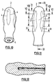
- FIG. 10 shows a tool handle in perspective of the invention, such as for a screwdriver can be used.
- the screwdriver shaft is not shown.
- the handle can also be used Clamping screw clamps, as a handle for hacksaws, as Handle for chisels or files can be used. With these Tools are about either a rotating or perform screwing movement, or a tool secure against rotation, which is also by spending of a torque must be reached.
- the tool handle extends from an end face 1 from which the A screwdriver shaft would come out along one Longitudinal axis to an opposite free end 2.
- the handle In the area of the free end 2, the handle is rounded and forms thereby a knoll. This crest lies when using the Tools on the palm of your hand or on the bale. Between these The tool handle has a position on both ends Cross-sectional maximums, which in Figure 11 through the plane VI-VI is shown. The distance of this plane from the end of the crest 2 of the tool handle is approximately 30% of the length of the handle. Under the length of the handle is the distance between the Free end and the front face 1 to understand.
- the handle has an enlarged diameter, on which a user holds his index finger or Can support your thumb. It would be conceivable from this face 1 starting to extend the handle without this for using the handle while turning or screwing would have an impact. Such an extension is said to Calculation of the length of the handle should not be included.
- the handle points away from the point of greatest diameter a second digit with a cross-sectional maximum, in Figure 11, the level IV-IV. Between these two levels is a point in Figure 11, the level V-V exists at which there is a local cross-sectional minimum.
- the flats 13 end in the area of the location of the second Cross-sectional maximums. At this point the cross section the handle is circular again. Then decreases the value of the diameter gradually up to the plane C, where the diameter is at a minimum. Then enlarged the diameter again. This will make the longitudinal profile between the plane IV-IV and the front end 1 concave.
- the longitudinal section of FIG. 12 is through the longitudinal axis layer containing the handle. From the comparison of the one can use the asymmetry of the right to the two outer contours Recognize the left outer contour.
- FIG. 13 corresponds to level IV-IV in FIG. 11. At this point it starts towards the tool end of the Handle the zone with the concave outer contour in longitudinal section on. In the opposite direction, the section of the Handle in which the flats 13 are present.
- Figure 14 shows a section through the location of the Cross section maximums corresponding to level V-V.
- the flats 13 are the side of a regular one Form pentagon. These straight lines of the pentagon are together by curved corner sections 16 connected in which the cross-sectional contour on a Circle lie, the center of which in the longitudinal axis 17 of the Tool handle lies.
- the total length is Handle, starting from the face level 1, 105 mm. This is a usual size for screwdrivers.
- Level VIII starting from the end plane 1, has one Distance of 17 mm on, level VII a distance of 38 mm, the plane VI a distance of 52 mm, the plane V a distance of 72 mm and level IV a distance of 95 mm.
- the radius of curvature of the outer contour in side view is between about 17 mm and about 25 mm.
- the diameter of the handle in the embodiment just mentioned is about 26 mm in level IV if one takes the diameter of the circle in which the Pentagon is inscribed.
- the diameter is about 36 mm in the Level VI at about 30 mm, in level VII at about 31 mm and in plane VIII at about 20 mm.
- Figure 2 shows a side view of the screwdriver handle from a direction parallel to one side of the Pentagon runs, which is the cross-sectional shape of the handle forms. It also follows that the figure in FIG seeing left side edge not symmetrical to the right Side edge runs.
- FIG. 9 now shows the handle from a different direction, namely from a direction that runs radially and so arranged is that a rounded side edge 4 in the Middle is arranged. This now results in a symmetrical one Shape of the screwdriver handle.
- the handle is circular in the area of its axial ends Cross-section, which then gradually into the pentagonal Cross-section passes, the areas 7 have about Handle length different widths, what else through the rounding of the edges 4 of the handle is reinforced. This results in the shape of the Handle.
Landscapes
- Engineering & Computer Science (AREA)
- Mechanical Engineering (AREA)
- Details Of Spanners, Wrenches, And Screw Drivers And Accessories (AREA)
- Food-Manufacturing Devices (AREA)
- Portable Power Tools In General (AREA)
- Gripping Jigs, Holding Jigs, And Positioning Jigs (AREA)
- Hand Tools For Fitting Together And Separating, Or Other Hand Tools (AREA)
- Knives (AREA)
Abstract
Description
- Fig. 1
- eine perspektivische Ansicht eines Schraubendrehergriffs nach der Erfindung;
- Fig. 2
- eine Seitenansicht des Schraubendrehergriffs der Figur 1;
- Fig. 3
- eine Stirnansicht des Schraubendrehergriffs von unten in Figur 2;
- Fig. 4
- einen Schnitt längs Linie IV-IV in Figur 2;
- Fig. 5
- einen Schnitt durch die Stelle des Handgriffs, wo dieser ein Querschnittsmaximum aufweist;
- Fig. 6
- einen Schnitt längs Linie VI-VI in Figur 2;
- Fig. 7
- einen Schnitt längs Linie VII-VII in Figur 2;
- Fig. 8
- einen Querschnitt durch die Stelle kurz vor der dem Werkstück zugeordneten Stirnfläche, wo der Griff seinen kleinsten Durchmesser aufweist;
- Fig. 9
- eine der Figur 2 entsprechende Seitenansicht.
- Fig. 10
- eine perspektivische Ansicht eines Werkzeuggriffs nach der Erfindung;
- Fig. 11
- eine Seitenansicht des Werkzeuggriffs nach der Erfindung;
- Fig. 12
- einen Längsschnitt durch den Werkzeuggriff;
- Fig. 13
- bis Figur 18 Querschnitte durch den Werkzeuggriff in verschiedenen Ebenen, die in Figur 11 angedeutet sind.
Claims (20)
- Werkzeuggriff, insbesondere für Schraubendreher, der
- 1.1
- sich längs einer Längsachse von einer dem Werkzeug zugeordneten Stirnfläche (1) bis zu einer abgerundeten Kuppe (2) erstreckt und
- 1.2
- über einen wesentlichen Teil seiner Länge einen Querschnitt etwa in Form eines Fünfecks aufweist, wobei
- 1.3
- die Orientierung des Fünfecks sich über die Länge des Griffs nicht ändert.
- Griff nach Anspruch 1, bei dem der Querschnitt des Griffs im Bereich der Endkuppe (2) und/oder im Bereich der dem Werkstück zugeordneten Stirnfläche (1) in einen Kreis übergeht.
- Griff nach Anspruch 1 oder 2, mit zwei Stellen (V, VII) eines Querschnittsmaximums, von dem aus der Griff in die jeweiligen Endbereiche übergeht, wobei die Fünfeckform mindestens zwischen diesen beiden Stel-len (V, VII) vorhanden ist.
- Griff nach Anspruch 3, mit einer Stelle eines Querschnittsminimums zwischen der dem Werkstück zugeordneten Stirnfläche (1) und dem benachbarten Querschnittsmaximum (VII), wobei das Querschnittsminimum die Querschnittsform eines Kreises aufweist.
- Griff nach Anspruch 3 oder 4, mit einer Stelle (VI) eines lokalen Querschnittsminimums zwischen den beiden Stellen (V, VII) des Querschnittsmaximums.
- Werkzeuggriff nach einem der vorhergehenden Ansprüche, bei dem die Querschnittsform abgerundete Eckenabschnitte aufweist, die auf einem Kreisbogen mit einem in der Längsachse des Griffs lie-genden Mittelpunkt liegen.
- Werkzeuggriff nach Anspruch 6, bei dem die bogenförmigen Eckenabschnitte der Querschnittsform durch geradlinig bis konvex verlaufende Seiten verbunden sind.
- Werkzeuggriff nach einem der vorhergehenden Ansprüche, bei dem der Querschnitt im restlichen Teil der Länge des Griffs kreisrund ist.
- Werkzeuggriff nach einem der vorhergehenden Ansprüche, bei dem die Form durch einen rotationssymmetrischen Körper mit in Längsrichtung verlaufenden Abflachungen (3) gebildet ist.
- Werkzeuggriff nach einem der vorhergehenden Ansprüche, bei dem eine den Übergang zwischen den bogenförmigen Eckabschnitten und den insbesondere geradlinig verlaufenden Seiten der Querschnittsform verbindende Linie (4) nicht der Längskontur des Griffs folgt.
- Werkzeuggriff nach einem der vorhergehenden Ansprüche, mit einer Stelle (VI) eines ersten Querschnittsmaximums, die von dem Kuppenende (2) des Griffs einen Abstand von etwa 30 % der Länge des Griffs aufweist.
- Werkzeuggriff nach einem der vorhergehenden Ansprüche, mit einer Stelle (IV) eines zweiten Querschnittsmaximums, die von dem Kuppenende (2) des Griffs einenAbstand von etwa 60 % bis 70 % der Länge des Griffs aufweist.
- Werkzeuggriff nach einem der vorhergehenden Ansprüche, bei dem der Durchmesser des Griffs an der Stelle (VI) des ersten Querschnittsmaximums etwa 15 % bis 18 % größer ist als an der Stelle (IV) des zweiten Querschnittsmaximums.
- Werkzeuggriff nach einem der Ansprüche 12 oder 13, bei dem die etwa fünfeckige Querschnittsform an der Stelle (IV) des zweiten Querschnittsmaximums endet.
- Werkzeuggriff nach einem der Ansprüche 12 bis 14, bei dem das Längsprofil von der Stelle (IV) des zweiten Querschnittsmaximums an konkav ausgebildet ist, vorzugsweise bis zu dem dem Werkzeug zugeordneten Ende (1) des Griffs.
- Werkzeuggriff nach einem der Ansprüche 12 bis 15, bei dem der kleinste Durchmesser des Griffs zwischen der Stelle (IV) des zweiten Querschnittsmaximums und dem dem Werkzeug zugeordneten Ende (1) des Griffs liegt.
- Werkzeuggriff nach einem der vorhergehenden Ansprüche, bei dem der maximale Durchmesser des Griffs etwa 70 % bis 80 % größer ist als der kleinste Durchmesser.
- Griff nach einem der vorhergehenden Ansprüche, bei dem die Oberfläche mindestens über einen Teil der axialen Länge des Griffs weicher ist als im Bereich des Endes (2) des Griffs.
- Griff nach Anspruch 18, bei dem die weichere Oberfläche im Bereich zwischen den beiden äußeren Querschnittsmaxima (V, VII) vorgesehen ist.
- Griff nach Anspruch 18 oder 19, bei dem die weichere Oberfläche in dem Bereich des Griffs vorgesehen ist, in dem dieser seinen fünfeckigen Querschnitt aufweist.
Applications Claiming Priority (4)
| Application Number | Priority Date | Filing Date | Title |
|---|---|---|---|
| DE19934525A DE19934525A1 (de) | 1999-07-22 | 1999-07-22 | Griff für einen Schraubendreher |
| DE19934525 | 1999-07-22 | ||
| DE10001885 | 2000-01-19 | ||
| DE10001885A DE10001885A1 (de) | 1999-07-22 | 2000-01-19 | Griff für ein Werkzeug |
Publications (3)
| Publication Number | Publication Date |
|---|---|
| EP1072364A2 true EP1072364A2 (de) | 2001-01-31 |
| EP1072364A3 EP1072364A3 (de) | 2001-08-08 |
| EP1072364B1 EP1072364B1 (de) | 2006-02-15 |
Family
ID=26003901
Family Applications (1)
| Application Number | Title | Priority Date | Filing Date |
|---|---|---|---|
| EP00115203A Expired - Lifetime EP1072364B1 (de) | 1999-07-22 | 2000-07-13 | Griff für ein Werkzeug |
Country Status (4)
| Country | Link |
|---|---|
| EP (1) | EP1072364B1 (de) |
| AT (1) | ATE317746T1 (de) |
| DE (2) | DE10001885A1 (de) |
| ES (1) | ES2257242T3 (de) |
Cited By (1)
| Publication number | Priority date | Publication date | Assignee | Title |
|---|---|---|---|---|
| WO2006097181A1 (de) | 2005-03-18 | 2006-09-21 | Carl Freudenberg Kg | Handhabungselement für ein reinigungsgerät |
Family Cites Families (7)
| Publication number | Priority date | Publication date | Assignee | Title |
|---|---|---|---|---|
| DE3004957A1 (de) * | 1980-02-09 | 1981-08-20 | Fa. W. Holland-Letz, 5608 Radevormwald | Griff fuer einhaddrehwerkzeuge |
| DE8110659U1 (de) * | 1981-04-08 | 1981-10-01 | ELORA-Werkzeugfabrik GmbH, 5630 Remscheid | "werkzeugheft" |
| DE3525163A1 (de) * | 1985-07-13 | 1987-01-22 | Werner Hermann Wera Werke | Werkzeugheft, insbesondere fuer schraubendreher |
| DE8711988U1 (de) * | 1987-09-04 | 1988-01-14 | Felo-Werkzeugfabrik Holland-Letz GmbH, 3577 Neustadt | Schraubendrehergriff |
| DE4037592A1 (de) * | 1989-11-28 | 1991-05-29 | Manfred Lauber | Werkzeuggriff fuer werkzeuge, insbesondere schraubendreher |
| DE9202672U1 (de) * | 1992-02-29 | 1993-03-25 | W. Holland-Letz GmbH & Co KG, 5608 Radevormwald | Heft für Handwerkzeuge |
| DE29701734U1 (de) * | 1997-01-17 | 1997-07-17 | Willi Hahn GmbH & Co KG, 78136 Schonach | Drehwerkzeug-System |
-
2000
- 2000-01-19 DE DE10001885A patent/DE10001885A1/de not_active Withdrawn
- 2000-07-13 ES ES00115203T patent/ES2257242T3/es not_active Expired - Lifetime
- 2000-07-13 AT AT00115203T patent/ATE317746T1/de not_active IP Right Cessation
- 2000-07-13 DE DE50012215T patent/DE50012215D1/de not_active Expired - Lifetime
- 2000-07-13 EP EP00115203A patent/EP1072364B1/de not_active Expired - Lifetime
Cited By (2)
| Publication number | Priority date | Publication date | Assignee | Title |
|---|---|---|---|---|
| WO2006097181A1 (de) | 2005-03-18 | 2006-09-21 | Carl Freudenberg Kg | Handhabungselement für ein reinigungsgerät |
| NO337803B1 (no) * | 2005-03-18 | 2016-06-27 | Freudenberg Carl Kg | Håndteringselementer for rengjøringsredskap |
Also Published As
| Publication number | Publication date |
|---|---|
| DE10001885A1 (de) | 2001-07-26 |
| EP1072364A3 (de) | 2001-08-08 |
| ATE317746T1 (de) | 2006-03-15 |
| ES2257242T3 (es) | 2006-08-01 |
| DE50012215D1 (de) | 2006-04-20 |
| EP1072364B1 (de) | 2006-02-15 |
Similar Documents
| Publication | Publication Date | Title |
|---|---|---|
| WO2001053046A1 (de) | Griff für ein werkzeug | |
| DE102007027733B4 (de) | Rutschfeste Nuss mit gleichförmiger Wanddicke | |
| DE60124430T2 (de) | Einsatz zum entfernen von beschädigten schrauben | |
| DE1478789A1 (de) | Mitnehmer fuer Befestigungsmittel mit einem mit Nuten versehenen Kopfstueck | |
| EP0062270A2 (de) | Werkzeugheft | |
| EP1072364B1 (de) | Griff für ein Werkzeug | |
| DE19541786B4 (de) | Steckschlüsseleinsatz | |
| DE19511870A1 (de) | Schraubendreher mit ummanteltem Klingenschaft | |
| DE8716099U1 (de) | Schraubendreher | |
| EP0254135A1 (de) | Schraubenschlüssel | |
| DE4037592A1 (de) | Werkzeuggriff fuer werkzeuge, insbesondere schraubendreher | |
| DE2214466A1 (de) | Aus einem Schraubenzieher und Schraubengreifer bestehendes kombiniertes Werkzeug | |
| DE10011771B4 (de) | Schraubwerkzeug | |
| DE19934525A1 (de) | Griff für einen Schraubendreher | |
| DE102005010464B4 (de) | Greifzange | |
| EP0952902B1 (de) | Drehwerkzeug-system | |
| DE4434820A1 (de) | Wandhalterung für Arbeitsgeräte mit Stiel | |
| DE102005052694A1 (de) | Drehantriebsausbildung | |
| DE69406031T2 (de) | Schraubenzieher | |
| DE10359742B4 (de) | Kombinationszange | |
| DE10045649A1 (de) | Griff für eine Knarre | |
| DE29720608U1 (de) | Werkzeugheft | |
| DE102008041911A1 (de) | Ratschenschlüssel | |
| DE102024130244A1 (de) | Schraubwerkzeug mit in einer Hülse steckenden Klinge | |
| DE1575167C (de) | Bohrschraube |
Legal Events
| Date | Code | Title | Description |
|---|---|---|---|
| PUAI | Public reference made under article 153(3) epc to a published international application that has entered the european phase |
Free format text: ORIGINAL CODE: 0009012 |
|
| AK | Designated contracting states |
Kind code of ref document: A2 Designated state(s): AT BE CH CY DE DK ES FI FR GB GR IE IT LI LU MC NL PT SE |
|
| AX | Request for extension of the european patent |
Free format text: AL;LT;LV;MK;RO;SI |
|
| PUAL | Search report despatched |
Free format text: ORIGINAL CODE: 0009013 |
|
| AK | Designated contracting states |
Kind code of ref document: A3 Designated state(s): AT BE CH CY DE DK ES FI FR GB GR IE IT LI LU MC NL PT SE |
|
| AX | Request for extension of the european patent |
Free format text: AL;LT;LV;MK;RO;SI |
|
| 17P | Request for examination filed |
Effective date: 20011123 |
|
| AKX | Designation fees paid |
Free format text: AT BE CH CY DE DK ES FI FR GB GR IE IT LI LU MC NL PT SE |
|
| 17Q | First examination report despatched |
Effective date: 20031021 |
|
| GRAP | Despatch of communication of intention to grant a patent |
Free format text: ORIGINAL CODE: EPIDOSNIGR1 |
|
| GRAS | Grant fee paid |
Free format text: ORIGINAL CODE: EPIDOSNIGR3 |
|
| GRAA | (expected) grant |
Free format text: ORIGINAL CODE: 0009210 |
|
| AK | Designated contracting states |
Kind code of ref document: B1 Designated state(s): AT BE CH CY DE DK ES FI FR GB GR IE IT LI LU MC NL PT SE |
|
| PG25 | Lapsed in a contracting state [announced via postgrant information from national office to epo] |
Ref country code: GB Free format text: LAPSE BECAUSE OF FAILURE TO SUBMIT A TRANSLATION OF THE DESCRIPTION OR TO PAY THE FEE WITHIN THE PRESCRIBED TIME-LIMIT Effective date: 20060215 Ref country code: IE Free format text: LAPSE BECAUSE OF FAILURE TO SUBMIT A TRANSLATION OF THE DESCRIPTION OR TO PAY THE FEE WITHIN THE PRESCRIBED TIME-LIMIT Effective date: 20060215 |
|
| REG | Reference to a national code |
Ref country code: GB Ref legal event code: FG4D Free format text: NOT ENGLISH Ref country code: CH Ref legal event code: EP |
|
| REG | Reference to a national code |
Ref country code: IE Ref legal event code: FG4D Free format text: LANGUAGE OF EP DOCUMENT: GERMAN |
|
| REF | Corresponds to: |
Ref document number: 50012215 Country of ref document: DE Date of ref document: 20060420 Kind code of ref document: P |
|
| PG25 | Lapsed in a contracting state [announced via postgrant information from national office to epo] |
Ref country code: DK Free format text: LAPSE BECAUSE OF FAILURE TO SUBMIT A TRANSLATION OF THE DESCRIPTION OR TO PAY THE FEE WITHIN THE PRESCRIBED TIME-LIMIT Effective date: 20060515 Ref country code: SE Free format text: LAPSE BECAUSE OF FAILURE TO SUBMIT A TRANSLATION OF THE DESCRIPTION OR TO PAY THE FEE WITHIN THE PRESCRIBED TIME-LIMIT Effective date: 20060515 |
|
| PG25 | Lapsed in a contracting state [announced via postgrant information from national office to epo] |
Ref country code: PT Free format text: LAPSE BECAUSE OF FAILURE TO SUBMIT A TRANSLATION OF THE DESCRIPTION OR TO PAY THE FEE WITHIN THE PRESCRIBED TIME-LIMIT Effective date: 20060717 |
|
| PGFP | Annual fee paid to national office [announced via postgrant information from national office to epo] |
Ref country code: NL Payment date: 20060718 Year of fee payment: 7 |
|
| PG25 | Lapsed in a contracting state [announced via postgrant information from national office to epo] |
Ref country code: CH Free format text: LAPSE BECAUSE OF NON-PAYMENT OF DUE FEES Effective date: 20060731 Ref country code: MC Free format text: LAPSE BECAUSE OF NON-PAYMENT OF DUE FEES Effective date: 20060731 Ref country code: LI Free format text: LAPSE BECAUSE OF NON-PAYMENT OF DUE FEES Effective date: 20060731 Ref country code: BE Free format text: LAPSE BECAUSE OF NON-PAYMENT OF DUE FEES Effective date: 20060731 |
|
| REG | Reference to a national code |
Ref country code: ES Ref legal event code: FG2A Ref document number: 2257242 Country of ref document: ES Kind code of ref document: T3 |
|
| GBV | Gb: ep patent (uk) treated as always having been void in accordance with gb section 77(7)/1977 [no translation filed] |
Effective date: 20060215 |
|
| REG | Reference to a national code |
Ref country code: IE Ref legal event code: FD4D |
|
| ET | Fr: translation filed | ||
| PLBE | No opposition filed within time limit |
Free format text: ORIGINAL CODE: 0009261 |
|
| STAA | Information on the status of an ep patent application or granted ep patent |
Free format text: STATUS: NO OPPOSITION FILED WITHIN TIME LIMIT |
|
| 26N | No opposition filed |
Effective date: 20061116 |
|
| REG | Reference to a national code |
Ref country code: CH Ref legal event code: PL |
|
| PG25 | Lapsed in a contracting state [announced via postgrant information from national office to epo] |
Ref country code: AT Free format text: LAPSE BECAUSE OF NON-PAYMENT OF DUE FEES Effective date: 20060713 |
|
| BERE | Be: lapsed |
Owner name: ADOLF WURTH G.M.B.H. & CO. KG Effective date: 20060731 |
|
| NLV4 | Nl: lapsed or anulled due to non-payment of the annual fee |
Effective date: 20080201 |
|
| PG25 | Lapsed in a contracting state [announced via postgrant information from national office to epo] |
Ref country code: NL Free format text: LAPSE BECAUSE OF NON-PAYMENT OF DUE FEES Effective date: 20080201 |
|
| PG25 | Lapsed in a contracting state [announced via postgrant information from national office to epo] |
Ref country code: LU Free format text: LAPSE BECAUSE OF NON-PAYMENT OF DUE FEES Effective date: 20060713 |
|
| PG25 | Lapsed in a contracting state [announced via postgrant information from national office to epo] |
Ref country code: CY Free format text: LAPSE BECAUSE OF FAILURE TO SUBMIT A TRANSLATION OF THE DESCRIPTION OR TO PAY THE FEE WITHIN THE PRESCRIBED TIME-LIMIT Effective date: 20060215 |
|
| PGFP | Annual fee paid to national office [announced via postgrant information from national office to epo] |
Ref country code: GR Payment date: 20060731 Year of fee payment: 7 |
|
| PG25 | Lapsed in a contracting state [announced via postgrant information from national office to epo] |
Ref country code: GR Free format text: LAPSE BECAUSE OF NON-PAYMENT OF DUE FEES Effective date: 20070731 |
|
| REG | Reference to a national code |
Ref country code: FR Ref legal event code: TP Owner name: WURTH INTERNATIONAL AG, CH Effective date: 20120625 |
|
| REG | Reference to a national code |
Ref country code: ES Ref legal event code: PC2A Owner name: WUERTH INTERNATIONAL AG Effective date: 20120906 |
|
| PGFP | Annual fee paid to national office [announced via postgrant information from national office to epo] |
Ref country code: FI Payment date: 20120711 Year of fee payment: 13 |
|
| PGFP | Annual fee paid to national office [announced via postgrant information from national office to epo] |
Ref country code: IT Payment date: 20120726 Year of fee payment: 13 Ref country code: FR Payment date: 20120806 Year of fee payment: 13 Ref country code: ES Payment date: 20120713 Year of fee payment: 13 |
|
| REG | Reference to a national code |
Ref country code: FR Ref legal event code: ST Effective date: 20140331 |
|
| PG25 | Lapsed in a contracting state [announced via postgrant information from national office to epo] |
Ref country code: FI Free format text: LAPSE BECAUSE OF NON-PAYMENT OF DUE FEES Effective date: 20130713 |
|
| PG25 | Lapsed in a contracting state [announced via postgrant information from national office to epo] |
Ref country code: FR Free format text: LAPSE BECAUSE OF NON-PAYMENT OF DUE FEES Effective date: 20130731 Ref country code: IT Free format text: LAPSE BECAUSE OF NON-PAYMENT OF DUE FEES Effective date: 20130713 |
|
| REG | Reference to a national code |
Ref country code: ES Ref legal event code: FD2A Effective date: 20141016 |
|
| PG25 | Lapsed in a contracting state [announced via postgrant information from national office to epo] |
Ref country code: ES Free format text: LAPSE BECAUSE OF NON-PAYMENT OF DUE FEES Effective date: 20130714 |
|
| PGFP | Annual fee paid to national office [announced via postgrant information from national office to epo] |
Ref country code: DE Payment date: 20160722 Year of fee payment: 17 |
|
| REG | Reference to a national code |
Ref country code: DE Ref legal event code: R119 Ref document number: 50012215 Country of ref document: DE |
|
| PG25 | Lapsed in a contracting state [announced via postgrant information from national office to epo] |
Ref country code: DE Free format text: LAPSE BECAUSE OF NON-PAYMENT OF DUE FEES Effective date: 20180201 |