EP1069773A2 - Kopierschutzverfahren, Informationssignalbearbeitungssystem, Informationssignalausgabeanlage, Informationssignalbearbeitungsanlage, Informationssignalausgabeverfahren, Informationssignalbearbeitungsverfahren, und Informationssignalaufnahmemedium - Google Patents
Kopierschutzverfahren, Informationssignalbearbeitungssystem, Informationssignalausgabeanlage, Informationssignalbearbeitungsanlage, Informationssignalausgabeverfahren, Informationssignalbearbeitungsverfahren, und Informationssignalaufnahmemedium Download PDFInfo
- Publication number
- EP1069773A2 EP1069773A2 EP00305978A EP00305978A EP1069773A2 EP 1069773 A2 EP1069773 A2 EP 1069773A2 EP 00305978 A EP00305978 A EP 00305978A EP 00305978 A EP00305978 A EP 00305978A EP 1069773 A2 EP1069773 A2 EP 1069773A2
- Authority
- EP
- European Patent Office
- Prior art keywords
- information
- additional
- information signal
- signal
- additional information
- Prior art date
- Legal status (The legal status is an assumption and is not a legal conclusion. Google has not performed a legal analysis and makes no representation as to the accuracy of the status listed.)
- Withdrawn
Links
Images


Classifications
-
- H—ELECTRICITY
- H04—ELECTRIC COMMUNICATION TECHNIQUE
- H04N—PICTORIAL COMMUNICATION, e.g. TELEVISION
- H04N21/00—Selective content distribution, e.g. interactive television or video on demand [VOD]
- H04N21/80—Generation or processing of content or additional data by content creator independently of the distribution process; Content per se
- H04N21/81—Monomedia components thereof
- H04N21/8106—Monomedia components thereof involving special audio data, e.g. different tracks for different languages
-
- H—ELECTRICITY
- H04—ELECTRIC COMMUNICATION TECHNIQUE
- H04N—PICTORIAL COMMUNICATION, e.g. TELEVISION
- H04N21/00—Selective content distribution, e.g. interactive television or video on demand [VOD]
- H04N21/80—Generation or processing of content or additional data by content creator independently of the distribution process; Content per se
- H04N21/83—Generation or processing of protective or descriptive data associated with content; Content structuring
- H04N21/835—Generation of protective data, e.g. certificates
- H04N21/8355—Generation of protective data, e.g. certificates involving usage data, e.g. number of copies or viewings allowed
-
- H—ELECTRICITY
- H04—ELECTRIC COMMUNICATION TECHNIQUE
- H04N—PICTORIAL COMMUNICATION, e.g. TELEVISION
- H04N21/00—Selective content distribution, e.g. interactive television or video on demand [VOD]
- H04N21/80—Generation or processing of content or additional data by content creator independently of the distribution process; Content per se
- H04N21/83—Generation or processing of protective or descriptive data associated with content; Content structuring
- H04N21/835—Generation of protective data, e.g. certificates
- H04N21/8358—Generation of protective data, e.g. certificates involving watermark
-
- H—ELECTRICITY
- H04—ELECTRIC COMMUNICATION TECHNIQUE
- H04N—PICTORIAL COMMUNICATION, e.g. TELEVISION
- H04N5/00—Details of television systems
- H04N5/76—Television signal recording
- H04N5/91—Television signal processing therefor
- H04N5/913—Television signal processing therefor for scrambling ; for copy protection
- H04N2005/91307—Television signal processing therefor for scrambling ; for copy protection by adding a copy protection signal to the video signal
- H04N2005/91328—Television signal processing therefor for scrambling ; for copy protection by adding a copy protection signal to the video signal the copy protection signal being a copy management signal, e.g. a copy generation management signal [CGMS]
-
- H—ELECTRICITY
- H04—ELECTRIC COMMUNICATION TECHNIQUE
- H04N—PICTORIAL COMMUNICATION, e.g. TELEVISION
- H04N5/00—Details of television systems
- H04N5/76—Television signal recording
- H04N5/91—Television signal processing therefor
- H04N5/913—Television signal processing therefor for scrambling ; for copy protection
- H04N2005/91307—Television signal processing therefor for scrambling ; for copy protection by adding a copy protection signal to the video signal
- H04N2005/91335—Television signal processing therefor for scrambling ; for copy protection by adding a copy protection signal to the video signal the copy protection signal being a watermark
-
- H—ELECTRICITY
- H04—ELECTRIC COMMUNICATION TECHNIQUE
- H04N—PICTORIAL COMMUNICATION, e.g. TELEVISION
- H04N5/00—Details of television systems
- H04N5/76—Television signal recording
- H04N5/91—Television signal processing therefor
- H04N5/913—Television signal processing therefor for scrambling ; for copy protection
- H04N2005/91307—Television signal processing therefor for scrambling ; for copy protection by adding a copy protection signal to the video signal
- H04N2005/9135—Television signal processing therefor for scrambling ; for copy protection by adding a copy protection signal to the video signal by superimposing the spectrally spread copy protection signal onto the video signal
-
- H—ELECTRICITY
- H04—ELECTRIC COMMUNICATION TECHNIQUE
- H04N—PICTORIAL COMMUNICATION, e.g. TELEVISION
- H04N5/00—Details of television systems
- H04N5/76—Television signal recording
- H04N5/84—Television signal recording using optical recording
- H04N5/85—Television signal recording using optical recording on discs or drums
-
- H—ELECTRICITY
- H04—ELECTRIC COMMUNICATION TECHNIQUE
- H04N—PICTORIAL COMMUNICATION, e.g. TELEVISION
- H04N5/00—Details of television systems
- H04N5/76—Television signal recording
- H04N5/91—Television signal processing therefor
- H04N5/92—Transformation of the television signal for recording, e.g. modulation, frequency changing; Inverse transformation for playback
- H04N5/9201—Transformation of the television signal for recording, e.g. modulation, frequency changing; Inverse transformation for playback involving the multiplexing of an additional signal and the video signal
- H04N5/9206—Transformation of the television signal for recording, e.g. modulation, frequency changing; Inverse transformation for playback involving the multiplexing of an additional signal and the video signal the additional signal being a character code signal
Definitions
- the present invention relates to a copyright protection method and an information signal processing system for information signals, such as video signals and audio signals, transmitted via, for example, broadcast media, communication media, or recording media.
- the invention also relates to an information signal output apparatus, an information signal processing apparatus, an information signal output method, an information signal processing method, and an information signal recording medium used in the above-described copyright protection method and the information signal processing system.
- information for protecting the copyright may be added to digital content, and by using this additional information, illegal copying may be prevented.
- the following cases are considered according to the information sources, such as video signals and audio signals, in which copying may be absolutely prohibited, or copying may be allowed for one generation, but further copying from a copy is prohibited (generation-restricted copying control method).
- the first case is applied to original software created and sold by content makers, such as DVD-ROMs.
- the second case i.e., the generation-restricted copying control method, is applied to, for example, information to be broadcast in broadcast media and information to be transmitted and received via communication media.
- CGMS Copy Generation Management System
- SCMS Serial Copy Management System
- the digital watermark processing information is embedded as noise in parts which are not appreciably perceptible, namely, a redundant portion for music or pictures, of a video signal or an audio signal.
- the additional information embedded into a video signal or an audio signal according to the digital watermark processing is not easily removed.
- the additional digital-watermark information embedded in the video signal or the audio signal can be detected from image data or music data, respectively.
- additional information may represent the following four states according to the type of additional information to be embedded, and thus represent the copy generation and the copy-restricted state of the video signal or the audio signal on which the digital watermark information is superimposed.
- State 1 "Copying is allowed (Copy Free)", represents that free copying of video signals and audio signals is allowed.
- State 2 “Copying is allowed for only one generation (Copy Once)", indicates that first-generation copying of video signals and audio signals is allowed.
- State 3 “Copying is prohibited for further generations (No More Copies)", represents the state of a video signal or an audio signal which was copied from State 2 of the video signal or the audio signal, and indicates that copying is no longer allowed.
- State 4 "Copying is absolutely prohibited (Never Copy)", represents that copying is totally prohibited from the original state.
- a digital-watermark-compatible recording apparatus determines that the video signal or the audio signal can be copied, and performs a recording operation.
- digital watermark information overwritten by the state "copying is prohibited for further generations (No More Copies)" is superimposed on the recorded image data or the recorded audio data.
- the digital-watermark-compatible recording apparatus determines that copying of the video signal or the audio signal is absolutely prohibited, and thus does not perform a recording operation.
- the two-bit information in this CGMS method contains:
- CGMS-compatible recording apparatus determines that the video signal can be copied, and conducts a recording operation. However, the CGMS information overwritten by [11] is added to the recorded video signal. When the CGMS information added to the video signal to be recorded Indicates [11], the CGMS-compatible recording apparatus determines that copying of the video signal is prohibited, and thus does not perform a recording operation.
- SCMS serial-copying control
- generation-restricted copying control can be performed on the digital audio signal in such a manner that the first-generation digital audio signal can be copied, but the copied digital audio signal cannot be copied any more.
- the CGMS information is added to a portion different from the information forming a picture (image).
- the SCMS information is added to a portion different from the information forming sound, such as music. Accordingly, when using the above-described methods, only a minimal loss is incurred in the picture or the sound, but on the other hand, the picture or the sound is vulnerable to attacks, such as the removal and tampering of the CGMS information or the SCMS information added to a portion different from the information forming the picture or the sound.
- digital watermark information formed by the digital watermark processing is superimposed in the same time domain and the same frequency band as those of the main information, such as a video signal or an audio signal.
- the digital watermark information is thus resistant to attacks, such as the removal and tampering of the information.
- the image or music (sound) becomes deteriorated.
- it is difficult to detect the digital watermark information thereby failing to perform speedy and appropriate, copying control. If the transfer rate (transmission rate) of the video signal or the audio signal is high, the digital watermark information may not be easily detected.
- the CGMS method, the SCMS method, and the digital watermark method using digital watermark information are effective as a copying-restricted control method and a generation-restricted copying control method for video signals and audio signals.
- these methods present the above-described problem, and thus, there is still a demand for a copyright protection method with a higher reliability.
- a copyright protection method including the steps of: adding, on a transmitting side, additional information for copyright protection to a first information signal and a second information signal, which are associated with each other and which are independently usable, and outputting the first information signal and the second information signal with the additional information; and controlling, on a receiving side, a copyright protection operation on at least one of the first information signal and the second information signal based on the additional information added to the first information signal and the additional information added to the second information signal.
- a copyright protection method including the steps of: transmitting, on a transmitting side, an information signal having first additional information by using a first channel, and also transmitting second additional information concerning the information signal by using a second channel; and controlling, on a receiving side, a copyright protection operation on the information signal based on the first additional information and the second additional information.
- an information signal processing system including: an information signal output apparatus for outputting a first information signal and a second information signal, which are associated with each other and which are independently usable; and an information signal processing apparatus for processing the first information signal and the second information signal output from the information signal output apparatus.
- the information signal output apparatus includes a first additional-information generator for generating first additional information for copyright protection to be added to the first information signal.
- a first additional-information addition unit adds the first additional information generated from the first additional-information generator to the first information signal.
- a second additional-information generator generates second additional information for copyright protection to be added to the second information signal.
- a second additional-information addition unit adds the second additional information generated from the second additional-information generator to the second information signal.
- An information signal output unit outputs the first information signal having the first additional information and the second information signal having the second additional information.
- the information signal processing apparatus includes a first additional-information extraction unit for extracting the first additional information from the first information signal output from the information signal output apparatus.
- a second additional-information extraction unit extracts the second additional information from the second information signal output from the information signal output apparatus.
- a control unit controls a copyright protection operation on at least one of the first information signal and the second information signal based on the first additional information and the second additional information extracted by the first additional-information extraction unit and the second additional-information extraction unit, respectively.
- an information signal processing system including: an information signal output apparatus for outputting a first information signal and a second information signal, which are associated with each other; and an information signal processing apparatus for processing the first information signal and the second information signal output from the information signal output apparatus.
- the information signal output apparatus includes an additional-information generator for generating first additional information for copyright protection.
- An additional-information addition unit adds the first additional information generated from the additional-information generator to the first information signal and the second information signal.
- An information signal output unit outputs the first information signal and the second information signal having the first additional information added by the additional-information addition unit.
- An additional-information output unit outputs second additional information for copyright protection concerning the first information signal and the second information signal.
- the information signal processing apparatus includes an information signal input unit for receiving the first information signal and the second information signal output from the information signal output unit of the information signal output apparatus.
- An additional-information input unit receives the second additional information output from the additional-information output means of the information signal output apparatus.
- An additional-information extraction unit extracts the first additional information added to the first information signal and the second information signal from the first and second information signal received by the information signal input unit.
- a control unit controls a copyright protection operation on the first information signal and the second information signal based on the first additional information extracted by the additional-information extraction unit and the second additional information received by the additional-information input unit.
- an information signal output apparatus for outputting a first information signal and a second information signal, which are associated with each other and which are independently usable.
- the information signal output apparatus includes a first additional-information generator for generating first additional information for copyright protection to be added to the first information signal.
- a first additional-information addition unit adds the first additional information generated from the first additional-information generator to the first information signal.
- a second additional-information generator generates second additional information for copyright protection to be added to the second information signal.
- a second additional-information addition unit adds the second additional information generated from the second additional-information generator to the second information signal.
- An information signal output unit outputs the first information signal having the first additional information and the second information signal having the second additional information.
- an information signal output apparatus including an additional-information generator for generating first additional information for copyright protection.
- An additional-information addition unit adds the first additional information generated from the additional-information generator to an information signal.
- An information signal output unit outputs the information signal having the first additional information added by the additional-information addition unit.
- An additional-information output unit outputs second additional information for copyright protection concerning the information signal.
- an information signal processing apparatus for processing a first information signal and a second information signal, which are associated with each other and which are independently usable, having first additional information and second additional information, respectively, for copyright protection.
- the information signal processing apparatus includes a first additional-information extraction unit for extracting the first additional information added to the first information signal.
- a second additional-information extraction unit extracts the second additional information added to the second information signal.
- a control unit controls a copyright protection operation on at least one of the first information signal and the second information signal based on the first additional information end the second additional information extracted by the first additional-information extraction unit and the second additional-information extraction unit, respectively.
- an information signal processing apparatus for transmitting an information signal having first additional information for copyright protection and transmitting second additional information for copyright protection concerning the information signal by using different channels, and for receiving the information signal.
- the information signal processing apparatus includes an information signal input unit for receiving the information signal.
- An additional-information input unit receives the second additional information.
- An additional-information extraction unit extracts the first additional information from the information signal received by the information signal input unit.
- a control unit performs a copyright protection operation on the information signal based on the first additional information extracted by the additional-information extraction unit and the second additional information received by the additional-information input unit.
- an information signal recording medium on which a first information signal and a second information signal, which are associated with each other, are recorded.
- First additional information for copyright protection is added to the first information signal
- second additional information for copyright protection is added to the second information signal.
- Relating information for relating the first information signal to the second information signal is added to the first information signal and the second information signal.
- an Information signal output method for outputting a first information signal and a second information signal, which are associated with each other and which are independently usable.
- the information signal output method includes: a first additional-information generating step of generating first additional information for copyright protection to be added to the first information signal; a first additional-information addition step of adding the first additional information generated in the first additional-information generating step to the first information signal; a second additional-information generating step of generating second additional information for copyright protection to be added to the second information signal; a second additional-information addition step of adding the second additional information generated in the second additional-information generating step to the second information signal; and an outputting step of outputting the first information signal having the first additional information and the second information signal having the second additional information.
- an information signal output method including: an additional-information generating step of generating first additional information for copyright protection; an additional-information addition step of adding the first additional information generated in the additional-information generating step to an information signal; and an outputting step of outputting the information signal having the first additional information added in the additional-information addition step and outputting second additional information for copyright protection concerning the information signal.
- an information signal processing method for processing a first information signal and a second information signal, which are associated with each other and which are independently usable, having first additional information and second additional information for copyright protection.
- the information signal processing method includes: a first additional-information extraction step of extracting the first additional information added to the first information signal; a second additional-information extraction step of extracting the second additional information added to the second information signal; and a controlling step of controlling a copyright protection operation on at least one of the first information signal and the second information signal based on the first additional information and the second additional information extracted in the first additional-information extraction step and the second additional-information extraction step, respectively.
- an information signal receiving method for transmitting an information signal having first additional information for copyright protection and transmitting second additional information for copyright protection concerning the information signal by using different channels, and for processing the information signal.
- the information signal receiving method includes: an information signal receiving step of receiving the information signal; a second-additional-information receiving step of receiving the second additional information; an extraction step of extracting the first additional information added to the information signal received in the information signal receiving step; and a controlling step of controlling a copyright protection operation on the information signal based on the first additional information extracted in the extraction step and the second additional information received in the second-additional-information receiving step.
- a video signal and an audio signal which are associated with each other and can be independently used, are employed as a first information signal and a second information signal, respectively. Additional information used for copyright protection is superimposed on the video signal and the audio signal as digital watermark information.
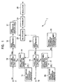
- Fig. 1 is a block diagram illustrating an information signal output apparatus according to an embodiment of the present invention.
- the information signal output apparatus of this embodiment may be used in, for example, a broadcast station, to generate and output broadcast signals consisting of a video signal and an audio signal.
- the information signal output apparatus may be used in a content provider as a so-called "authoring tool" for creating recording media, such as DVDs, on which content consisting of a video signal and an audio signal, such as movies, are recorded.
- an information signal output authoring) apparatus 1 of this embodiment has an input terminal 11 for video signals and an input terminal 18 for audio signals.
- additional information for copyright protection additional information containing copying control information is superimposed on a supplied video signal and a supplied audio signal as digital watermark information, and the resulting signals are then output.
- the information signal output apparatus (hereinafter simply referred to as the "output apparatus") 1 includes, as shown in Fig. 1, the digital-video-signal input terminal 11, and a video digital-watermark-information superimposition unit 12 (hereinafter referred to as the "video WM superimposition unit” 12).
- WM stands for digital watermark information (digital watermark), and the same applies to the following description in the specification.
- the output apparatus 1 also includes a video copying-control-information generator 13, a video additional-information forming unit 14, a relating-information generator 15, a video compression unit 16, a CGMS-information addition unit 17, the digital-audio-signal input terminal 18, an audio digital-watermark superimposition unit (hereinafter referred to as the "audio WM superimposition unit") 19, an audio copying-control-information generator 20, an audio additional-information forming unit 21, an audio compression unit 22, a multiplexer 23, a scrambler (encryption unit) 24, and a modulator 25.
- a video copying-control-information generator 13 a video additional-information forming unit 14
- a relating-information generator 15
- a video compression unit 16 a CGMS-information addition unit 17
- the digital-audio-signal input terminal 18 an audio digital-watermark superimposition unit (hereinafter referred to as the "audio WM superimposition unit") 19
- an audio copying-control-information generator 20 an audio additional-information forming unit
- a video signal Vd supplied via the input terminal 11 is supplied to the video WM superimposition unit 12. Meanwhile, the video copying-control-information generator 13 generates copying control information CV to be superimposed on the video signal Vd which has been supplied to the output apparatus 1, and supplies it to the video-signal additional-information forming unit 14.
- the video copying-control-information generator 13 is able to generate two-bit copying control information CV corresponding to the following four copying control states.
- the control state is 1, "Copying is allowed (Copy Free)", the control information CV indicating "00" is generated.
- the control state is 2, “Copying is allowed for only one generation (Copy Once)", the control information CV indicating "10" is generated.
- the control state is 3, “Copying is prohibited for further generations (No More Copies)", the control information CV indicating "01” is generated.
- the control state is 4, “Copying is absolutely prohibited (Never Copy)", the control information CV indicating "11” is generated.
- a controller (not shown) of the output apparatus 1 determines which copying control information is to be generated according to the corresponding control state in the video copying-control-information generator 13 in response to an instruction input from an operator (user) of this output apparatus 1 through, for example, a keyboard provided for the output apparatus 1.
- the video copying-control-information generator 13 generates "00" when the video signal Vd and the audio signal Au supplied to this output apparatus 1 correspond to "copying allowed (Copy Free)", and generates "11" when the video signal Vd and the audio signal Au correspond to "copying is absolutely prohibited (Never Copy)”.
- the relating-information generator 15 is formed of a random-number generator.
- the relating-information generator 15 When the video signal Vd and the audio signal Au are received and processed, the relating-information generator 15 generates a random number and supplies it to the video additional-information forming unit 14 and the audio additional-information forming unit 21 as the relating information for the additional information, thereby making it possible to superimpose the relating information RS, as well as the additional information, on the video signal Vd and the audio signal Au as the digital watermark information.
- the video additional-information forming unit 14 forms additional information to be superimposed on the video signal Vd based on the copying control information output from the video copying-control-information generator 13 and the relating information RS output from the relating-information generator 15.
- Fig. 2 illustrates video additional information FV to be formed in the video additional-information forming unit 14 of the output apparatus 1 of this embodiment.
- the video additional-information forming unit 14 forms, as shown in Fig. 2, eight-bit video additional information FV containing the copying control information CV and the relating information RS, and supplies the video additional information FV to the video WM superimposition unit 12. It should be noted that the last two bits of the remaining portion of the video additional information FV are unused in this embodiment.
- the supplementary information may be inserted into the last two bits of the video additional information FV.
- various types of information may be inserted into the video additional information FV.
- the eight-bit video additional information FV formed in the video additional-information forming unit 14 is supplied to the video WM superimposition unit 12.
- the video WM superimposition unit 12 performs spread spectrum processing on the video additional information FV by using a PN (Pseudorandom Noise)-sequence code (hereinafter referred to as the "PN code"), thereby forming digital watermark information.
- PN code Pseudorandom Noise
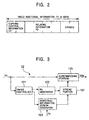
- Fig. 3 is a block diagram illustrating the video WM superimposition unit 12 of this embodiment.
- the video WM superimposition unit 12 includes a timing controller 121, a PN generator 122, an additional-information-stream generator 123, a spread spectrum portion (hereinafter simply referred to as the "spread portion) 124, and a WM superimposing portion (hereinafter simply referred to as the "superimposing portion”) 125.
- the video signal Vd from the input terminal 11 is supplied to the timing controller 121 and the superimposing portion 125 of the video WM superimposition unit 12.
- the timing controller 121 detects the vertical synchronizing timing and the horizontal synchronizing timing from the information contained in the video signal, and by using the detected timing as reference signals, the timing controller 121 generates various timing signals, such as a PN-code reset timing signal RE, a PN generating enable signal EN, and a PN clock signal PNCLK.
- the PN-code reset timing signal (reset signal) RE indicates the start timing of generating the PN code.
- the PN generating enable signal (enable signal) EN represents the interval in which the PN code for performing spread spectrum on the video additional information is generated.
- the PN clock signal PNCLK indicates, in this embodiment, the timing at which one chip of the PN code is generated, for example, one chip of the PN code is generated per pixel.
- the reset signal RE, the enable signal EN, and the PN clock signal PNCLK are supplied to the PN generator 122, and the enable signal EN and the PN clock signal PNCLK are supplied to the additional-information-stream generator 123.
- the PN generator 122 has multiple stages of shift registers, though they are not shown, and is formed of a few exclusive-OR circuits for computing appropriate tap outputs of the shift registers.
- the PN generator 122 generates the PN-code sequence PS according to the reset signal RE, the enable signal EN, and the clock signal PNCLK supplied from the timing generator 121.
- the PN generator 122 is reset by the reset signal RE in a cycle which synchronizes with the vertical synchronizing signal, such as in one frame cycle, and generates the PN-code sequence PS of a predetermined code pattern from the head.
- the PN generator 122 generates the PN-code sequence PS according to the clock signal PNCLK only when the PN code can be generated (enable state) by the enable signal EN.
- the additional-information-stream generator 123 generates video additional information stream FSV according to the clock signal PNCLK by switching, for example, the individual bits of the eight-bit video additional information at the timing of the enable signal EN. More specifically, by switching the individual bits of the video additional information at the timing of the enable signal EN, the video additional Information is output when the PN-code sequence PS is generated in the PN generator 122, thereby generating the video additional information stream FSV.
- the PN-code sequence PS from the PN generator 122 and the video additional information stream FSV from the additional-information-stream generator 123 are supplied to the spread portion 124.
- the spread-spectrum operation is performed on the video additional information stream FSV by the PN-code sequence PS, resulting in the video additional information FV, which is then supplied to the superimposing portion 125 as the digital watermark information.
- the superimposing portion 125 superimposes the digital watermark information indicating the video additional information FV output from the spread portion 124 on the video signal Vd, and supplies the video signal Vdw having the digital watermark information superimposed to the video compression unit 16.
- the video WM superimposition unit 12 forms the digital watermark information, which is a spread spectrum signal, and outputs the video signal having the digital watermark information superimposed.
- the video compression unit 16 compresses the video signal Vdw having the digital watermark information superimposed according to, for example, the moving picture experts group (MPEG) method, and supplies the compressed video signal to the CGMS-information addition unit 17.
- the CGMS-information addition unit 17 generates CGMS information in response to an instruction from a user of this output apparatus 1, and superimposes the CGMS information on the video signal Vdw.
- the CGMS information is two-bit copying control information, as stated above.
- the video signal Vdw having the CGMS information output from the CGMS-information addition unit 17 is supplied to the multiplexer 22. Not only the compressed video signal Vdw having the digital watermark information superimposed, but also a compressed audio signal having additional information superimposed as the digital watermark information is supplied to the multiplexer 22, which is described below.
- the audio signal Au which is associated with the video signal Vd supplied to the output apparatus 1, is also supplied to the output apparatus 1 via the input terminal 18, and is then supplied to the audio WM superimposition unit 19.
- the audio copying-control-information generator 20 generates copying control information CA to be superimposed on the audio signal Au supplied to the output apparatus 1, and supplies the control information CA to the audio additional-information forming unit 21.
- the audio copying-control-information generator 20 is able to generate two-bit copying control information CA corresponding to the following four copying control states.
- the control state is 1, "Copying is allowed (Copy Free)", the control information CA indicating "00" is generated.
- the control state is 2, “Copying is allowed for only one generation (Copy Once)", the control information CA indicating "10" is generated.
- the control state is 3, “Copying is prohibited for further generations (No More Copies)", the control information CA indicating "01” is generated.
- the control state is 4, “Copying is absolutely prohibited (Never Copy)", the control information CA indicating "11” is generated.
- a controller (not shown) of the output apparatus 1 determines which copying control information is to be generated according to the corresponding control state in response to an instruction input from an operator (user) of this output apparatus 1 through, for example, a keyboard provided for the output apparatus 1.
- the audio copying-control-information generator 20 generates "00" when the video signal Vd and the audio signal Au supplied to this output apparatus 1 correspond to the state "copying allowed (Copy Free)", and generates "10” when the video signal Vd and the audio signal Au correspond to the state "copying is allowed for only one generation (Copy Once)", and generates "11" when the video signal Vd and the audio signal Au correspond to the state "copying is absolutely prohibited (Never Copy)".
- the relating information RS from the relating-information generator 15 is also supplied to the audio additional-information forming unit 21.
- the audio additional-information forming unit 21 forms additional information to be superimposed on the audio signal Au based on the copying control information CA from the audio copying-control-information generator 20 and the relating information RS from the relating-information generator 15.
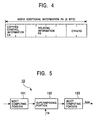
- Fig. 4 illustrates audio additional information FA to be formed in the audio additional-information forming unit 21.
- the audio additional-information forming unit 21 forms eight-bit audio additional information FA containing the copying control information CA and the relating information RS, and supplies the additional information FA to the audio WM superimposition unit 19.
- the remaining portion of the audio additional information FA is unused bits in this embodiment.
- information indicating, for example, the supply source of the audio signal may be inserted into the remaining portion of the audio additional information FA.
- the audio WM superimposition unit 19 performs a modified discrete cosine transform (hereinafter referred to as "MDCT") so as to determine an MDCT coefficient.
- MDCT modified discrete cosine transform
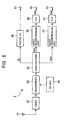
- Fig. 5 is a block diagram illustrating the audio WM superimposition unit 19 of this embodiment.
- the audio WM superimposition unit 19 is formed of an MDCT computing portion 191, a superimposing portion 192, and an inverse MDCT (IMDCT) computing portion 193.
- MDCT inverse MDCT
- the audio signal Au from the input terminal 18 is supplied to the MDCT computing portion 191 of the audio WM superimposition unit 19.
- MDCT computing portion 191 MDCT computation is performed on the audio signal Au to determine the MDCT coefficient.
- the determined MDCT coefficient is then supplied to the superimposing portion 192.
- the superimposing portion 192 codes the audio additional information FA by performing frequency shifting and inverse transforming so as to superimpose the audio additional information FA on the audio signal as the digital watermark information. Details of the method, used in this example, for forming the digital watermark information by using the MDCT and for superimposing it on the audio signal are discussed in Japanese Patent Application No. 11-076944.
- the output signal having the audio additional information FA superimposed as the digital watermark information output from the superimposing portion 192 is supplied to the IMDCT computing portion 193.
- the IMDCT computing portion 193 performs IMDCT computation, which is the reverse processing to the MDCT computation performed by the MDCT computing portion 191, on the output signal from the superimposing portion 192, thereby regenerating original audio signal as the output signal.
- the reproduced audio signal Auw is then supplied to the audio compression unit 22.
- the audio compression unit 22 compresses the audio signal Auw having the audio additional information FA superimposed according to, for example, the MPEG audio method, and supplies the compressed audio signal to the multiplexer 23. In this manner, the video signal Vdw and the audio signal Auw having the copying control information superimposed, which is used for copyright protection, as the digital watermark information are supplied to the multiplexer 23.
- the multiplexer 23 multiplexes the video signal Vdw with the audio signal Auw.
- the multiplexed signal of the video signal and the audio signal is then supplied to the scrambler 24.
- the scrambler 24 performs predetermined scrambling processing (encryption processing) on the supplied signal, and supplies the encrypted signal to the modulator 25.
- the modulator 25 modulates the signal output from the scrambler 24 and outputs the modulated signal.
- this output apparatus 1 is used as a broadcast apparatus in a broadcast station, an output processing unit is provided at the stage subsequent to the modulator 25, and in this output processing unit, a signal to be output is amplified and broadcast.
- this output apparatus 1 is used as an apparatus for recording the video signal and the audio signal on a recording medium, such as a DVD, a recording processing unit is provided at the stage subsequent to the modulator 25, and by this recording processing unit, the video signal and the audio signal are recorded on, for example, a recording medium.
- the output apparatus 1 of this embodiment superimposes the copying control information for copyright protection on both the video signal and the audio signal, which are associated with each other, as the digital watermark information, and outputs them.
- the video copying control information and the audio copying control information may indicate the same copying control state or different copying control states. Alternatively, only one of the video copying control information and the audio copying control information may be generated.
- the output apparatus 1 since the output apparatus 1 has both the video copying-control-information generator 13 and the audio copying-control-information generator 20, as shown in Fig. 1, the video copying control information and the audio copying control information can be flexibly generated.
- restricted-use control such as copying control
- Vd digital watermark information superimposed on the video signal
- Au digital watermark information superimposed on the audio signal Au
- Fig. 6 is a block diagram illustrating a set-top box (receiver) for receiving broadcast signals to be broadcast from a broadcasting apparatus to which the above-described information signal output apparatus shown in Fig. 1 is applied.
- broadcast radio waves transmitted from a broadcasting station or transmitted via an artificial satellite are received by an antenna 31 and are supplied to a tuner 32.
- the tuner 32 selects a target broadcast signal in response to an instruction input from a user of this set-top box 2 and supplies the selected signal to a descrambler 33.
- a conditional access unit (indicated as CA unit in Fig. 6) 34 is connected to, in this embodiment, a conditional access center (CA center) in a broadcasting station via, for example, a communication network. Then, communications are performed between the CA unit of the set-top box 2 and the CA center.
- a user to be charged who is a subscriber, is provided with an encryption key for decrypting the scrambled broadcast signal.
- the CA unit 34 supplies the provided encryption key to the descrambler 33.
- the descrambler 33 performs descrambling (decryption) processing based on the encryption key supplied from the CA unit 34, and supplies the decrypted (plain text) broadcast signal to a demultiplexer 35.
- the demultiplexer 35 demultiplexes the broadcast signal into a video signal Vdm, an audio signal Aum, and data Dt, such as the CGMS information.
- the data Dt such as the CGMS information added to, for example, the video signal Vd, is output via a digital interface (indicated by digital I/F in Fig. 6) and an output terminal 37 for digital signals.
- the video signal Vdm extracted from the broadcast signal is supplied to a video decompression unit 38 and is decompressed into the original baseband signal. Thereafter, the baseband signal is converted into an analog video signal Vda in a digital-to-analog (D/A) converter 39 and is output via an output terminal 40 for analog signals.
- the audio signal Aum extracted from the broadcast signal is supplied to an audio decompression unit 41 and is decompressed into the original baseband signal. Then, the baseband signal is converted into an analog audio signal Aua in a D/A converter 42, and is output via an output terminal 43 for analog signals.
- the set-top box 2 after both the video signal and the audio signal are decompressed, they are converted into analog signals and are output. Then, the analog signals are supplied to a recording apparatus. That is, in this set-top box 2, the video signal and the audio signal having the digital watermark information superimposed are output as they are.
- CGMS information added to the video signal or SCMS information added to the audio signal can be output as digital data separately from the video signal or the audio signal, and can be supplied to an apparatus to which the information is to be output.
- the CGMS information is output via the digital interface 36.
- this is not exclusive, and a digital video signal having CGMS information added and having digital watermark information superimposed and an audio signal having SCMS information added and having digital watermark information superimposed may be output via the digital interface 36.
- the type of apparatus to which the signals are to be output may be checked by the function of the digital interface 36. If the apparatus is a recording apparatus and if CGMS information or SCMS information indicate that copying is not allowed, the digital interface 36 may prevent the signals from being output. That is, the copyright protection may be performed appropriately based on CGMS information, SCMS information, and information of the apparatus to which the digital video signal and the digital audio signal are to be supplied.
- Fig. 7 is a block diagram illustrating an information signal recording apparatus (hereinafter simply referred to as the "recording apparatus") 3 incorporating the information signal processing apparatus of the present invention for receiving the analog video signal and the analog audio signal output from the above-described set-top box 2 and recording the signals on a recording medium 100.
- the recording medium 100 is a rewritable disc, such as a DVD.
- the recording apparatus 3 includes, as shown in Fig. 7, an input terminal 51 for analog video signals, an analog-to-digital (A/D) converter 52, a video WM detector 53, a video signal detector 54, a video compression unit 55, a checking unit 56, an input terminal 57 for analog audio signals, an A/D converter 58, an audio WM detector 59, an audio signal detector 60, an audio compression unit 61, a WM remark unit 62, a multiplexer 63, an writer 64, a determining unit 65, a warning information generator 66, a synthesizer 67, a D/A converter 68, an output terminal 69 for analog signals, an input terminal 70 for digital signals, and a digital interface 71.
- the analog video signal Vda output from the set-top box 2 shown in Fig. 6 is supplied to the A/D converter 52 via the input terminal 51 of the recording apparatus shown in Fig. 7.
- the A/D converter 52 converts the analog video signal Vda into a digital video signal Vdd and supplies it to the video WM detector 53 and the video signal detector 54.
- the video WM detector 53 supplies the video signal Vdd as it is to the video compression unit 55, and also detects the video additional information FV superimposed on the video signal Vdd as the digital watermark information, and supplies the detected video additional information FV to the checking unit 56 and the determining unit 65.
- the video signal Vdd supplied to the video compression unit 55 via the video WM detector 53 is compressed in the video compression unit 55 according to, for example, an MPEG method, and is then supplied to the multiplexer 63.
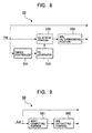
- Fig. 8 is a block diagram illustrating the video WM detector 53 of the recording apparatus 3 of this embodiment.
- the video WM detector 53 is formed of, as shown in Fig. 8, a timing controller 531, a PN generator 532, a de-spread portion 533, and a WM determining portion 534.
- the video signal Vdd output from the A/D converter 52 is supplied to the video compression unit 55 as it is via the video WM detector 53, and is also supplied to the timing generator 531 and the de-spread portion 533 of the video WM detector 53.
- the timing controller 531 of the video WM detector 53 is configured similarly to the timing controller 121 of the video WM superimposition unit 12 of the output apparatus 1 discussed with reference to Figs. 1 and 3.
- the timing controller 531 detects the vertical synchronizing timing and the horizontal synchronizing timing from the information contained in the video signal Vdd, and by using the detected timing as reference signals, it creates various timing signals, such as a PN-code reset timing signal RE, a PN generating enable signal EN, and a PN clock signal PNCLK.
- the timing controller 531 creates the reset signal RE, the enable signal EN, and the clock signal PNCLK for providing the same timing for the video signal Vdd as that when spread-spectrum operation is performed on the video additional information FV in the output apparatus 1, and supplies the timing signals to the PN generator 532.
- the PN generator 532 is configured similarly to the PN generator 122 of the video WM superimposition unit 12 shown in Fig. 3.
- the PN generator 532 generates the same PN-code sequence PS for the video signal Vdd, based on the reset signal RE, the enable signal EN, and the clock signal PNCLK, at the same timing as that when the spread-spectrum operation is performed on the video additional information FV.
- the PN-code sequence PS is then supplied to the de-spread portion 533.
- the de-spread portion 533 performs the de-spread spectrum operation by multiplying the video signal Vdd by the PN-code sequence PS from the PN generator 532 so as to extract the video additional information stream superimposed on the video signal Vdd as the digital watermark information.
- the de-spread portion 533 then supplies the video additional information stream to the digital watermark information determining portion (indicated by WM determining portion in Fig. 7) 534.
- the WM determining portion 534 integrates the video additional information stream output from the de-spread portion 533, and determines the original eight-bit video additional information FV. The determined video additional information FV is then supplied to the checking unit 56 and the determining unit 65. Simultaneously, in this embodiment, the WM determining portion 534 also detects the detection reliability of the video additional information FV, and supplies the corresponding information to the determining unit 65.
- the information of the detection reliability of the video additional information indicates whether the video additional information FV has been detected stably or unstably.
- Figs. 10 and 11 illustrate the detection reliability of the video additional information FV.
- the WM determining portion 534 integrates the information obtained from the de-spread portion 533. If the detection level of the integrated information gradually increases and the video additional information FV is always stably detected, as shown in Fig. 10, the detection reliability of the video additional information FV is high. The WM determining portion 534 thus determines that the video additional information FV has been detected correctly and precisely, and supplies it to the determining unit 65.
- the detection level fluctuates, as shown in Fig. 11, so that the video additional information FV is only occasionally (unstably) detected, the detection reliability of the video additional information FV is low. It is thus determined that the additional information FV has been erroneously detected, and the detection result is reported to the determining unit 65.
- the video signal detector 54 which receives the digital video signal Vdd from the A/D converter 52, monitors the level of the received signal and detects whether the video signal Vdd has been supplied, and reports the detection result to the determining unit 65.
- the video signal detector 54 when the video additional information FV is not detected, it can be checked whether the video additional information is not detected because it is not superimposed on the supplied video signal or the video additional information is not detected because the video signal is not supplied.
- the analog audio signal Aua output from the set-top box 2 shown in Fig. 6 is supplied to the A/D converter 58 via the input terminal 57 of the recording apparatus 3 shown in Fig. 7.
- the A/D converter 58 converts the analog audio signal Aua into a digital audio signal Aud and supplies it to the audio WM detector 59 and the audio signal detector 60.
- the audio WM detector 59 supplies the audio signal Aud to the audio compression unit 61, and also detects the audio additional information FA superimposed on the audio signal Aud as the digital watermark information, and supplies the detected audio additional information FA to the checking unit 56 and the determining unit 65.
- the audio signal Aud supplied to the audio compression unit 61 via the audio WM detector 59 is compressed in the audio compression unit 61 according to, for example, an MPEG audio method, and is then supplied to the digital watermark information remark unit (indicated by WM remark unit in Fig. 7) 62.
- the audio WM detector 59 detects the audio additional information FA superimposed on the audio signal Aud as the digital watermark information, as described below.
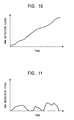
- Fig. 9 is a block diagram illustrating the audio WM detector 59 of the recording apparatus 3 of this embodiment.
- the audio WM detector 59 of this embodiment has, as shown in Fig. 9, an MDCT computing portion 591, and a digital-watermark-information extracting portion (indicated by WM extracting portion in Fig. 9) 592.
- the MDCT computing portion 591 of the audio WM detector 59 is configured similarly to the MDCT computing portion 191 of the audio WM superimposition unit 19 of the output apparatus 1 described with reference to Figs. 1 and 5.
- the MDCT computing portion 591 performs MDCT computation on the supplied audio signal Aud to determine the MDCT coefficient, and supplies the determined MDCT coefficient to the WM extracting portion 592.
- the WM extracting portion 592 extracts the digital watermark information from the MDCT coefficient corresponding to the portion on which the audio additional information FA is superimposed as the digital watermark information, and integrates the extracted digital watermark information, thereby extracting the audio additional information FA superimposed on the audio signal Aud as the digital watermark information.
- the WM extracting portion 592 then supplies the extracted audio additional information FA to the checking unit 56 and the determining unit 65.
- the WM extracting portion 592 of the audio WM detector 59 determines the detection reliability of the audio additional information FA superimposed on the audio signal Aud and supplies the determination result to the determining unit 65.
- the WM extracting portion 592 of the audio WM detector 59 makes a determination in the following manner. If the audio additional information FA superimposed on the audio signal Aud as the digital watermark information has been stably detected, as illustrated in Fig. 10, the detection reliability is determined to be high. If the audio additional information FA has been unstably detected, as shown in Fig. 11, the detection reliability is determined to be low.
- the audio signal detector 60 which receives the digital audio signal Aud from the A/D converter 58, monitors the level of the supplied audio signal, and detects whether the audio signal Aud has been supplied and reports the detection result to the determining unit 65.
- the audio signal detector 60 when the audio additional information FA is not detected, it can be checked whether the audio additional information FA is not detected because it is not superimposed on the supplied audio signal Aud or because the audio signal Aud is not supplied.
- the CGMS information extracted from the video signal in the demultiplexer 35 of the above-described set-top box 2 is output via the digital interface 36 and the digital-signal output interface 37.
- the CGMS information output from the set-top box 2 is received by the recording apparatus 3 via the digital-signal input terminal 70 and the digital interface 71 of the recording apparatus 3, and is supplied to the determining unit 65.
- the checking unit 56 which receives the video additional information FV (see Fig. 2) detected in the video WM detector 53 and the audio additional information FA (see Fig. 4) detected in the audio WM detector 59, checks the relating information RS of the video additional information FV against the relating information RS of the audio additional information FA. The checking unit 56 then supplies to the determining unit 65 the checking result indicating whether the relating information RS of the video additional information FV and that of the audio additional information FA are the same and both items of the additional information are related.
- the determining unit 65 then comprehensively determines whether the video signal Vda and the audio signal Aua supplied to the recording apparatus 3 can be copied on the disc 100 based on the following items of information: the checking result output from the checking unit 56, the video additional information FV and the information indicating the detection reliability output from the video WM detector 53, the audio additional information FA and the information indicating the detection reliability output from the audio WM detector 59, the information indicating the presence or the absence of the video signal from the video signal detector 54, and the information indicating the presence or the absence of the audio signal from the audio signal detector 60.
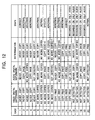
- Fig. 12 illustrates a determination logical table used in the determining unit 65 of the recording apparatus 3 of this embodiment.
- the determining unit 65 determines according to the logical table shown in Fig. 12 whether the video signal Vda and the audio signal Aua supplied to the recording apparatus 3 can be copied.
- case 8 shown in the logical table shown in Fig. 12 is a specific case.
- the output apparatus 1 shown in Fig. 1 when the video signal and the audio signal to be output are allowed to be copied for only one generation, "01” representing that "copying is prohibited for further generations (No More Copies)" is superimposed on the video signal as the copying control information, while “10” representing that "copying is allowed for only one generation (Copy Once)” is superimposed on the audio signal as the copying control information.
- the determining unit 65 determines that the video signal and the audio signal can be copied for only one generation.
- the determining unit 65 determines that the video signal and the audio signal can be copied for only one generation on the condition that the relating information RS of the additional information FV detected from the video signal coincides with the relating information RS of the additional information FA extracted from the audio signal.
- the determining unit 65 supplies a control signal to the WM remark unit 62 so as to give an instruction to overwrite the copying control information of the additional information FA superimposed as the digital watermark information, indicating that copying is allowed for only one generation, by the information indicating that copying is prohibited for further generations.
- the determining unit 65 also supplies a control signal to the writer 64 to perform a writing operation.
- the WM remark unit 62 overwrites (increments) the copying control information superimposed on the audio signal output from the audio compression unit 61, indicating that copying is allowed for only one generation, by the information indicating that copying is prohibited for further generations.
- the audio signal having the overwritten copying control information superimposed is supplied to the multiplexer 63.
- the multiplexer 63 then multiplexes the video signal from the video compression unit 55 with the audio signal from the WM remark unit 62, and supplies the multiplexed signal of the video signal and the audio signal to the writer 64.
- the writer 64 then records the multiplexed signal on the disc 100.
- both the copying control information superimposed on the video signal and that superimposed on the audio signal indicate that copying is prohibited from the first generation copy. Accordingly, in this case, the video signal and the audio signal copied on the disc 100 are not allowed to be copied any more on another recording medium.
- the reason for overwriting only the additional information superimposed on the audio signal is that it is easier to overwrite the additional information superimposed on the audio signal than that on the digital signal, and a minimal loss is incurred for the audio signal by overwriting the additional information.
- both the copying control information superimposed on the video signal and that on the audio signal indicate that copying is not allowed (copying is prohibited). This is a correct state.
- the determining unit 65 thus determines that copying of the video signal and the audio signal is not allowed (is prohibited), and controls the writer 64 not to copy the video signal and the audio signal.
- the determining unit 65 controls the warning information generator 66 to generate warning information (message) for reporting that copying is prohibited.
- This warning information is supplied to the synthesizer 67.
- the video signal Vdd is also supplied to the synthesizer 67 via the video WM detector 53.
- the synthesizer 67 combines the video signal Vdd with the warning information.
- the synthesized signal is then supplied to the D/A converter 68.
- the synthesized signal is converted into an analog signal in the D/A converter 68 and is further supplied to, for example, an external monitor receiver, via the analog-signal output terminal 69. It is thus possible to report to the user according to the display information that copying of the video signal and the audio signal is prohibited.
- both the copying control information superimposed on the video signal and that on the audio signal indicate that copying is not allowed (is prohibited) for further generations. This is a normal state.
- the determining unit 65 thus determines, as indicated by the two items of copying control information, that copying of the video signal and the audio signal is prohibited, and controls the writer 64 not to copy the video signal and the audio signal.
- both the copying control information superimposed on the video signal and that on the audio signal designate that copying is allowed. This is a correct state.
- the determining unit 65 thus determines, as indicated by the two items of copying control information, that the video signal and the audio signal can be copied (allowed), and controls the writer 64 to copy the video signal and the audio signal.
- Case 20 in Fig. 12 represents the state in which copying control information is not superimposed on the video signal or the audio signal, and is thus equivalent to the state in which copying is allowed. This is a normal state. Then, the determining unit 65 determines that the video signal and the audio signal can be copied, and controls the writer 64 to copy the video signal and the audio signal.
- Cases 2, 3, 4, 6, 9, 11, 12, and 13 in Fig. 12 designate that there is a discrepancy between the copying control information superimposed on the video signal and that on the audio signal. Since these cases are not normally generated, the determining unit 65 determines, based on the copying control information closer to a copy prohibiting state (tightly restricted copying control information), from the following three states, i.e., whether copying is not allowed (is prohibited), copying is allowed for only one generation, or copying is prohibited for further generations. According to this determination result, copying control of the video signal and the audio signal (copy-restricted control) is performed.
- a copy prohibiting state tightly restricted copying control information
- Such a control state is an abnormal state, as stated above.
- this abnormal state if the presence of the video signal and the audio signal is reliably detected and if the copying control information is stably detected from both the video signal and the audio signal, it may be considered that an attack was carried out to intentionally violate the copying restriction. In this case, the determining unit 65 may determine that copying is not allowed (is prohibited).
- the presence or the absence of the video signal and the audio signal is detected in the video signal detector 54 and the audio signal detector 60, respectively, and the detection result is supplied to the determining unit 65.
- the digital watermark information it is determined in the video WM detector 53 and the audio WM detector 59 whether the additional information superimposed on the video signal and that on the audio signal, respectively, have been stably detected, and the determination result is supplied to the determining unit 65.
- the copying control state can be determined taking into consideration the above-mentioned conditions.
- cases 5, 10, 15, 16, 17, 18, and 19 indicate that the additional information superimposed as the digital watermark information is not detected from the video signal or the audio signal.
- the copying control state is determined based on the copying control information detected from the video signal or the audio signal, and a determination is made whether copying can be performed.
- both case 5 and case 10 are equivalent to case 20, and thus, the determining unit 65 determines that copying is allowed both for the video signal and the audio signal, and controls the writer 64 to copy both signals.
- a detector for detecting the additional information in this embodiment, the video WM detector 53 or the audio WM detector 59, may have been operated erroneously.
- the determining unit 65 may determine that both the video signal and the audio signal can be copied.
- the determining unit 65 determines whether the digital watermark information has been erroneously detected. It is thus possible to remarkably improve the reliability of copying control using the digital watermark information.
- the presence or the absence of the video signal and that of the audio signal are detected by the video signal detector 54 and the audio signal detector 60, respectively. If additional information as digital watermark information has not been detected from one of the video signal or the audio signal because of the absence of the signal itself, and if additional information has been stably detected from the other signal, it can be verified that only one of the signals is present. In this case, copying control can be performed on the existing information signal based on the detected additional information.
- the additional information of only one of the video signal and the audio signal is detected, based on the additional information FV superimposed on the video signal, the additional information FA superimposed on the audio signal, the presence or the absence of the video signal, and the presence or the absence of the audio signal.
- the video signal and the audio signal may most probably have been illegally copied, and thus, it may be determined that copying is prohibited.
- the signals may most probably have been illegally copied, and thus, it may be unambiguously determined that copying is prohibited.
- the CGMS information output via the digital interface 36 and the output terminal 37 of the set-top box 2 is supplied to the determining unit 65 of the recording apparatus 3.
- the CGMS information received via the digital interface 71 may be used instead of the copying control information CA of the additional information FA added to the audio signal.
- copying-restricted control can be performed by using the copying control information CV of the additional information FV superimposed on the video signal, the copying control information CA of the additional information FA superimposed on the audio signal, and the CGMS information received via the digital interface 71.
- a random number is used as the relating information.
- specific checking information is not necessary, and another type of data may be used as long as data superimposed on the video signal and the audio signal as the digital watermark information can be protected from being read by the user.
- Data which can indicate the relationship between the video signal and the audio signal may be sent to verify the relating information of the video signal against that of the audio signal.
- relating information various types of information for relating the additional information added to the video signal and that to the audio signal may be used, for example, individual ID information of a program to be transmitted (video signal or audio signal) or an ID code of a copyright holder may be used.
- the detection threshold of the digital watermark information superimposed on the video signal and the audio signal may be decreased from a conventional threshold so as to improve the detection speed. That is, even with a reduced detection threshold, the reliability of the detected additional information can be maintained to a high level since both the additional information superimposed on the video signal and that on the audio signal are used.
- the threshold may be changed between when both the video signal and the audio signal are copied and when only one of the signals is copied. Accordingly, the detection reliability of the digital watermark information can be maintained.
- the video signal is not normally recorded singly, and thus, the recording of only the video signal may be prohibited.
- the additional information superimposed on the video signal may be differentiated from that on the audio signal.
- the transmission capacity of the additional information may be varied between the video signal and the audio signal, thereby making it possible to transmit various types of information.
- Fig. 13 is a block diagram illustrating an information signal playback apparatus (hereinafter simply referred to as the "playback apparatus") incorporating the information signal processing apparatus of the present invention for playing back and outputting the video signal and the audio signal recorded on a recording medium by using the information signal output apparatus shown in Fig. 1 as an authoring apparatus.
- the playback apparatus an information signal playback apparatus (hereinafter simply referred to as the "playback apparatus") incorporating the information signal processing apparatus of the present invention for playing back and outputting the video signal and the audio signal recorded on a recording medium by using the information signal output apparatus shown in Fig. 1 as an authoring apparatus.
- the recording medium 200 is, in this embodiment, a disc, such as a read-only DVD (DVD-ROM). That is, In this specification, the concept of the transmission of information signals encompasses not only the transmission of information signals by cable or radio, but also the recording of information signals on recording media and supplying them.
- the playback apparatus 4 of this embodiment is formed of, as illustrated in Fig. 13, a reader 81, a descrambler 82, a demultiplexer 83, a video decompression unit 84, a video WM detector 85, a video signal detector 86, a video synthesizer 87, a D/A converter 88, an output terminal 89 for analog video signals, a checking unit 90, an audio decompression unit 91, an audio WM detector 92, an audio signal detector 93, a D/A converter 94, an output terminal 95 for analog audio signals, a determining unit 96, a warning information generator 97, and a medium-type determining unit 98.
- a signal is read from the disc 200 by the reader 81 and is then supplied to the descrambler 82.
- the signal is descrambled (decrypted) and is supplied to the demultiplexer 83.
- the demultiplexer 83 demultiplexes the supplied signal into the video signal and the audio signal, and supplies the demultiplexed video signal to the video decompression unit 84 and supplies the demultiplexed audio signal to the audio decompression unit 91.
- the video decompression unit 84 decompresses the supplied video signal according to a predetermined method so as to reconstruct the original baseband video signal, and supplies it to the video WM detector 85 and the video signal detector 86.
- the audio decompression unit 91 decompresses the supplied audio signal according to a predetermined method so as to reconstruct the original baseband audio signal, and supplies it to the audio WM detector 92 and the audio signal detector 93.
- the video WM detector 85 is configured similarly to the video WM detector 53 of the recording apparatus 3 discussed with reference to Figs. 7 and 8.
- the video WM detector 85 supplies the video signal Vdd from the video decompression unit 84 to the synthesizer 87 as it is, and also detects the video additional information FV superimposed on the video signal Vdd as the digital watermark information and supplies it to the checking unit 90 and the determining unit 96.
- the video signal Vdd supplied to the synthesizer 87 via the video WM detector 85 is further supplied to the D/A converter 88.
- the video signal Vdd is converted into an analog video signal, and is then output via the output terminal 89.
- the output video signal is supplied to a monitor receiver.
- the video WM detector 85 performs inverse spread spectrum processing in a manner similar to the video WM detector 53 of the above-described recording apparatus 3 so as to detect the video additional information FV superimposed on the video signal Vdd as the digital watermark information, and supplies it to the checking unit 90 and the determining unit 96.
- the video WM detector 85 also detects the detection reliability of the video additional information FV in a manner similar to the video WM detector 53, and supplies the corresponding information to the determining unit 96.
- the video signal detector 86 which receives the video signal Vdd from the video decompression unit 84, monitors the level of the supplied video signal Vdd so as to detect the presence or the absence of the video signal Vdd, and supplies the detection result to the determining unit 96.
- the audio WM detector 92 is configured similarly to the audio WM detector 59 of the aforementioned recording apparatus 3 shown in Figs. 7 and 9.
- the audio WM detector 92 supplies the audio signal Aud from the audio decompression unit 91 to the D/A converter 94, and also detects the additional information FA superimposed on the audio signal Aud as the digital watermark information by performing the MDCT operation, and supplies the additional information FA to the checking unit 90 and the determining unit 96.
- the audio signal Aud supplied to the D/A converter 94 via the audio WM detector 92 is converted into an analog audio signal and is output via the audio-signal output terminal 95.
- the audio signal is then supplied to, for example, a speaker provided for the monitor receiver.
- the audio WM detector 92 determines the detection reliability of the additional information FA superimposed on the audio signal Aud and supplies the detection result to the determining unit 96.
- the audio signal detector 93 which receives the digital audio signal Aud from the audio decompression unit 91, monitors the level of the supplied audio signal so as to detect the presence or the absence of the audio signal Aud, and reports the detection result to the determining unit 96.
- the medium-type determining unit 98 determines the medium type of the disc 200 from the supplied information, and supplies the corresponding information to the determining unit 96.
- the checking unit 90 Upon receiving the video additional information FV (see Fig. 2) detected in the video WM detector 85 and the audio additional information FA (see Fig. 4) detected in the audio WM detector 92, the checking unit 90 checks the relating information RS of the additional information FV with that of the additional information FA. The checking unit 90 then supplies to the determining unit 96 the checking result indicating whether both items of relating information RS are the same and whether both items of additional information FV and FA can be related to each other.
- the determining unit 96 comprehensively determines whether the video signal and the audio signal recorded on the disc 200 can be played back, based on the checking result from the checking unit 90, the video additional information FV from the video WM detector 85, the audio additional information FA from the audio WM detector 92, the signal indicating the presence or the absence of the video signal from the video signal detector 86, the signal indicating the presence or the absence of the audio signal from the audio signal detector 93, and the medium-type information from the medium-type determining unit 98.
- the determining unit 96 makes a determination according to the logical table shown in Fig. 12 whether the video signal and the audio signal recorded on the disc 200 can be played back or whether they should not be played back, i.e., whether the signals have been recorded legally or illegally.
- the determining unit 96 determines that the video signal and the audio signal recorded on the disc 200 have been legally recorded. In this case, the determining unit 96 controls the reader 81 to read and play back the video signal and the audio signal from the disc 200.
- case 8 is a specific case, and is determined to be a correct state.
- the determining unit 96 controls the reader 81 not to read or play back the video signal and the audio signal recorded on the disc 200.
- the determining unit 96 also controls the warning information generator 97 to generate information (message) indicating that one or both of the video signal and the audio signal may have been illegally copied and are thus prohibited from being played back, and supplies the information to the synthesizer 87. Accordingly, the corresponding message is displayed on the display screen of the monitor receiver so that it can be reported to the user.
- the user of the disc 200 can complain to the seller of the disc 200, thereby making it possible to prevent the content obtained by illegally copying the video signal and the audio signal from being distributed.
- the prohibiting of the playback operation as described above may be too harsh to honest users. Accordingly, instead of prohibiting the playback of the video signal and the audio signal, a message indicating that the video signal and the audio signal may have been illegally copied may be added to the video signal to be played back, and the synthesized message may then be displayed.
- the determination result of the logical table not only the determination result of the logical table, but also the determination result of the medium-type determining unit 98 may be used, and only when it is determined that the possibility that illegal copying has been conducted is higher, the playback operation may be prohibited.
- the disc 200 is found to be a DVD-RAM (rewritable DVD) from the medium type, and if one or both of the copying control information superimposed on the video signal and that on the audio signal read from the disc 200 indicate that copying is allowed for only one generation, the playback operation may be prohibited.
- the disc 200 is found to be a DVD-RAM from the medium type, and if one or both of the copying control information recorded on the video signal and that on the audio signal designate that copying is not allowed, the playback operation may be prohibited.
- the copying control information of the video signal and the audio signal should be overwritten by that indicating that copying is not allowed any more (No More Copies) when they are copied.
- a video signal and an audio signal which are allowed to be copied for only one generation are recorded on a DVD-RAM.
- the possibility that the video signal and the audio signal have been illegally copied is high.
- the medium type also counts for making the determination, and the playback operation is prohibited only when there is a high possibility that illegal copying has been conducted. It is thus possible to prevent the illegally copied content from being distributed without being harsh to the users of the video signals and the audio signals.
- the video signal and the audio signal played back from the playback apparatus 4 of this embodiment may be supplied to the recording apparatus 3 and copied on a recording medium, such as a disc.
- copying control copying-restricted control
- a digital interface may be provided for the playback apparatus 4, and via this interface, the determination result of the medium-type determining unit 98 may be supplied to the determining unit 65 of the recording apparatus 3 via the digital interface 71.
- copying control can be performed by taking into consideration the type of recording medium of the generation source of the video signal and the audio signal loaded in the playback apparatus 4.
- the disc 200 is a DVD-RAM, and if one or both of the copying control information superimposed on the video signal read from the disc 200 and that on the audio signal read from the disc 200 indicate that copying is allowed for only one generation, copying is prohibited in the recording apparatus 3.
- the disc 200 is a DVD-RAM, and if one or both of the copying control information superimposed on the video signal read from the disc 200 and that on the audio signal read from the disc 200 represent that copying is not allowed, copying is prohibited in the recording apparatus 3.
- the copying control information of the video additional information FV detected from the video WM detector 85 and that of the audio additional information FA detected from the audio WM detector 92 correspond to one of the cases 5, 10, 15, 16, 17, 18, and 19, as shown in Fig. 12, i.e., if one of the copying control information is not detected, it is determined that the playback operation is performed in this embodiment.
- the medium type may be considered, and if there is a high possibility that the video signal and the audio signal have been illegally copied, as discussed above, the playback operation may be prohibited. It is thus possible to prevent the illegally copied content from being widely distributed.
- the playback apparatus 4 it is possible to accurately determine whether the additional information has been detected correctly or erroneously, by considering the presence or the absence of the video signal and the audio signal and the detection reliability of the additional information. Based on the correctly detected additional information, playback control can be performed.
- the playback operation may be unambiguously prohibited.
- highly reliable playback control can be performed by utilizing various items of information, such as the additional information superimposed on the video signal, its detection reliability, the additional information superimposed on the audio signal, its detection reliability, the presence or the absence of the video signal and the audio signal, the relating information of the additional information, and the medium type.
- the video WM detector 85, the video signal detector 86, the checking unit 90, the audio WM detector 92, the audio signal detector 93, the determining unit 96, and the warning information generator 97 provided for the playback apparatus 4 of this embodiment may be provided for the set-top box 2 shown in Fig. 6. This enables the set-top box 2 to perform output control of the video signal and the audio signal, as in the playback apparatus 4.
- the additional information as the digital watermark information is detected from the baseband video signal, thereby enhancing the simplicity of the circuit and avoiding the above-described danger in the format conversion (system conversion).
- the video additional information FV and the audio additional information FA each have a total of eight bits consisting of the copying control information (two bits), the relating information (four bits), and others (two bits).
- the additional information is not restricted to this format.
- only the audio signal may be desirably recorded on, for example, an MD. Accordingly, additional information for copyright protection may be added to only the audio signal, and in the MD recording/playback apparatus (MD apparatus), copyright protection for the audio signal may be performed based on the additional information for the audio signal.
- MD apparatus MD recording/playback apparatus
- additional information is added to a video signal and an audio signal in the following manner.
- the additional information used for copyright protection for both the video signal and the audio signal which may be used in a recording or a recording/playback apparatus, such as a DVD or a VCR, can be distinguished from the additional information used for copyright protection for each of the video signal and the audio signal, separately.
- Figs. 14, 15A, and 15B illustrate other examples of the additional information to be added to information signals, such as a video signal and an audio signal.
- the additional information has 16 bits, and contains two slots for additional information used for copyright protection of both the video signal and the audio signal and for additional information used for copyright protection of only one of the signals.
- Fig. 14 illustrates an example of the audio additional information.
- the additional information for copyright protection of both the video signal and the audio signal has two bits, i.e., bit 0 and bit 1, and the information for copyright protection only of the audio signal has four bits, i.e., from bit 2 to bit 5.
- the above-mentioned two types of additional information have been positioned in advance, namely, slots have been assigned to the additional information.
- Figs. 15A and 15B illustrate examples of audio additional information in which the additional information for copyright protection of both video signal and audio signal is distinguished from that only of the audio signal by the use of a header.
- header 1 is added, as shown in Fig. 15A, to the additional information for copyright protection of both the video signal and the audio signal
- header 2 is added, as shown in Fig. 15B, to the information for copyright protection of only the audio signal.
- the audio additional information has been discussed by way of example. The same applies to the video additional information.
- the length (bit length) of the additional information is predetermined, and the predetermined length of the additional information is repeatedly superimposed on the video signal and the audio signal as digital watermark information.
- information is not limited to the above items.
- the additional information superimposed on the video signal and that on the audio information may be used, or the relating information may also be used in addition to the above-mentioned items of information.
- the additional information superimposed on the video signal, its detection reliability, the additional information superimposed on the audio signal, and its detection reliability may be used, or the relating information may also be added in addition to the above-mentioned items of information.
- the additional information superimposed on the video signal, the additional information superimposed on the audio signal, and the presence or the absence of the video signal and the audio signal may be employed.
- the additional information superimposed on the video signal, its detection reliability, the additional information superimposed on the audio signal, its detection reliability, and the presence or the absence of the video signal and the audio signal may be employed. That is, copyright protection may be performed by using a required number of items of information.
- the presence or the absence of the video signal and the audio signal is determined by detecting the signal levels.
- a switch may be disposed which is turned on when connection cables are connected to the analog-video input terminal 51 and to the analog-audio input terminal 57 and which is turned off when the connection cables are not connected thereto.
- the presence or the absence of the video signal and the audio signal can be mechanically detected.
- the state of the switch is reported to the determining unit 65. Accordingly, when, for example, a copying operation is attempted even though only the connection cable for the video signal is connected to the recording apparatus 3 and the connection cable for the audio signal is not connected thereto, the determining unit 65 can determine that the signals are to be illegally copied, and prohibits the copying operation.
- a switch similar to that discussed above may be provided for the analog-video output terminal 89 and the analog-audio output terminal 95 of the playback apparatus 4 described with reference to Fig. 13, and the state of the switch may be reported to the determining unit 96.
- the determining unit 96 can determine that the signals are to be illegally copied, and prohibits the copying operation. The same applies to the set-top box 2 shown in Fig. 6.
- connection cable for the audio signal is connected in case 15 shown in Fig. 12, it may be determined that copying is prohibited.
- the information signal output apparatus shown in Fig. 1 may be used as a broadcasting apparatus in a broadcasting station, or a computer provided with a communication function, such as a server, or an authoring tool for creating recording media used by content providers.
- the playback apparatus 4 shown in Fig. 13 may be used for a receiving apparatus, such as a set-top box, and various types of output apparatuses for outputting video signals and audio signals, such as personal computers.
- a playback function may be provided for the recording apparatus 3 shown in Fig. 7, in which case, a resulting apparatus may be used as a recording/playback apparatus.
- the recording apparatus 3 shown in Fig. 7 may be combined with the playback apparatus 4 shown in Fig. 13, thereby forming a recording/playback apparatus.
- digital watermark information to be superimposed on the video signal is generated by using the spread spectrum operation, while digital watermark information to be superimposed on the audio signal is generated by using the MDCT and IMDCT operations.
- digital watermark techniques are not restricted to the above methods. Other types of digital watermark techniques may be used.
- the video additional information and the audio additional information are superimposed on the video signal and the audio signal, respectively, as digital watermark information.
- additional information other than digital watermark information may be used to perform copyright protection.
- CGMS information may be used for the video signal
- SCMS information may be used for the audio signal.
- copying control, playback control, and output control are performed as copyright protection.
- the copyright protection is not limited to the above types of control operations.
- the apparatus number which has conducted the illegal copying operation may be added to the video signal or the audio signal, and may suitably be displayed, thereby making it possible to trace the illegal user.
- the ID code of the copyright holder may be added to the video signal and the audio signal as the additional information, and if there is a discrepancy in the additional information between the video signal and the audio signal, the corresponding information (message) may be displayed and reported to the user.
- the video signal and the audio signal are used as targets of copyright protection.
- the present invention may be used when simultaneously transmitting various other types of information signals, such as a combination of computer data, for example, text data or program data, and a video signal, or a combination of computer data and an audio signal.
Landscapes
- Engineering & Computer Science (AREA)
- Multimedia (AREA)
- Signal Processing (AREA)
- Computer Security & Cryptography (AREA)
- Signal Processing For Digital Recording And Reproducing (AREA)
- Television Signal Processing For Recording (AREA)
- Storage Device Security (AREA)
- Television Systems (AREA)
- Editing Of Facsimile Originals (AREA)
- Signal Processing Not Specific To The Method Of Recording And Reproducing (AREA)
Applications Claiming Priority (2)
| Application Number | Priority Date | Filing Date | Title |
|---|---|---|---|
| JP20292799 | 1999-07-16 | ||
| JP11202927A JP2001036723A (ja) | 1999-07-16 | 1999-07-16 | 著作権保護方法、情報信号伝送システム、情報信号出力装置、情報信号受信装置および情報信号記録媒体 |
Publications (2)
| Publication Number | Publication Date |
|---|---|
| EP1069773A2 true EP1069773A2 (de) | 2001-01-17 |
| EP1069773A3 EP1069773A3 (de) | 2006-01-04 |
Family
ID=16465473
Family Applications (1)
| Application Number | Title | Priority Date | Filing Date |
|---|---|---|---|
| EP00305978A Withdrawn EP1069773A3 (de) | 1999-07-16 | 2000-07-14 | Kopierschutzverfahren, Informationssignalbearbeitungssystem, Informationssignalausgabeanlage, Informationssignalbearbeitungsanlage, Informationssignalausgabeverfahren, Informationssignalbearbeitungsverfahren, und Informationssignalaufnahmemedium |
Country Status (3)
| Country | Link |
|---|---|
| US (1) | US6850619B1 (de) |
| EP (1) | EP1069773A3 (de) |
| JP (1) | JP2001036723A (de) |
Cited By (2)
| Publication number | Priority date | Publication date | Assignee | Title |
|---|---|---|---|---|
| WO2005125214A3 (en) * | 2004-06-14 | 2006-03-30 | Rok Productions Ltd | Media player |
| WO2006089932A1 (en) * | 2005-02-25 | 2006-08-31 | Rok Productions Limited | Media player |
Families Citing this family (38)
| Publication number | Priority date | Publication date | Assignee | Title |
|---|---|---|---|---|
| EP1079372A4 (de) * | 1999-03-03 | 2006-02-15 | Sony Corp | Vorrichtung und verfahren zur aufzeichnung und wiedergabe |
| JP2001045448A (ja) * | 1999-07-30 | 2001-02-16 | Nec Corp | ディジタルtv放送における映像データ同期方式 |
| US7366907B1 (en) * | 1999-10-29 | 2008-04-29 | Sony Corporation | Information processing device and method and program storage medium |
| US7805764B1 (en) * | 2000-03-31 | 2010-09-28 | Doug Carson & Associates, Inc. | Sequencing data blocks to provide hidden data on a recording medium |
| TW517230B (en) * | 2000-10-06 | 2003-01-11 | Pioneer Corp | Information recording and reproducing apparatus, information reproducing method, recording medium, information recording medium in which recording control program is stored, information recording and reproducing control program |
| JP4470312B2 (ja) * | 2000-10-10 | 2010-06-02 | ソニー株式会社 | サーバ装置、再生装置、データ配信方法、データ再生方法、記憶媒体 |
| WO2002035747A2 (en) * | 2000-10-20 | 2002-05-02 | Koninklijke Philips Electronics N.V. | Rendering device and arrangement |
| JP4029569B2 (ja) * | 2000-12-13 | 2008-01-09 | 株式会社日立製作所 | ディジタル情報記録再生装置、記録装置、受信装置および送信装置 |
| US6996248B2 (en) * | 2001-06-13 | 2006-02-07 | Qualcomm, Incorporated | Apparatus and method for watermarking a digital image |
| JP3832289B2 (ja) * | 2001-08-20 | 2006-10-11 | ソニー株式会社 | 情報記録装置、ビデオ信号出力装置、ストリーム出力方法、プログラム、記録媒体、およびデータ構造 |
| CN100380493C (zh) * | 2001-09-05 | 2008-04-09 | 皇家飞利浦电子股份有限公司 | 用于直接流数字信号的坚韧水印 |
| JP3746230B2 (ja) * | 2001-09-29 | 2006-02-15 | 株式会社東芝 | レコーディング装置、コピー制御方法及びプログラム |
| US6944771B2 (en) * | 2001-12-20 | 2005-09-13 | Koninklijke Philips Electronics N.V. | Method and apparatus for overcoming a watermark security system |
| JP2003209789A (ja) * | 2002-01-10 | 2003-07-25 | Sony Corp | データ再生装置 |
| US20030156717A1 (en) * | 2002-02-21 | 2003-08-21 | Koninklijke Philips Electronics N.V. | Copy-protection by preserving copy-control signals |
| JP3782369B2 (ja) * | 2002-04-05 | 2006-06-07 | 株式会社日立製作所 | ストレージ装置、コンテンツ配信システム及びコンテンツの配信方法 |
| JP3521082B2 (ja) * | 2002-05-15 | 2004-04-19 | シャープ株式会社 | コンテンツ処理制限方法、およびコンテンツ編集装置 |
| CN100385903C (zh) * | 2002-06-24 | 2008-04-30 | 皇家飞利浦电子股份有限公司 | 视频中的实时签名嵌置 |
| US7315622B2 (en) * | 2002-06-27 | 2008-01-01 | Nxp B.V. | Robust method for achieving audio/video synchronization in MPEG decoders in personal video recording applications |
| JP3765413B2 (ja) * | 2002-07-12 | 2006-04-12 | ソニー株式会社 | 情報符号化装置および方法、情報復号装置および方法、記録媒体、並びにプログラム |
| JP2004139646A (ja) * | 2002-10-16 | 2004-05-13 | Kenwood Corp | データ記録装置、データ再生装置、データ出力装置及び配信システム |
| JP4001280B2 (ja) * | 2002-10-22 | 2007-10-31 | インターナショナル・ビジネス・マシーンズ・コーポレーション | 記憶装置、記憶装置を制御するプログラム、記憶装置の制御方法、及び記録媒体 |
| JP4214454B2 (ja) | 2002-12-13 | 2009-01-28 | ソニー株式会社 | 映像信号処理システム、映像信号処理装置および方法、記録媒体、並びにプログラム |
| US7162146B2 (en) * | 2003-02-07 | 2007-01-09 | Warner Bros. Entertainment Inc. | System and method for the assertion and identification of rights information in an analog video signal |
| US20040252973A1 (en) * | 2003-06-10 | 2004-12-16 | Samsung Electronics Co., Ltd. | System and method for audio/video data copy protection |
| US7460684B2 (en) * | 2003-06-13 | 2008-12-02 | Nielsen Media Research, Inc. | Method and apparatus for embedding watermarks |
| US20070088954A1 (en) * | 2003-09-30 | 2007-04-19 | Kabushiki Kaisha Kenwood | Digital watermark information adding device, data reproduction device and data recording device |
| US7454019B2 (en) * | 2003-12-05 | 2008-11-18 | Motion Picture Association Of America | System and method for controlling display of copy-never content |
| MX2007000076A (es) * | 2004-07-02 | 2007-03-28 | Nielsen Media Res Inc | Metodos y aparatos para mezclar corrientes comprimidas de bits digitales. |
| JP2006311269A (ja) * | 2005-04-28 | 2006-11-09 | Toshiba Corp | テレビジョン放送受信装置及び受信方法 |
| US20060277609A1 (en) * | 2005-06-07 | 2006-12-07 | Marc Brandon | Method and apparatus for tracking pirated media |
| JP4630753B2 (ja) * | 2005-07-29 | 2011-02-09 | パナソニック株式会社 | 復号化装置 |
| US20070245397A1 (en) * | 2006-04-14 | 2007-10-18 | Portrait Displays, Inc. | System and method for uploading TV firmware |
| WO2008045950A2 (en) | 2006-10-11 | 2008-04-17 | Nielsen Media Research, Inc. | Methods and apparatus for embedding codes in compressed audio data streams |
| US8768713B2 (en) * | 2010-03-15 | 2014-07-01 | The Nielsen Company (Us), Llc | Set-top-box with integrated encoder/decoder for audience measurement |
| US9323902B2 (en) * | 2011-12-13 | 2016-04-26 | Verance Corporation | Conditional access using embedded watermarks |
| US9924451B2 (en) * | 2015-12-02 | 2018-03-20 | Motorola Solutions, Inc. | Systems and methods for communicating half-rate encoded voice frames |
| CN114969428B (zh) * | 2022-07-27 | 2022-12-16 | 深圳市海美迪科技股份有限公司 | 一种基于大数据的音视频智能监管系统及方法 |
Family Cites Families (9)
| Publication number | Priority date | Publication date | Assignee | Title |
|---|---|---|---|---|
| US5315448A (en) * | 1993-03-18 | 1994-05-24 | Macrovision Corporation | Copy protection for hybrid digital video tape recording and unprotected source material |
| US5659613A (en) * | 1994-06-29 | 1997-08-19 | Macrovision Corporation | Method and apparatus for copy protection for various recording media using a video finger print |
| JP3901268B2 (ja) * | 1997-01-23 | 2007-04-04 | ソニー株式会社 | 情報信号出力制御装置、情報信号出力制御方法、情報信号複製防止装置および情報信号複製防止方法 |
| JP4038851B2 (ja) * | 1997-12-10 | 2008-01-30 | ソニー株式会社 | 再生装置及び方法、記録媒体、並びに信号処理装置及び信号処理方法 |
| JPH11177924A (ja) * | 1997-12-10 | 1999-07-02 | Sony Corp | 信号再生装置、信号記録装置、信号記録システム、信号再生方法、並びに、信号記録方法 |
| US6332194B1 (en) * | 1998-06-05 | 2001-12-18 | Signafy, Inc. | Method for data preparation and watermark insertion |
| JP4208998B2 (ja) * | 1998-07-03 | 2009-01-14 | パイオニア株式会社 | 複製制限機能を備えた記録再生システム、記録装置および再生装置 |
| US6490355B1 (en) * | 1998-07-14 | 2002-12-03 | Koninklijke Philips Electronics N.V. | Method and apparatus for use of a time-dependent watermark for the purpose of copy protection |
| US6522769B1 (en) * | 1999-05-19 | 2003-02-18 | Digimarc Corporation | Reconfiguring a watermark detector |
-
1999
- 1999-07-16 JP JP11202927A patent/JP2001036723A/ja active Pending
-
2000
- 2000-07-14 EP EP00305978A patent/EP1069773A3/de not_active Withdrawn
- 2000-07-14 US US09/616,832 patent/US6850619B1/en not_active Expired - Fee Related
Cited By (2)
| Publication number | Priority date | Publication date | Assignee | Title |
|---|---|---|---|---|
| WO2005125214A3 (en) * | 2004-06-14 | 2006-03-30 | Rok Productions Ltd | Media player |
| WO2006089932A1 (en) * | 2005-02-25 | 2006-08-31 | Rok Productions Limited | Media player |
Also Published As
| Publication number | Publication date |
|---|---|
| JP2001036723A (ja) | 2001-02-09 |
| EP1069773A3 (de) | 2006-01-04 |
| US6850619B1 (en) | 2005-02-01 |
Similar Documents
| Publication | Publication Date | Title |
|---|---|---|
| US6850619B1 (en) | Copyright protection method, information signal processing system, information signal output apparatus, information signal processing apparatus, information signal output method, information signal processing method, and information signal recording medium | |
| US6571220B1 (en) | Copy generation management method, information signal reproducing method, information signal reproducing apparatus, and information signal recording apparatus | |
| US5963909A (en) | Multi-media copy management system | |
| US8307212B2 (en) | Steganographic techniques for securely delivering electronic digital rights management control information over insecure communication channels | |
| US6530021B1 (en) | Method and system for preventing unauthorized playback of broadcasted digital data streams | |
| US7240206B2 (en) | Information signal copy managing method, information signal recording method, information signal output apparatus, and recording medium | |
| EP1155569B1 (de) | Kontrolle des Kopierens eines Videosignals mittels Wasserzeichen und damit in Beziehung stehender Zusatzdaten | |
| EP1032205B1 (de) | Verfahren und Vorrichtung zur Einbindung und Erkennung von zusätzlicher Information | |
| EP1005040A1 (de) | Verfahren zum Urheberrechtsschutz eines Informationssignals, Verfahren und Vorrichtung zur Aufzeichnung eines Informationssignals, und Informationssignalausgabeverfahren und -Vorrichtung | |
| US7062068B2 (en) | Data processing apparatus, data processing method, and program | |
| US20020106192A1 (en) | Contents data, recording medium, recording method and device, reproducing method and device | |
| US20030115534A1 (en) | Signal processing method and apparatus, signal reproducing method and apparatus, and recording medium | |
| KR20040043740A (ko) | 디지털 방송 컨텐츠 저장 및 재생을 위한 제어 장치 | |
| JPH11353795A (ja) | 情報信号再生装置、情報信号出力装置、情報信号再生方法および情報信号出力方法 | |
| JP3991178B2 (ja) | 複製世代管理方法、情報信号記録装置、情報信号出力装置および情報信号再生装置 | |
| KR100592898B1 (ko) | 정보 출력 장치 및 정보 출력 방법, 정보 기록 장치 및정보 기록 방법, 정보 출력 기록 시스템 및 정보 출력기록 방법, 및 정보 기록 매체 | |
| JP2000333141A (ja) | 高精細度映像信号の著作権保護方法および装置、放送方式、受信装置、記録再生方法、記録再生装置、再生方法および再生装置 | |
| JP2000057686A (ja) | 情報信号複製制御方法、情報信号出力装置および情報信号記録装置 | |
| JP2000156641A (ja) | 付加情報重畳方法、情報信号複製制御方法、情報信号出力装置および情報信号記録装置 | |
| JP2000090569A (ja) | 情報信号の再生制限方法、情報信号記録再生装置、情報信号記録装置、情報信号再生装置および書き換え可能記録媒体 |
Legal Events
| Date | Code | Title | Description |
|---|---|---|---|
| PUAI | Public reference made under article 153(3) epc to a published international application that has entered the european phase |
Free format text: ORIGINAL CODE: 0009012 |
|
| AK | Designated contracting states |
Kind code of ref document: A2 Designated state(s): AT BE CH CY DE DK ES FI FR GB GR IE IT LI LU MC NL PT SE |
|
| AX | Request for extension of the european patent |
Free format text: AL;LT;LV;MK;RO;SI |
|
| PUAL | Search report despatched |
Free format text: ORIGINAL CODE: 0009013 |
|
| AK | Designated contracting states |
Kind code of ref document: A3 Designated state(s): AT BE CH CY DE DK ES FI FR GB GR IE IT LI LU MC NL PT SE |
|
| AX | Request for extension of the european patent |
Extension state: AL LT LV MK RO SI |
|
| AKX | Designation fees paid | ||
| REG | Reference to a national code |
Ref country code: DE Ref legal event code: 8566 |
|
| STAA | Information on the status of an ep patent application or granted ep patent |
Free format text: STATUS: THE APPLICATION IS DEEMED TO BE WITHDRAWN |
|
| 18D | Application deemed to be withdrawn |
Effective date: 20060705 |