EP1069658A1 - Verfahren und Vorrichtung zur aktiven, digitalen Temperaturkompensation eines Etalons in einem wellenlängenstabilisierten Laser - Google Patents
Verfahren und Vorrichtung zur aktiven, digitalen Temperaturkompensation eines Etalons in einem wellenlängenstabilisierten Laser Download PDFInfo
- Publication number
- EP1069658A1 EP1069658A1 EP00305579A EP00305579A EP1069658A1 EP 1069658 A1 EP1069658 A1 EP 1069658A1 EP 00305579 A EP00305579 A EP 00305579A EP 00305579 A EP00305579 A EP 00305579A EP 1069658 A1 EP1069658 A1 EP 1069658A1
- Authority
- EP
- European Patent Office
- Prior art keywords
- temperature
- laser
- value
- optical filter
- control signal
- Prior art date
- Legal status (The legal status is an assumption and is not a legal conclusion. Google has not performed a legal analysis and makes no representation as to the accuracy of the status listed.)
- Withdrawn
Links
- BJQHLKABXJIVAM-UHFFFAOYSA-N bis(2-ethylhexyl) phthalate Chemical compound CCCCC(CC)COC(=O)C1=CC=CC=C1C(=O)OCC(CC)CCCC BJQHLKABXJIVAM-UHFFFAOYSA-N 0.000 title claims abstract description 73
- 238000000034 method Methods 0.000 title claims abstract description 34
- 230000003287 optical effect Effects 0.000 claims abstract description 34
- 230000008859 change Effects 0.000 claims abstract description 23
- 230000004044 response Effects 0.000 claims abstract description 14
- 238000004364 calculation method Methods 0.000 claims description 4
- VYPSYNLAJGMNEJ-UHFFFAOYSA-N Silicium dioxide Chemical compound O=[Si]=O VYPSYNLAJGMNEJ-UHFFFAOYSA-N 0.000 claims description 2
- 230000002431 foraging effect Effects 0.000 claims 2
- 238000012544 monitoring process Methods 0.000 abstract description 3
- 239000000463 material Substances 0.000 description 5
- 230000005540 biological transmission Effects 0.000 description 4
- 239000007795 chemical reaction product Substances 0.000 description 4
- 230000000694 effects Effects 0.000 description 3
- 230000000087 stabilizing effect Effects 0.000 description 3
- 238000007792 addition Methods 0.000 description 2
- 238000013459 approach Methods 0.000 description 2
- 238000004891 communication Methods 0.000 description 2
- 238000010586 diagram Methods 0.000 description 2
- 238000010438 heat treatment Methods 0.000 description 2
- 239000013307 optical fiber Substances 0.000 description 2
- 230000010355 oscillation Effects 0.000 description 2
- 230000032683 aging Effects 0.000 description 1
- 230000006399 behavior Effects 0.000 description 1
- 230000003750 conditioning effect Effects 0.000 description 1
- 238000007796 conventional method Methods 0.000 description 1
- 238000001816 cooling Methods 0.000 description 1
- 238000012217 deletion Methods 0.000 description 1
- 230000037430 deletion Effects 0.000 description 1
- 230000001066 destructive effect Effects 0.000 description 1
- 238000005516 engineering process Methods 0.000 description 1
- 230000008713 feedback mechanism Effects 0.000 description 1
- 239000000835 fiber Substances 0.000 description 1
- 230000006870 function Effects 0.000 description 1
- 238000005259 measurement Methods 0.000 description 1
- 238000012986 modification Methods 0.000 description 1
- 230000004048 modification Effects 0.000 description 1
- 238000004806 packaging method and process Methods 0.000 description 1
- 230000006903 response to temperature Effects 0.000 description 1
- 238000001228 spectrum Methods 0.000 description 1
- 230000006641 stabilisation Effects 0.000 description 1
- 238000011105 stabilization Methods 0.000 description 1
- 238000006467 substitution reaction Methods 0.000 description 1
Images

Classifications
-
- H—ELECTRICITY
- H01—ELECTRIC ELEMENTS
- H01S—DEVICES USING THE PROCESS OF LIGHT AMPLIFICATION BY STIMULATED EMISSION OF RADIATION [LASER] TO AMPLIFY OR GENERATE LIGHT; DEVICES USING STIMULATED EMISSION OF ELECTROMAGNETIC RADIATION IN WAVE RANGES OTHER THAN OPTICAL
- H01S5/00—Semiconductor lasers
- H01S5/06—Arrangements for controlling the laser output parameters, e.g. by operating on the active medium
- H01S5/068—Stabilisation of laser output parameters
- H01S5/0683—Stabilisation of laser output parameters by monitoring the optical output parameters
- H01S5/0687—Stabilising the frequency of the laser
-
- H—ELECTRICITY
- H01—ELECTRIC ELEMENTS
- H01S—DEVICES USING THE PROCESS OF LIGHT AMPLIFICATION BY STIMULATED EMISSION OF RADIATION [LASER] TO AMPLIFY OR GENERATE LIGHT; DEVICES USING STIMULATED EMISSION OF ELECTROMAGNETIC RADIATION IN WAVE RANGES OTHER THAN OPTICAL
- H01S5/00—Semiconductor lasers
- H01S5/0014—Measuring characteristics or properties thereof
- H01S5/0021—Degradation or life time measurements
-
- H—ELECTRICITY
- H01—ELECTRIC ELEMENTS
- H01S—DEVICES USING THE PROCESS OF LIGHT AMPLIFICATION BY STIMULATED EMISSION OF RADIATION [LASER] TO AMPLIFY OR GENERATE LIGHT; DEVICES USING STIMULATED EMISSION OF ELECTROMAGNETIC RADIATION IN WAVE RANGES OTHER THAN OPTICAL
- H01S5/00—Semiconductor lasers
- H01S5/06—Arrangements for controlling the laser output parameters, e.g. by operating on the active medium
- H01S5/0617—Arrangements for controlling the laser output parameters, e.g. by operating on the active medium using memorised or pre-programmed laser characteristics
-
- H—ELECTRICITY
- H01—ELECTRIC ELEMENTS
- H01S—DEVICES USING THE PROCESS OF LIGHT AMPLIFICATION BY STIMULATED EMISSION OF RADIATION [LASER] TO AMPLIFY OR GENERATE LIGHT; DEVICES USING STIMULATED EMISSION OF ELECTROMAGNETIC RADIATION IN WAVE RANGES OTHER THAN OPTICAL
- H01S5/00—Semiconductor lasers
- H01S5/06—Arrangements for controlling the laser output parameters, e.g. by operating on the active medium
- H01S5/068—Stabilisation of laser output parameters
- H01S5/06804—Stabilisation of laser output parameters by monitoring an external parameter, e.g. temperature
-
- H—ELECTRICITY
- H01—ELECTRIC ELEMENTS
- H01S—DEVICES USING THE PROCESS OF LIGHT AMPLIFICATION BY STIMULATED EMISSION OF RADIATION [LASER] TO AMPLIFY OR GENERATE LIGHT; DEVICES USING STIMULATED EMISSION OF ELECTROMAGNETIC RADIATION IN WAVE RANGES OTHER THAN OPTICAL
- H01S5/00—Semiconductor lasers
- H01S5/06—Arrangements for controlling the laser output parameters, e.g. by operating on the active medium
- H01S5/068—Stabilisation of laser output parameters
- H01S5/0683—Stabilisation of laser output parameters by monitoring the optical output parameters
- H01S5/06837—Stabilising otherwise than by an applied electric field or current, e.g. by controlling the temperature
Definitions
- the present invention relates generally to tunable lasers and other tunable optical signal sources and more particularly to a method and system for compensating for a temperature induced shift in an etalon's Fabry-Perot output characteristics relative to a channel grid on which the laser wavelength lock is to be maintained.
- Optical fiber communications systems provide for low loss and very high information carrying capacity.
- the bandwidth of optical fiber may be utilized by transmitting many distinct channels simultaneously using different carrier wavelengths.
- the associated technology is called wavelength division multiplexing (WDM).
- WDM wavelength division multiplexing
- eight, sixteen or more different wavelengths are closely spaced to increase fiber transmission capacity.
- the wavelength bandwidth that any individual channel occupies depends on a number of factors, including the impressed information bandwidth, and margins to accommodate carrier frequency drift, carrier frequency uncertainty, and to reduce possible inter-channel cross-talk due to non-ideal filters.
- a laser generates light over rather broad bandwidths referred to as the laser gain curve.
- the only longitudinal-mode discrimination in conventional Fabry-Perot lasers is provided by the gain spectrum itself. Since the laser cavity is a type of Fabry-Perot interferometer, the energy output over the gain curve is not continuous but occurs at discrete, closely spaced frequencies. The output frequencies are based upon the number of discrete longitudinal modes that are supported by the laser cavity. The longitudinal modes will occur at wavelengths such that an integral number of half wavelengths equals the distance between the mirrors of the resonator in the laser.
- Laser oscillation can occur only at frequencies where the laser gain curve exceeds the losses in the optical path of the resonator.
- the broadened laser gain curve exceeds the cavity losses over a large frequency range, on the order of 8 to 10 GHz. As noted above, there will be a number of discrete, closely spaced modes oscillating within this range.
- DFB Distributed-feedback
- a grating integral to the laser structure limits the output to a single frequency.
- Another of the most common methods requires the use of a frequency selective external cavity/etalon in combination with such a laser device to detect the output wavelength at which the laser is operating and adjust the laser accordingly by varying the temperature of the laser, known as temperature tuning.
- temperature tuning a frequency selective external cavity/etalon in combination with such a laser device to detect the output wavelength at which the laser is operating and adjust the laser accordingly by varying the temperature of the laser, known as temperature tuning.
- temperature tuning varying the temperature of the laser
- Such a method allows for wavelength locking of a laser even in the event of changing ambient temperature conditions.
- the external cavity/etalon laser is most commonly applied to gas tube lasers but has also been applied for very narrow line width lasers such as those needed for laser gyro use.
- an etalon consists of a quartz glass plate with parallel surfaces that is placed in the laser resonator at a non-normal angle. Internal reflections give rise to interference effects which cause the etalon to behave as a frequency selective transmission filter, passing with minimum loss frequencies close to a transmission peak and rejecting by destructive interference other frequencies.
- the transmission peak of the etalon is set to coincide with a particular longitudinal mode resulting in single frequency operation of the laser.
- TEC Thermo-Electric Cooler
- DWDM dense wavelength division multiplexing
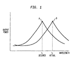
- temperature tuning of a laser's wavelength is accomplished by varying the laser chip temperature via the control current supplied to the Thermo-Electric Cooler (TEC) that the laser chip is mounted on within the laser package. As shown in Fig.
- a laser package will tune the laser chip to maintain the desired maximum output power at the desired wavelength ( ⁇ desired), illustrated by point A.
- ⁇ desired desired wavelength
- the temperature of the etalon will also change.
- the index of refraction of the material varies and more strongly, the etalon expands or contracts, changing the effective path lengths within the material and thereby changing the interference effects.
- the response curve of the etalon will also vary.
- the control system of the laser chip will temperature tune the laser chip based on the varied etalon response curve, causing the wavelength output to vary to a different wavelength ( ⁇ actual), illustrated by point B.
- This wavelength shift due to control system error and hysteresis can cause problems in the end system. Since the laser is initially set to deliver, to the end system in which the laser is mounted, a specified power and wavelength output, when the wavelength of the output varies it can cause disruption to the operation of the end-product system and possibly even damage the functionality of the end-product system.
- the present invention provides a unique method and apparatus for locking on an absolute wavelength of laser light by actively compensating for a change in temperature of an etalon optical filter.
- changes in etalon response characteristics due to temperature changes are compensated for by the addition (or subtraction) of an output voltage offset to the voltage control signal sent to the Thermo-Electric Cooler (TEC) within the laser package.
- TEC Thermo-Electric Cooler
- These calculations can be performed by conventional analog circuitry or by digital manipulation of analog signals by a microcontroller or similar digital signal processor.
- the voltage offset is calculated by monitoring the etalon temperature.
- the voltage offset value provides for active compensation of changes in the etalon temperature and effectively "readjusts" the output of the laser as if the etalon temperature itself had been readjusted back to its initial temperature.
- an absolute wavelength of laser light can be locked on by actively compensating for a change in temperature of the etalon optical filter.
- Fig. 2 illustrates in block diagram form a portion of a typical wavelength stabilized laser system 10. More specifically, Fig. 2 illustrates a control circuit for a temperature tuned laser system 10 that can actively compensate for temperature changes in an etalon in accordance with the present invention.
- a laser chip 12 is mounted on a Thermo-Electric Cooler (TEC) 52.
- TEC Thermo-Electric Cooler
- a submount (not shown) between the laser chip 12 and the TEC 52 can be used if desired for thermal expansion matching.
- the output of laser chip 12 can be adjusted by modifying the temperature of laser chip 12, as a laser chip will have an output directly related to its operating temperature.
- the output of the laser can be adjusted to the desired output level by changing the temperature of the laser chip.
- the temperature of laser chip 12 can be adjusted by varying the temperature of TEC 52.
- Controller 40 may include a programmable logic device, one example being a microprocessor. If a microprocessor is used, it may be any conventional general purpose single- or multi-chip microprocessor, or may be any conventional special purpose microprocessor such as a digital signal processor. Analog signal conditioning techniques may also be applied to the A/D and D/A signals.
- Controller 40 monitors and controls the output of laser chip 12 as follows.
- Laser chip 12 generates a laser output 11 and a backface output 13.
- the output 13 from laser chip 12 is input to an optical splitter 14 to split the output into two separate outputs 15, 25.
- the first output 15, hereinafter referred to as the reference path is input to a photodetector 16, as is known in the art, to convert the laser from an optical signal to an electrical signal.
- the converted electrical signal is input to an amplifier circuit 18, which may include for example operational amplifiers 20, 22 and feedback impedance 24.
- the output from amplifier circuit 18 is converted from an analog signal to a digital signal by analog to digital (A/D) converter 26 and input to controller 40.
- A/D analog to digital
- the second output 25, hereinafter referred to as the etalon path, is input to an etalon filter 30 as is known in the art.
- the output from the etalon filter 30 is input to a second photodetector 16a to convert the laser from an optical signal to an electrical signal.
- the converted electrical signal is input to an amplifier circuit 18a, which may include for example operational amplifiers 20a, 22a and feedback resistor 24a.
- the output from amplifier circuit 18a is converted from an analog signal to a digital signal by A/D converter 26a and input to controller 40.
- the temperature of the etalon filter 30 is monitored by a thermistor 32 and input to controller 40.
- the controller 40 uses the etalon path signal, i.e., the path that passes through the etalon 30, the reference path signal, i.e., the path that is output directly from the laser chip 12 without passing through the etalon filter 30, and the temperature measured by thermistor 32 to monitor the etalon 30 and laser chip 12 (unless a separate thermistor is also included for monitoring the laser chip as described below) to adjust the output 11 of laser chip 12 accordingly by causing TEC driver 50 to vary the temperature of TEC 52.
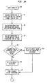
- Fig. 3A in step 100, the laser chip 12 is turned on.
- step 110 the temperature of the laser chip 12 is measured by thermistor 32 and input to controller 40.
- the laser chip 12 and etalon filter 30 are in such close proximity to each other that any temperature gradient between them is negligible. Therefore, the temperature of laser chip 12 and etalon filter 30 can be measured utilizing only one thermistor, such as thermistor 32.
- laser chip 12 and etalon filter 30 may be provided with their own thermistor if desired.
- Controller 40 can then reference a look-up table to determine the necessary temperature of the laser chip 12 to output the desired wavelength as predetermined by the end product system requirements.
- the values in the look-up table are defined during the calibration of laser chip 12 based on the response of laser chip 12 and can be stored, for example, in a memory of controller 40. Based on the temperature value determined from the look-up table, controller 40 will know the required temperature of laser chip 12, determined during calibration, to cause laser chip 12 to provide the desired output.
- the wavelength vs. temperature output of laser chip 12 may vary over time as laser chip 12 ages.
- the values in the look-up table may no longer be accurate.
- the look-up tables can be supplemented by controller 40, such as for example by a "learning" algorithm, by using historical statistical data to predict and adapt to variations in the laser chip 12 as it ages.
- step 120 the signals from the reference path and the etalon path are measured by controller 40. Controller 40 then subtracts the value of the etalon path signal from the value of the reference path signal and stores this as a Difference Value. It should be noted that compensation for laser aging can be performed in real time based on statistically predicted values for the Difference Value.
- step 130 the temperature of the etalon filter is measured by thermistor 32 and stored as an Initial Value. Controller 40 then calls an etalon temperature look-up table to determine the approximate etalon temperature for the desired etalon response curve. As previously noted, the temperature of the etalon determines the expansion of the material, which determines the effective path lengths light travels within the material and changes the interference effects.
- step 140 the Initial Value measured in step 130 is compared to the expected value from the look-up table. If the Initial Value is equal to the expected value, then in step 160 a variable called grid_offset is set to zero. If the Initial Value is not equal to the expected value, then in step 150 the value for grid-offset is adjusted accordingly, i.e., adjusted based on the difference between the Initial Value and the expected value obtained from the look-up table. It should be noted that the purpose of steps 140-150 is to allow the system to self-calibrate relative to the values stored in the look-up tables prior to any actual heating/cooling of the laser chip 12 via TEC 52, although it should be noted that laser chip 12 may self-heat at turn-on. Thus, for example, if the laser system 10 is mounted in an end-product system that has an elevated ambient temperature, the laser system 10 can immediately start to compensate for the elevated ambient temperature before any actual heating of the laser chip 12 is performed by TEC 52.
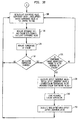
- step 170 the temperature of the etalon as measured by thermistor 32 is stored by controller 40.
- step 180 the Difference Value is recalculated to be the Difference Value + the value of grid_offset, and the new value for the Difference Value is output from controller 40 through D/A converter 42 to TEC driver 50.
- TEC driver 50 in response to the signal from controller 40, i.e., the value of the adjusted Difference Value, adjusts the temperature of TEC 52, which correspondingly adjusts the output of laser chip 12.
- step 190 the signals from the reference path and the etalon path are again measured by controller 40. Controller 40 then determines a new value for the Difference Value using the same calculation given with respect to step 120 above.
- step 200 the temperature of the etalon is again measured by thermistor 32.
- step 210 it is determined if the etalon temperature has changed since the previous measurement. If the etalon temperature has not changed, no compensation for a change in etalon temperature is necessary.
- the method returns to step 180, where a new value for the Difference Value is calculated by adding the value of the Difference Value as calculated in step 190 and the value of grid_offset.
- the new value calculated for the Difference Value is then output from controller 40 to TEC driver 50 which adjusts the temperature of TEC 52 accordingly.
- step 220 it is determined if the temperature change is significant enough to alter the response properties of the etalon based on the accuracy desired for the system. The higher the accuracy and resolution desired, the lower the value that would represent a significant change. Thus, for example, a temperature change of only 0.5° C might be considered significant enough in one system, while in other systems a temperature change of at least 1.5° C is necessary to be considered significant.
- the value at which a temperature change is considered significant is predetermined and may be stored by controller 40. If the temperature change is not considered significant enough, the method returns to step 180 where a new value for the Difference Value is calculated by adding the value of the Difference Value as calculated in step 190 and the value of grid_offset. The new value for the Difference Value is then output from controller 40 to TEC driver 50 which adjusts the temperature of TEC 52 accordingly.
- step 230 a value for an offset_increment_value is calculated.
- the value of the initial_offset_increment_value is predetermined based on the properties of the material being used for the etalon and its response to temperature changes.
- step 240 the value for the etalon temperature measured in step 200 is stored.
- step 250 a new value for grid_offset is determined by adding the value for offset_increment_value determined in step 230 to the previous value for grid_offset.
- the method returns to step 180, where a new value for Difference Value is calculated with the new value for grid_offset from step 250.
- the new value for the Difference Value is then output from controller 40 to TEC driver 50 which adjusts the temperature of TEC 52 accordingly.
- the temperature of the etalon is monitored and the value for grid_offset adjusted based on the temperature change of the etalon.
- the laser system 10 can then effectively compensate for changes in the etalon response due to a temperature change in the etalon by using the value obtained for grid_offset in the calculation of the Difference Value which is used to control the TEC 52.
- laser system 10 can effectively lock on to an absolute wavelength of laser light.
- the invention has been described as being implemented with a laser chip 12, it is to be understood that the invention is not so limited and may be used with any type of laser source as is known in the art, such as for example an array of lasers, a DFB laser, a distributed Bragg reflector (DBR) laser, a Fabry-Perot laser, etc. Additionally, the invention may be used with all temperature sensitive/wavelength sensitive elements, such as for example etalons, interference filters (lowpass, bandpass, and highpass), multiple grouping of filters (bandnotch), gratings, and the like.
Landscapes
- Physics & Mathematics (AREA)
- Condensed Matter Physics & Semiconductors (AREA)
- General Physics & Mathematics (AREA)
- Electromagnetism (AREA)
- Optics & Photonics (AREA)
- Semiconductor Lasers (AREA)
Applications Claiming Priority (2)
| Application Number | Priority Date | Filing Date | Title |
|---|---|---|---|
| US09/352,827 US6516010B1 (en) | 1999-07-13 | 1999-07-13 | Method and apparatus for active numeric temperature compensation of an etalon in a wavelength stabilized laser |
| US352827 | 1999-07-13 |
Publications (1)
| Publication Number | Publication Date |
|---|---|
| EP1069658A1 true EP1069658A1 (de) | 2001-01-17 |
Family
ID=23386673
Family Applications (1)
| Application Number | Title | Priority Date | Filing Date |
|---|---|---|---|
| EP00305579A Withdrawn EP1069658A1 (de) | 1999-07-13 | 2000-07-03 | Verfahren und Vorrichtung zur aktiven, digitalen Temperaturkompensation eines Etalons in einem wellenlängenstabilisierten Laser |
Country Status (5)
| Country | Link |
|---|---|
| US (2) | US6516010B1 (de) |
| EP (1) | EP1069658A1 (de) |
| JP (1) | JP2001044558A (de) |
| CN (1) | CN1280310A (de) |
| CA (1) | CA2313610A1 (de) |
Cited By (21)
| Publication number | Priority date | Publication date | Assignee | Title |
|---|---|---|---|---|
| EP1215832A3 (de) * | 2000-12-13 | 2003-08-27 | Nec Corporation | Optischer Sender mit variablen Wellenlänge und Ausgangsteuerung, und optisches Kommunikationssystem darauf |
| EP1345296A1 (de) * | 2002-03-16 | 2003-09-17 | Agilent Technologies, Inc. (a Delaware corporation) | System zur Leistungskontrol, Wellenlänge und Extinktionsratio in ioptischen Quellen und Rechnerprogram dafür |
| WO2003023463A3 (en) * | 2001-09-12 | 2003-11-13 | Honeywell Int Inc | Tunable optical filter |
| US6807208B2 (en) | 2001-08-22 | 2004-10-19 | The Furukawa Electric Co., Ltd. | Laser module |
| US6856633B2 (en) | 2001-06-07 | 2005-02-15 | The Furukawa Electric Co., Ltd. | Optical module, transmitter and WDM transmitting device |
| EP1571743A1 (de) * | 2004-03-01 | 2005-09-07 | Lucent Technologies Inc. | Verfahren und Gerät zur Wellenlängenstabilisierung eines Lasers mittels Temperaturkompensation. |
| US7106978B2 (en) | 2001-10-09 | 2006-09-12 | The Furukawa Electric Co., Ltd. | Optical module, optical transmission apparatus, WDM optical transmission device, and method for stabilizing laser wavelength |
| WO2006098022A1 (ja) * | 2005-03-16 | 2006-09-21 | Fujitsu Limited | 光波長安定化制御回路 |
| US7145165B2 (en) | 2001-09-12 | 2006-12-05 | Honeywell International Inc. | Tunable laser fluid sensor |
| US7470894B2 (en) | 2002-03-18 | 2008-12-30 | Honeywell International Inc. | Multi-substrate package assembly |
| US7586114B2 (en) | 2004-09-28 | 2009-09-08 | Honeywell International Inc. | Optical cavity system having an orthogonal input |
| US7649189B2 (en) | 2006-12-04 | 2010-01-19 | Honeywell International Inc. | CRDS mirror for normal incidence fiber optic coupling |
| US7656532B2 (en) | 2006-04-18 | 2010-02-02 | Honeywell International Inc. | Cavity ring-down spectrometer having mirror isolation |
| US7663756B2 (en) | 2008-07-21 | 2010-02-16 | Honeywell International Inc | Cavity enhanced photo acoustic gas sensor |
| US7864326B2 (en) | 2008-10-30 | 2011-01-04 | Honeywell International Inc. | Compact gas sensor using high reflectance terahertz mirror and related system and method |
| US7902534B2 (en) | 2004-09-28 | 2011-03-08 | Honeywell International Inc. | Cavity ring down system having a common input/output port |
| US8198590B2 (en) | 2008-10-30 | 2012-06-12 | Honeywell International Inc. | High reflectance terahertz mirror and related method |
| US8269972B2 (en) | 2010-06-29 | 2012-09-18 | Honeywell International Inc. | Beam intensity detection in a cavity ring down sensor |
| US8322191B2 (en) | 2010-06-30 | 2012-12-04 | Honeywell International Inc. | Enhanced cavity for a photoacoustic gas sensor |
| US8437000B2 (en) | 2010-06-29 | 2013-05-07 | Honeywell International Inc. | Multiple wavelength cavity ring down gas sensor |
| EP3471222A4 (de) * | 2016-06-08 | 2019-06-26 | Mitsubishi Electric Corporation | Laserlichtquellenvorrichtung |
Families Citing this family (60)
| Publication number | Priority date | Publication date | Assignee | Title |
|---|---|---|---|---|
| JP4255611B2 (ja) * | 2000-10-30 | 2009-04-15 | 富士通株式会社 | 光源装置及び光源装置の波長制御装置 |
| JP2002246683A (ja) * | 2001-02-15 | 2002-08-30 | Toshiba Corp | 光送信器及び光伝送システム |
| JP3737383B2 (ja) * | 2001-05-21 | 2006-01-18 | ユーディナデバイス株式会社 | 半導体レーザモジュール試験装置および半導体レーザモジュール試験方法 |
| US6822986B2 (en) | 2001-06-01 | 2004-11-23 | The Furakawa Electric Co., Ltd. | Method of controlling a wavelength of a semiconductor laser, optical module, optical transmitter, WDM optical transmission apparatus, and method of controlling a wavelength of an optical module |
| JP2003008138A (ja) * | 2001-06-13 | 2003-01-10 | Motorola Inc | レーザーダイオード制御装置 |
| JP4084006B2 (ja) * | 2001-06-27 | 2008-04-30 | 株式会社日立製作所 | 半導体レーザ制御モジュールとその応用装置 |
| US6788724B2 (en) * | 2001-07-06 | 2004-09-07 | Intel Corporation | Hermetically sealed external cavity laser system and method |
| US7680364B2 (en) * | 2001-10-09 | 2010-03-16 | Infinera Corporation | Wavelength locking and power control systems for multi-channel photonic integrated circuits (PICS) |
| JP4190775B2 (ja) * | 2002-03-05 | 2008-12-03 | Necエレクトロニクス株式会社 | 波長安定化半導体レーザモジュール |
| US6785308B2 (en) * | 2002-03-28 | 2004-08-31 | Nortel Networks Limited | Spectral conditioning system and method |
| JP4043844B2 (ja) * | 2002-05-24 | 2008-02-06 | フリースケール セミコンダクター インコーポレイテッド | 発光素子駆動装置 |
| CN100391139C (zh) * | 2002-05-30 | 2008-05-28 | 中国科学技术大学 | 并行多通道波长锁定器 |
| US6931038B2 (en) * | 2002-07-08 | 2005-08-16 | Technology Asset Trust | Wavelength locked semiconductor laser module |
| US7058099B2 (en) * | 2002-11-08 | 2006-06-06 | Finisar Corporation | Age compensation in optoelectronic modules with integrated temperature control |
| US6917632B2 (en) * | 2002-12-31 | 2005-07-12 | Intel Corporation | Interrupt driven wavelength locking |
| US7361171B2 (en) | 2003-05-20 | 2008-04-22 | Raydiance, Inc. | Man-portable optical ablation system |
| US9022037B2 (en) | 2003-08-11 | 2015-05-05 | Raydiance, Inc. | Laser ablation method and apparatus having a feedback loop and control unit |
| US8173929B1 (en) | 2003-08-11 | 2012-05-08 | Raydiance, Inc. | Methods and systems for trimming circuits |
| US7367969B2 (en) * | 2003-08-11 | 2008-05-06 | Raydiance, Inc. | Ablative material removal with a preset removal rate or volume or depth |
| US20050053103A1 (en) * | 2003-09-10 | 2005-03-10 | Jiann-Chang Lo | Seeking and tracking control for locking to transmision peak for a tunable laser |
| JP2005340931A (ja) * | 2004-05-24 | 2005-12-08 | Freescale Semiconductor Inc | バースト信号受信装置 |
| US8879591B2 (en) * | 2004-09-29 | 2014-11-04 | Arris Solutions, Inc. | Apparatus, method, and computer program product for controlling laser wavelength stability |
| US7242701B2 (en) * | 2005-02-15 | 2007-07-10 | Lucent Technologies Inc. | Laser wavelength control arrangement and method |
| US8135050B1 (en) | 2005-07-19 | 2012-03-13 | Raydiance, Inc. | Automated polarization correction |
| US8232687B2 (en) | 2006-04-26 | 2012-07-31 | Raydiance, Inc. | Intelligent laser interlock system |
| US9130344B2 (en) | 2006-01-23 | 2015-09-08 | Raydiance, Inc. | Automated laser tuning |
| US8189971B1 (en) | 2006-01-23 | 2012-05-29 | Raydiance, Inc. | Dispersion compensation in a chirped pulse amplification system |
| US7444049B1 (en) | 2006-01-23 | 2008-10-28 | Raydiance, Inc. | Pulse stretcher and compressor including a multi-pass Bragg grating |
| US7822347B1 (en) | 2006-03-28 | 2010-10-26 | Raydiance, Inc. | Active tuning of temporal dispersion in an ultrashort pulse laser system |
| CN100472900C (zh) * | 2006-03-31 | 2009-03-25 | 中兴通讯股份有限公司 | 一种用于可调谐激光器的波长控制电路 |
| CN100558012C (zh) * | 2006-08-10 | 2009-11-04 | 华为技术有限公司 | 光源自适应模式对准装置及对准方法 |
| EP2074495B1 (de) * | 2006-10-03 | 2015-08-05 | Koninklijke Philips N.V. | Lasersteuerung |
| US7541952B1 (en) * | 2007-10-10 | 2009-06-02 | Atheros Communications, Inc. | Method and apparatus for offset and gain compensation for analog-to-digital converters |
| US7903326B2 (en) | 2007-11-30 | 2011-03-08 | Radiance, Inc. | Static phase mask for high-order spectral phase control in a hybrid chirped pulse amplifier system |
| US8125704B2 (en) | 2008-08-18 | 2012-02-28 | Raydiance, Inc. | Systems and methods for controlling a pulsed laser by combining laser signals |
| US8498538B2 (en) | 2008-11-14 | 2013-07-30 | Raydiance, Inc. | Compact monolithic dispersion compensator |
| US8299417B2 (en) * | 2009-06-23 | 2012-10-30 | Infinera Corporation | Variable optical attentuator (VOA) having an absorber for receiving residual light outputfrom the VOA |
| US9120181B2 (en) | 2010-09-16 | 2015-09-01 | Coherent, Inc. | Singulation of layered materials using selectively variable laser output |
| US9124371B2 (en) * | 2011-04-01 | 2015-09-01 | Infinera Corporation | Apparatus to control carrier spacing in a multi-carrier optical transmitter |
| US8571417B2 (en) | 2011-04-13 | 2013-10-29 | Cisco Technology, Inc. | System and method for mitigating four-wave-mixing effects |
| US10239160B2 (en) | 2011-09-21 | 2019-03-26 | Coherent, Inc. | Systems and processes that singulate materials |
| CN105223654B (zh) * | 2014-06-11 | 2019-02-01 | 上海诺基亚贝尔股份有限公司 | 用于热可调谐滤波器的波长跳跃的方法和装置 |
| CN104362509B (zh) * | 2014-11-10 | 2018-06-22 | 三河市镭科光电科技有限公司 | 一种用于vcsel激光器的脉冲能量动态补偿系统及其方法 |
| CN104733995A (zh) * | 2015-02-04 | 2015-06-24 | 昂纳信息技术(深圳)有限公司 | 一种波长锁定装置 |
| CN105470808A (zh) * | 2016-01-11 | 2016-04-06 | 深圳新飞通光电子技术有限公司 | 一种多光路输出的可调谐激光器系统 |
| US10491155B2 (en) * | 2016-03-15 | 2019-11-26 | Texas Instruments Incorporated | Temperature compensated oscillator driver |
| JP6812693B2 (ja) * | 2016-07-27 | 2021-01-13 | 富士ゼロックス株式会社 | レーザ部品及びレーザ光発生装置 |
| CN111712980B (zh) * | 2018-02-14 | 2023-06-06 | 古河电气工业株式会社 | 光模块、其波长控制方法以及其校准方法 |
| JP6951983B2 (ja) * | 2018-02-14 | 2021-10-20 | 古河電気工業株式会社 | 波長可変レーザ装置、及び波長可変レーザ装置の波長制御方法 |
| CN109521560A (zh) * | 2018-12-29 | 2019-03-26 | 中国科学院半导体研究所 | 自适应光滤波系统 |
| CN110596846B (zh) * | 2019-09-20 | 2022-04-08 | 武汉光迅科技股份有限公司 | 一种标准具封装结构及波长锁定装置 |
| CN112798930B (zh) * | 2020-12-29 | 2024-06-14 | 武汉瑞思顿光电科技有限公司 | 一种半导体激光器芯片检测时的温湿度补偿系统 |
| CN113113842B (zh) * | 2021-03-22 | 2022-07-12 | 武汉光迅科技股份有限公司 | 光模块波长控制方法、装置及存储介质 |
| CN113410753A (zh) * | 2021-06-10 | 2021-09-17 | 深圳市大族光通科技有限公司 | 可调激光器调节电路及调节系统 |
| CN113328326A (zh) * | 2021-08-03 | 2021-08-31 | 武汉联特科技股份有限公司 | 一种同轴eml tosa用于工温dwdm方案的实现方法 |
| CN113741590B (zh) * | 2021-09-09 | 2023-03-28 | 江苏奥雷光电有限公司 | 一种硅光微环波长标定和锁定控制方法 |
| CN217405911U (zh) * | 2021-12-10 | 2022-09-09 | 山东大学 | 一种可调参量的脉冲激光光源 |
| CN114895725A (zh) * | 2022-05-18 | 2022-08-12 | 安徽至博光电科技股份有限公司 | 一种大功率激光器恒温电压控制电路 |
| CN117477348B (zh) * | 2023-10-30 | 2025-11-07 | 北京大学 | 一种超稳功率及稳频的大功率法拉第激光器 |
| CN119581977B (zh) * | 2024-11-26 | 2025-09-02 | 吉林省科英医疗激光有限责任公司 | 一种皮秒激光种子源的驱动控制系统及驱动控制方法 |
Citations (5)
| Publication number | Priority date | Publication date | Assignee | Title |
|---|---|---|---|---|
| US4725854A (en) * | 1985-06-11 | 1988-02-16 | Canon Kabushiki Kaisha | Laser emitting apparatus and laser beam printer using same |
| EP0512541A2 (de) * | 1991-05-10 | 1992-11-11 | Fujitsu Limited | Regeleinrichtung für Halbleiterlaser zur Bestimmung der Lebensdauer der Halbleiterlaser durch Feststellung des im Halbleiterlaser, beginnend vom Anfangszustand, erfolgenden Stromanstiegs |
| US5420877A (en) * | 1993-07-16 | 1995-05-30 | Cymer Laser Technologies | Temperature compensation method and apparatus for wave meters and tunable lasers controlled thereby |
| EP0793316A1 (de) * | 1996-02-27 | 1997-09-03 | Lucent Technologies Inc. | Lasertreiber mit einem Temperaturfühler auf einer integrierten Schaltung |
| EP0818857A1 (de) * | 1996-07-11 | 1998-01-14 | Nec Corporation | Halbleiterlasereinheit mit Stabilisation der Wellenlänge und Leistung |
Family Cites Families (10)
| Publication number | Priority date | Publication date | Assignee | Title |
|---|---|---|---|---|
| CA1313688C (en) | 1987-10-28 | 1993-02-16 | Hitsoshi Wakata | Method of stabilizing a wavelength of a laser beam and wavelength stabilizing laser device |
| GB2224389B (en) | 1988-10-20 | 1993-04-21 | Mitsubishi Electric Corp | Laser device with wavelength stabilization control and method of operating the same |
| US5130998A (en) | 1990-02-21 | 1992-07-14 | Mitsubiski Denki Kaubshiki Kaisha | Laser device with oscillation wavelength control |
| US5144632A (en) | 1990-04-23 | 1992-09-01 | Coherent, Inc. | Laser with actively stabilized etalon for single frequency operation |
| US5212584A (en) | 1992-04-29 | 1993-05-18 | At&T Bell Laboratories | Tunable etalon filter |
| DE4396839T1 (de) * | 1992-12-18 | 1997-07-31 | Olympus Optical Co | Wellenlängenstabilisierende Vorrichtung |
| US5825792A (en) | 1996-07-11 | 1998-10-20 | Northern Telecom Limited | Wavelength monitoring and control assembly for WDM optical transmission systems |
| US5832014A (en) | 1997-02-11 | 1998-11-03 | Lucent Technologies Inc. | Wavelength stabilization in tunable semiconductor lasers |
| US6134253A (en) * | 1998-02-19 | 2000-10-17 | Jds Uniphase Corporation | Method and apparatus for monitoring and control of laser emission wavelength |
| US6122301A (en) * | 1998-06-17 | 2000-09-19 | Santec Corporation | Laser light source apparatus |
-
1999
- 1999-07-13 US US09/352,827 patent/US6516010B1/en not_active Expired - Lifetime
-
2000
- 2000-07-03 EP EP00305579A patent/EP1069658A1/de not_active Withdrawn
- 2000-07-05 CA CA002313610A patent/CA2313610A1/en not_active Abandoned
- 2000-07-12 CN CN00120330A patent/CN1280310A/zh active Pending
- 2000-07-13 JP JP2000212091A patent/JP2001044558A/ja active Pending
-
2002
- 2002-12-18 US US10/322,060 patent/US6928092B2/en not_active Expired - Lifetime
Patent Citations (5)
| Publication number | Priority date | Publication date | Assignee | Title |
|---|---|---|---|---|
| US4725854A (en) * | 1985-06-11 | 1988-02-16 | Canon Kabushiki Kaisha | Laser emitting apparatus and laser beam printer using same |
| EP0512541A2 (de) * | 1991-05-10 | 1992-11-11 | Fujitsu Limited | Regeleinrichtung für Halbleiterlaser zur Bestimmung der Lebensdauer der Halbleiterlaser durch Feststellung des im Halbleiterlaser, beginnend vom Anfangszustand, erfolgenden Stromanstiegs |
| US5420877A (en) * | 1993-07-16 | 1995-05-30 | Cymer Laser Technologies | Temperature compensation method and apparatus for wave meters and tunable lasers controlled thereby |
| EP0793316A1 (de) * | 1996-02-27 | 1997-09-03 | Lucent Technologies Inc. | Lasertreiber mit einem Temperaturfühler auf einer integrierten Schaltung |
| EP0818857A1 (de) * | 1996-07-11 | 1998-01-14 | Nec Corporation | Halbleiterlasereinheit mit Stabilisation der Wellenlänge und Leistung |
Cited By (24)
| Publication number | Priority date | Publication date | Assignee | Title |
|---|---|---|---|---|
| US6915035B2 (en) | 2000-12-13 | 2005-07-05 | Nec Corporation | Variable wavelength optical transmitter output control method therefor and optical communication system |
| EP1215832A3 (de) * | 2000-12-13 | 2003-08-27 | Nec Corporation | Optischer Sender mit variablen Wellenlänge und Ausgangsteuerung, und optisches Kommunikationssystem darauf |
| US6856633B2 (en) | 2001-06-07 | 2005-02-15 | The Furukawa Electric Co., Ltd. | Optical module, transmitter and WDM transmitting device |
| EP1265379A3 (de) * | 2001-06-07 | 2005-08-17 | The Furukawa Electric Co., Ltd. | Wellenlängenstabilisierter optischer Sender für WDM Übertragungssysteme |
| US6807208B2 (en) | 2001-08-22 | 2004-10-19 | The Furukawa Electric Co., Ltd. | Laser module |
| US7145165B2 (en) | 2001-09-12 | 2006-12-05 | Honeywell International Inc. | Tunable laser fluid sensor |
| WO2003023463A3 (en) * | 2001-09-12 | 2003-11-13 | Honeywell Int Inc | Tunable optical filter |
| US6816636B2 (en) | 2001-09-12 | 2004-11-09 | Honeywell International Inc. | Tunable optical filter |
| US7106978B2 (en) | 2001-10-09 | 2006-09-12 | The Furukawa Electric Co., Ltd. | Optical module, optical transmission apparatus, WDM optical transmission device, and method for stabilizing laser wavelength |
| EP1345296A1 (de) * | 2002-03-16 | 2003-09-17 | Agilent Technologies, Inc. (a Delaware corporation) | System zur Leistungskontrol, Wellenlänge und Extinktionsratio in ioptischen Quellen und Rechnerprogram dafür |
| US7470894B2 (en) | 2002-03-18 | 2008-12-30 | Honeywell International Inc. | Multi-substrate package assembly |
| EP1571743A1 (de) * | 2004-03-01 | 2005-09-07 | Lucent Technologies Inc. | Verfahren und Gerät zur Wellenlängenstabilisierung eines Lasers mittels Temperaturkompensation. |
| US7902534B2 (en) | 2004-09-28 | 2011-03-08 | Honeywell International Inc. | Cavity ring down system having a common input/output port |
| US7586114B2 (en) | 2004-09-28 | 2009-09-08 | Honeywell International Inc. | Optical cavity system having an orthogonal input |
| WO2006098022A1 (ja) * | 2005-03-16 | 2006-09-21 | Fujitsu Limited | 光波長安定化制御回路 |
| US7656532B2 (en) | 2006-04-18 | 2010-02-02 | Honeywell International Inc. | Cavity ring-down spectrometer having mirror isolation |
| US7649189B2 (en) | 2006-12-04 | 2010-01-19 | Honeywell International Inc. | CRDS mirror for normal incidence fiber optic coupling |
| US7663756B2 (en) | 2008-07-21 | 2010-02-16 | Honeywell International Inc | Cavity enhanced photo acoustic gas sensor |
| US7864326B2 (en) | 2008-10-30 | 2011-01-04 | Honeywell International Inc. | Compact gas sensor using high reflectance terahertz mirror and related system and method |
| US8198590B2 (en) | 2008-10-30 | 2012-06-12 | Honeywell International Inc. | High reflectance terahertz mirror and related method |
| US8269972B2 (en) | 2010-06-29 | 2012-09-18 | Honeywell International Inc. | Beam intensity detection in a cavity ring down sensor |
| US8437000B2 (en) | 2010-06-29 | 2013-05-07 | Honeywell International Inc. | Multiple wavelength cavity ring down gas sensor |
| US8322191B2 (en) | 2010-06-30 | 2012-12-04 | Honeywell International Inc. | Enhanced cavity for a photoacoustic gas sensor |
| EP3471222A4 (de) * | 2016-06-08 | 2019-06-26 | Mitsubishi Electric Corporation | Laserlichtquellenvorrichtung |
Also Published As
| Publication number | Publication date |
|---|---|
| US20030123496A1 (en) | 2003-07-03 |
| US6928092B2 (en) | 2005-08-09 |
| US6516010B1 (en) | 2003-02-04 |
| CA2313610A1 (en) | 2001-01-13 |
| JP2001044558A (ja) | 2001-02-16 |
| CN1280310A (zh) | 2001-01-17 |
Similar Documents
| Publication | Publication Date | Title |
|---|---|---|
| US6928092B2 (en) | Method and apparatus for active numeric temperature compensation of an etalon in a wavelength stabilized laser | |
| US6400737B1 (en) | Automatic closed-looped gain adjustment for a temperature tuned, wavelength stabilized laser source in a closed-loop feedback control system | |
| US6233262B1 (en) | Device and method for monitoring and controlling laser wavelength | |
| KR100733172B1 (ko) | 튜닝가능 레이저용 제어기와 제어 방법 및 레이저 시스템 | |
| EP1624543B1 (de) | Optisches modul und verfahren zum überwachen und steuern einer wellenlänge | |
| EP0979547B1 (de) | Abstimmbarer diodenlaser mit externem resonator | |
| EP1109276A2 (de) | Verfahren und Vorrichtung zur Wellenlängenstabilisierung eines Lasers | |
| JP2002185074A (ja) | 波長可変光送信器、その出力制御方法並及び光通信システム | |
| US7339962B2 (en) | Frequency locking of multisection laser diodes | |
| WO2003091756A2 (en) | Frequency locker | |
| GB2394118A (en) | Characterisation and non-invasive correction of operational currents of a tuneable laser. | |
| US10673205B2 (en) | Wavelength tunable laser module and method of controlling wavelength thereof | |
| US20060072634A1 (en) | Calibration methods for tunable lasers | |
| US7428254B2 (en) | Athermalisation of tuneable lasers | |
| US6518563B1 (en) | Detecting aging of optical components | |
| US7200159B2 (en) | Method and apparatus for temperature stabilization of a wavelength of a laser | |
| US6560255B1 (en) | Method and apparatus for characterizing laser modules | |
| US7242701B2 (en) | Laser wavelength control arrangement and method | |
| JP2003283044A (ja) | 波長可変半導体レーザの波長制御装置、波長制御方法および波長可変半導体レーザ装置 | |
| US7356055B2 (en) | Method and device for regulating the average wavelength of a laser, especially a semiconductor laser | |
| US20200280169A1 (en) | Laser Calibration System | |
| WO2003026087A1 (en) | Telecommunication laser transmitter systems and methods of operating such systems | |
| JP2004132704A (ja) | 波長モニタ及びその基準値設定方法 | |
| JP2018190874A (ja) | 半導体レーザ光源 |
Legal Events
| Date | Code | Title | Description |
|---|---|---|---|
| PUAI | Public reference made under article 153(3) epc to a published international application that has entered the european phase |
Free format text: ORIGINAL CODE: 0009012 |
|
| AK | Designated contracting states |
Kind code of ref document: A1 Designated state(s): DE FR GB |
|
| AX | Request for extension of the european patent |
Free format text: AL;LT;LV;MK;RO;SI |
|
| RAP1 | Party data changed (applicant data changed or rights of an application transferred) |
Owner name: AGERE SYSTEMS OPTOELECTRONICS GUARDIAN CORPORATION |
|
| 17P | Request for examination filed |
Effective date: 20010716 |
|
| AKX | Designation fees paid |
Free format text: DE FR GB |
|
| STAA | Information on the status of an ep patent application or granted ep patent |
Free format text: STATUS: THE APPLICATION IS DEEMED TO BE WITHDRAWN |
|
| 18D | Application deemed to be withdrawn |
Effective date: 20040203 |