EP1069368B1 - Dispositif d'étanchéité et procédé pour l'étanchéité de tuyaux - Google Patents
Dispositif d'étanchéité et procédé pour l'étanchéité de tuyaux Download PDFInfo
- Publication number
- EP1069368B1 EP1069368B1 EP00114604A EP00114604A EP1069368B1 EP 1069368 B1 EP1069368 B1 EP 1069368B1 EP 00114604 A EP00114604 A EP 00114604A EP 00114604 A EP00114604 A EP 00114604A EP 1069368 B1 EP1069368 B1 EP 1069368B1
- Authority
- EP
- European Patent Office
- Prior art keywords
- supporting sleeve
- bores
- injection
- sealing
- pipe
- Prior art date
- Legal status (The legal status is an assumption and is not a legal conclusion. Google has not performed a legal analysis and makes no representation as to the accuracy of the status listed.)
- Expired - Lifetime
Links
Images


Classifications
-
- F—MECHANICAL ENGINEERING; LIGHTING; HEATING; WEAPONS; BLASTING
- F16—ENGINEERING ELEMENTS AND UNITS; GENERAL MEASURES FOR PRODUCING AND MAINTAINING EFFECTIVE FUNCTIONING OF MACHINES OR INSTALLATIONS; THERMAL INSULATION IN GENERAL
- F16L—PIPES; JOINTS OR FITTINGS FOR PIPES; SUPPORTS FOR PIPES, CABLES OR PROTECTIVE TUBING; MEANS FOR THERMAL INSULATION IN GENERAL
- F16L55/00—Devices or appurtenances for use in, or in connection with, pipes or pipe systems
- F16L55/26—Pigs or moles, i.e. devices movable in a pipe or conduit with or without self-contained propulsion means
-
- F—MECHANICAL ENGINEERING; LIGHTING; HEATING; WEAPONS; BLASTING
- F16—ENGINEERING ELEMENTS AND UNITS; GENERAL MEASURES FOR PRODUCING AND MAINTAINING EFFECTIVE FUNCTIONING OF MACHINES OR INSTALLATIONS; THERMAL INSULATION IN GENERAL
- F16L—PIPES; JOINTS OR FITTINGS FOR PIPES; SUPPORTS FOR PIPES, CABLES OR PROTECTIVE TUBING; MEANS FOR THERMAL INSULATION IN GENERAL
- F16L55/00—Devices or appurtenances for use in, or in connection with, pipes or pipe systems
- F16L55/16—Devices for covering leaks in pipes or hoses, e.g. hose-menders
- F16L55/162—Devices for covering leaks in pipes or hoses, e.g. hose-menders from inside the pipe
- F16L55/1645—Devices for covering leaks in pipes or hoses, e.g. hose-menders from inside the pipe a sealing material being introduced inside the pipe by means of a tool moving in the pipe
- F16L55/16455—Devices for covering leaks in pipes or hoses, e.g. hose-menders from inside the pipe a sealing material being introduced inside the pipe by means of a tool moving in the pipe a part of the tool defining, together with the inner wall of the pipe, an enclosed space into which sealing material is injected
-
- F—MECHANICAL ENGINEERING; LIGHTING; HEATING; WEAPONS; BLASTING
- F16—ENGINEERING ELEMENTS AND UNITS; GENERAL MEASURES FOR PRODUCING AND MAINTAINING EFFECTIVE FUNCTIONING OF MACHINES OR INSTALLATIONS; THERMAL INSULATION IN GENERAL
- F16L—PIPES; JOINTS OR FITTINGS FOR PIPES; SUPPORTS FOR PIPES, CABLES OR PROTECTIVE TUBING; MEANS FOR THERMAL INSULATION IN GENERAL
- F16L2101/00—Uses or applications of pigs or moles
- F16L2101/60—Stopping leaks
Definitions
- the invention relates to a sealing device for sealing leaking pipe locations, in particular those which are difficult to access from the outside, and to a method for sealing pipes.
- a device for testing and repair of sewer and comparable pipes with a front and a rear pipe closure which corresponds to the preamble of claim 1.
- One of the two pipe closures upstream or downstream of an injection unit.
- An inflatable cuff is provided which is inflated in the space between the tube closures to force the sealant into the damage and to smooth the inner wall of the tubing.
- a disadvantage of the method is that the distribution of the sealant on the tube inner wall is not controllable.
- the subject of the DE 42 15 537 A1 built relatively expensive.
- An advantage of the invention is that it can be assembled with simple means from relatively inexpensive purchased parts. Another advantage is that the compression device according to the invention can be adapted with very little effort to different pipe diameters.
- Another advantage is that the sealing device according to the invention causes a reliable seal, since it is ensured that the sealing material is applied uniformly to the tube inner wall of the leakage point.
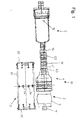
- FIG. 1 shows the sealing device 1 according to the invention, which has a storage device 2, a support sleeve 3, a bellows device 5 which can be inserted into the latter and a bellows 6 which is attached to the free end of a compressed air tube 7 (only partially shown), an injection device 10 with an injection piston 11 with injection tube 13 includes.
- the storage device 10 has a kit tube 15 which can be connected to the injection piston 11 via the injection tube 13.
- the kit tube 15 serves to receive a kit cartridge 17 according to the prior art.
- the kit used is preferably a commercially available liquid rubber.
- Attached to the kit cartridge is an impingement device, such as a pneumatic gun (not shown), which can be used, for example, to pressurize the kit cartridge 17 with a hose line (not shown) to force the kit through the tube 13 into the tube To press injection piston 11.
- the support sleeve 3 has a hollow cylindrical main body 31, at the ends of each a divided support ring 32, 33 is arranged. In the middle of its longitudinal extent, the hollow cylindrical hollow body 31 bores 34, which are arranged at regular intervals on a circumferential line in the center of the main body 31.
- the support sleeve 3 is provided for insertion into pipes to be compacted with diameters between 30 and 100 mm. Since the pipes to be sealed are usually formed of metal, in particular of aluminum, and on the other hand a certain elasticity of the support sleeve 3 is advantageous, the support sleeve 3 is preferably formed from a plastic. In particular, a material such as polytetrafluoroethylene (PTFE) is advantageous here.
- the outer side 36 of the support sleeve must be suitable for distribution and stable storage of the sealant or the sealant. For this purpose, the outer side 36 is etched to a predetermined depth with a suitable etchant and roughened thereby.
- the support sleeve 3 is preferably rotated from a solid material.
- the length of the support sleeve 3 also depends on the diameter of the tube to be sealed. The larger the diameter of the tube, the greater the length of the support sleeve 3 is provided.
- the holes 34 are provided in the support sleeve 3 to press the kit or sealant by means of the injection piston 11 from the interior of the support sleeve 3 through the holes 34 into the area between the outer side 36 of the support sleeve 3 and the inner wall of the tube to be sealed.
- the bores 34 are arranged centrally over the longitudinal extension of the support sleeve 3 in this. In this way, the sealant passes through the holes 34 at substantially the same time points to the ends or the support rings 32, 33 of the support sleeve 3.
- the holes 34 are arranged in a row, so that a uniform pressing of the sealant through the holes 34 on the Scope of the support sleeve 3 takes place.
- the number of holes 34 depends on the diameter of the tube to be sealed. With a pipe diameter of 30 mm, however, at least eight holes 34 are provided to avoid the risk of air bubbles.
- the bore diameters are in a pipe diameter of 30 mm at about 4 mm.
- the size of the bore diameter depends on the design of the injection piston 11 and in particular its injection holes 12.
- the size of the diameter of the injection bores 12 in turn depend on the diameter of the injection tube 13.
- the diameter of the injection tube 13 is in the range between 10 mm and 15 mm, with a diameter of 10 mm being used for a tube of approximately 30 mm diameter to be sealed.
- Each divided support ring 32, 33 has at the section boundaries of their subdivisions or sections 37a, 37b in the longitudinal direction 31a of the body 31 extending, elongated recesses 37c which are open at the ends of the main body 31 and in the interior of the main body 31 in each one Bore 37d merges, the diameter of which is preferably larger by about half thereof than the thickness of each recess 37c. However, the size of the diameter of the bore 37d may be provided otherwise. Seen along the circumference of the main body 31, two differently shaped sections 37a, 37b alternate.
- the design of the support rings 32, 33 with the recesses 37c and the elevations 37e have the effect of a spring action when pulling the support sleeve 3 by unevenness on the inner walls of the tube to be sealed, for example in welds or pipe joints.
- the upper limit of the number of support segments 37a results essentially from the inner diameter of the tube to be sealed.
- the longitudinal extent of the recesses 37c can be adapted to the size of the unevenness in the tube interior, in order to achieve a sufficient spring action while the outer locations of the support segments 37a on the tube interior in its flat areas.
- the bellows 6 of the bellows device 5 is designed so that the bellows 5 is fixed in a selected location within the support sleeve 3 when the bellows 6 is inflated.
- a loading device is provided. This can also be the compressed air gun 21. The compressed air is supplied to the bellows 6 through the compressed air pipe 7. Outside the tube to be sealed, the bellows 6 is brought into a selected position within the support sleeve 3 and then inflated by means of the loading device.
- the bellows 6 then serves as a stop for the injection piston 11, when the support sleeve 3 is inserted from one side into the pipe to be sealed and the injection piston is pushed from the opposite side of the pipe through this and into the support sleeve 3.
- the compressed air pipe 7 may also be designed as compressed air hose to move the support sleeve 3 by curved pipe locations.
- the bellows 6 is formed according to the prior art and comprises a body preferably of metal, in particular of aluminum, around which an inflatable rubber boot is arranged.
- the length of the compressed air pipe 7 results from the length of the pipes to be sealed. For repair of pipes within aircraft wings, a length of at least 5 m is appropriate.
- the loading device may also be provided with a pressure reducer, since the rubber sleeve of the bellows 6 is usually a pressure of 2.5 to 3 bar and is taken from conventional the supply device supplying compressed air generators compressed air at 6 to 7 bar.
- the injection piston 11 is formed cylindrically and has a first 41 and second end 42.
- the injection piston 11 of the injection device 10 is inserted into the support sleeve 3 until its first end comes to rest with the corresponding end surface of the bellows 6, which is also inserted into the injection piston 11 for positioning the injection piston 11.
- a hose connection for connection of the injection hose 13 is provided at the second end 42.
- the injection piston 11 serves as a distributor piston for distributing the sealant, ie, around the sealant from the chamber 45 through distributor bores 47 and from there through the holes 34 of the support sleeve 3 to press.
- the number of distribution holes 47 is equal to the number of holes 34 of the support sleeve 3.
- the distribution holes 47 are evenly distributed over the circumference of the injection piston 11 at intervals, which are chosen so that the distribution holes 47 in a concentric position to the bores 34 of the support sleeve 3 can be brought.
- the manifold bores 47 communicate with the chamber 45 and are located in the region of that end of the chamber 45 that is proximate to the first end 41.
- a first groove 48 extending in the circumferential direction of the injection piston 11 is provided, so that the outer, ie the supporting sleeve 3, proximal end of the distributor bores 47 is radially lower than the outside of the cylindrical base body 40.
- first sealing groove 49a Between the groove 48 and the first end 41 is a parallel to the groove 48 extending first sealing groove 49a and arranged on the opposite side of the groove 48 a likewise parallel to the groove 48 extending second sealing groove 49b.
- the first 49a and second 49b sealing groove are provided for receiving a sealing ring to prevent the leakage through the distributor bores 47 sealing compound exits uncontrollably over a predetermined area around the groove 48 around.
- the groove 48 causes the exiting through the manifold bores 47 sealant is evenly distributed over the circumference of the groove 48 while passing through the holes 34 of the support sleeve 3. This is particularly important when the distribution holes 47 are not concentric with the holes 34 of the support sleeve 3 when pressing the sealant.
- the length of the injection tube 13 depends on how far away the point of the tube to be sealed, and thus the support sleeve 3 placed in position for sealing, is removed from the corresponding open end of the tube to be sealed.
- the kit tube 15 serves to receive a kit cartridge 17, which is formed according to the prior art and contains the sealant in the filled state.
- the hose 22 is attachable, at the free end of the storage device, such as the compressed air gun 21 can be connected to generate the pressure with which the sealant from the kit cartridge 17 in the injection tube 13, the injection piston 11 and the outer region of the support sleeve 3 is pressed.
- the bellows device 5 is generally a positional device in functional terms and may also be e.g. purely mechanical, e.g. be executed by means of a stop in the support sleeve 3.
- the tube to be sealed is examined by means of a prior art endoscope and the leak site identified.
- the sealed pipe is to be opened in two places, for example, by removing appropriate fittings to get from two sides to the leakage point.
- the compressed air pipe 7 is inserted without the bellows device 5 and passed through the entire exposed pipe section until the free end of the compressed air pipe 7 emerges at the other end of the pipe section. Subsequently, the bellows device 5 is attached to the free end of the compressed air pipe 7.
- the injection piston 11 is inserted into the support sleeve 3 to a position in which the distribution holes 47 are located in the same longitudinal position in the support sleeve 3, in which the holes 34 are located , Preferably, the injection piston 11 is rotated in the support sleeve 3 so far that the distribution holes 47 are concentric with corresponding holes 34. From the corresponding side of the bellows 6 and the bellows device 5 is then inserted into the support sleeve 3 until its corresponding end comes to rest with the first end 41 of the injection piston 11.
- the bellows 6 is pressurized by means of the pressurizing device via the compressed air pipe 6 with compressed air to fix the bellows 5 in the support sleeve 3.
- the injection piston 11 can now be removed from the support sleeve 3 again.
- the support sleeve 3 is drawn by means of the compressed air tube 7 and pressed against the inner wall of the support sleeve 3 bellows 6 in the opposite opening of the pipe section and moved to the leak point.
- the support sleeve 3 is brought into a position in which the bores 34 of the support sleeve 3 in the region of the leakage point due to the done by means of the endoscope measurement of the pipe section in the leakage point in the pipe section.
- the leakage point is then preferably in the clear center between the divided support rings 32, 33rd
- the kit tube 15, the kit cartridge 17 is placed on the injection piston 11 and the hose 22 is connected to the kit cartridge 17.
- the pressurizing device or the compressed air gun is connected. If the injection piston 11 is not yet in the described position in the support sleeve 3, the injection piston 11 is guided by means of the injection tube 13 from the corresponding end of the pipe section forth in the pipe section and in the support sleeve 3 to the stop.
- the injection piston 11 is filled with the kit or the sealant. This means that only such an amount is pressed out of the kit cartridge 17 into the injection piston 11 until the sealing compound 3 begins to emerge at the bores 34 of the support sleeve 3.
- This approach ensures that enough kit mass or caulk is available for caulking.
- the process of pre-filling can be omitted.
- the kit cartridge 17 must be replaced before the actual filling or sealing process.
- the sealant or kit mass is pressed by actuation of the compressed air gun 21 of the kit cartridge 17 through the injection piston 11 and through the holes 34 of the support sleeve 3. Due to the presence of the groove 48 on the injection piston 11 and by the circumferentially of the injection piston 11 evenly distributed distribution holes 47 as well as the evenly distributed over the circumference of the support sleeve 3 holes 34, the sealant initially collects uniformly over the circumference of the support sleeve 3 in the region of the holes 34. With continued exercise of the pressure on the kit cartridge 17, the sealant moves out of the holes 34 in both opposite longitudinal directions to the support rings 32, 33. In this way it is avoided that air pockets can form.
- the duration of the pressing process depends on the temperature, the properties of the sealant. During the pressing process, this is checked by means of a camera. With the endoscopic camera is determined at what time the sealant is present at the ends of the support sleeve 3.
- the press-fitting operation could also be performed for a predetermined time, which has been determined by trial, without using an endoscopic camera. It should be avoided that too much kit is pressed in, which could close the tube. Too little kit would be disadvantageous because it does not ensure sufficient sealing.
- the compressed air pipe 7 is then held from the outside, the injection piston 11 with the injection hose 13 pulled out of the tube. At the compressed air pipe 7 can be drained, so that the bellows 6 coincides in itself. This is pushed out of the pipe with the compressed air pipe 7 and unscrewed from this.
- Usual sealants must cure for about 72 hours at a temperature range between 20 and 30 ° C. Dannach the tube is ready for use again.
Landscapes
- Engineering & Computer Science (AREA)
- General Engineering & Computer Science (AREA)
- Mechanical Engineering (AREA)
- Chemical & Material Sciences (AREA)
- Combustion & Propulsion (AREA)
- Sealing Devices (AREA)
- Examining Or Testing Airtightness (AREA)
- Infusion, Injection, And Reservoir Apparatuses (AREA)
- Gasket Seals (AREA)
Claims (7)
- Dispositif pour étanchéifier une zone de fuite du côté intérieur de tubes comprenant un dispositif de positionnement (5), un dispositif de stockage (2) et un dispositif d'injection (10) pour appliquer une masse d'étanchéité sur la zone de fuite,
caractérisé en ce que
le dispositif comprend une douille de support cylindrique (3) comprenant au moins deux alésages (34) répartis sur la périphérie et deux bagues de support (32, 33) à ses extrémités axiales,
le dispositif d'injection (10) comprend un piston d'injection (11) pouvant être inséré dans la douille de support (3), lequel piston présente des alésages (47) répartis sur la périphérie, qui sont étanchéifiés des deux côtés au moyen de joints d'étanchéité (49a, 49b) par rapport à la paroi intérieure de la douille de support (3), et peut être positionné dans la douille de support (3) au moyen d'un dispositif de positionnement (5), afin de presser la masse d'étanchéité hors du dispositif de stockage (2) par le biais du piston d'injection (11) et des alésages (34) dans la zone entre la douille de support (3) et le tube à étanchéifier. - Dispositif d'étanchéité (1) selon la revendication 1, caractérisé en ce que les alésages (34) de la douille de support (3) sont répartis axialement au centre et uniformément sur la périphérie.
- Dispositif d'étanchéité (1) selon l'une quelconque des revendications précédentes, caractérisé en ce que la douille de support (3) présente au moins huit alésages (34).
- Dispositif d'étanchéité (1) selon l'une quelconque des revendications précédentes, caractérisé en ce que les bagues de support (32, 33) de la douille de support (3) présentent des segments de support (37a) afin de prévoir un effet de ressort de la douille de support (3) contre la paroi intérieure du tube à étanchéifier.
- Dispositif d'étanchéité (1) selon l'une quelconque des revendications précédentes, caractérisé en ce que le dispositif de positionnement (5) est un dispositif à soufflet gonflable (5) avec un soufflet gonflable (6) qui peut être gonflé au moyen d'un dispositif de sollicitation en pression afin de positionner celui-ci dans la douille de support (3) en une position prédéterminée et de servir de butée pour le dispositif d'injection.
- Dispositif d'étanchéité (1) selon l'une quelconque des revendications précédentes, caractérisé en ce que le piston d'injection (11) présente en son intérieur une chambre (45) qui est en liaison d'une part avec un tuyau d'injection (13) raccordé au dispositif de stockage (2) et d'autre part avec les alésages de distribution (47).
- Procédé pour étanchéifier un tube depuis son côté intérieur, comprenant les étapes suivantes :- ouverture du tube en deux endroits de manière à ce que la zone de fuite soit accessible depuis deux côtés et enfoncement d'un dispositif de soufflet gonflable (5) depuis un premier côté du tube jusque devant la zone de fuite,- positionnement du dispositif de soufflet gonflable (5) dans une douille de support (3) avec des alésages (34), de sorte qu'un dispositif d'injection (10) introduit à l'intérieur avec des alésages de distribution (47) disposés sur la périphérie soit placé dans la douille de support (3) lors de l'application contre le dispositif de soufflet gonflable (5) de telle sorte que la position axiale des alésages (34) et des alésages de distribution (47) coïncide,- introduction de la douille de support (3) sans le dispositif d'injection (10) au moyen du dispositif de soufflet gonflable (5) dans le tube depuis son deuxième côté jusqu'à la zone de fuite, de sorte que la zone de fuite soit placée entre deux bagues de support (32, 33) prévues aux extrémités axiales de la douille de support (3),- introduction du piston d'injection (11) dans la douille de support (3) jusqu'à ce qu'elle parvienne en appui avec le dispositif de soufflet gonflable (5), de sorte que les alésages de distribution (47) soient en liaison avec les alésages (34), et raccordement d'un tube kit (15) par le biais d'un tuyau d'injection (13) au piston d'injection (11),- enfoncement de la cartouche du kit (17) et pressage de la masse d'étanchéité à travers le piston d'injection (11), les alésages de distribution (47) et les alésages (34) dans la région entre la douille de support (3) et le tube jusqu'à ce que la masse d'étanchéité parvienne aux extrémités axiales de la douille de support (3),- enlèvement du piston d'injection (11) hors de la douille de support (3) afin de laisser durcir la masse d'étanchéité entre la douille de support (3) et les parois intérieures du tube à étanchéifier.
Applications Claiming Priority (2)
| Application Number | Priority Date | Filing Date | Title |
|---|---|---|---|
| DE19933315 | 1999-07-16 | ||
| DE19933315A DE19933315C2 (de) | 1999-07-16 | 1999-07-16 | Abdichtungs-Vorrichtung und Verfahren zur Abdichtung von Rohren |
Publications (2)
| Publication Number | Publication Date |
|---|---|
| EP1069368A1 EP1069368A1 (fr) | 2001-01-17 |
| EP1069368B1 true EP1069368B1 (fr) | 2007-10-03 |
Family
ID=7914967
Family Applications (1)
| Application Number | Title | Priority Date | Filing Date |
|---|---|---|---|
| EP00114604A Expired - Lifetime EP1069368B1 (fr) | 1999-07-16 | 2000-07-07 | Dispositif d'étanchéité et procédé pour l'étanchéité de tuyaux |
Country Status (3)
| Country | Link |
|---|---|
| EP (1) | EP1069368B1 (fr) |
| AT (1) | ATE374900T1 (fr) |
| DE (2) | DE19933315C2 (fr) |
Families Citing this family (1)
| Publication number | Priority date | Publication date | Assignee | Title |
|---|---|---|---|---|
| CN107906299B (zh) * | 2017-11-15 | 2019-06-25 | 西华大学 | 一种管道内部封堵工具 |
Family Cites Families (4)
| Publication number | Priority date | Publication date | Assignee | Title |
|---|---|---|---|---|
| US3834421A (en) * | 1972-10-25 | 1974-09-10 | Penetryn Prod Inc | Packer for sealing pipe leaks |
| DE9202199U1 (de) * | 1992-02-20 | 1993-03-25 | JT Elektronik GmbH, 8990 Lindau | Packer mit aufblasbaren Dichtelementen zur Abstützung an einer Rohrwandung |
| EP0635112A4 (fr) * | 1992-03-20 | 1995-04-12 | Barry Bros Spec Services | Appareil permettant la reparation d'oleoducs et procede de reparation y afferent. |
| DE4215537A1 (de) * | 1992-05-12 | 1993-11-18 | Contraves Gmbh | Einrichtung zur Prüfung und Instandsetzung von Kanalisations- und vergleichbaren Rohrleitungen |
-
1999
- 1999-07-16 DE DE19933315A patent/DE19933315C2/de not_active Expired - Fee Related
-
2000
- 2000-07-07 AT AT00114604T patent/ATE374900T1/de not_active IP Right Cessation
- 2000-07-07 EP EP00114604A patent/EP1069368B1/fr not_active Expired - Lifetime
- 2000-07-07 DE DE50014684T patent/DE50014684D1/de not_active Expired - Fee Related
Also Published As
| Publication number | Publication date |
|---|---|
| DE19933315C2 (de) | 2001-09-06 |
| DE50014684D1 (de) | 2007-11-15 |
| EP1069368A1 (fr) | 2001-01-17 |
| ATE374900T1 (de) | 2007-10-15 |
| DE19933315A1 (de) | 2001-01-25 |
Similar Documents
| Publication | Publication Date | Title |
|---|---|---|
| DE69404757T2 (de) | Mehrstufige hydroplastische Verformung doppelwandiger Rohre | |
| DE2752072C2 (de) | Verfahren und Vorrichtung zum Abdichten von undichten Muffenverbindungen an Rohrleitungen, insbesondere an unterirdisch verlegten | |
| DE1575639B2 (de) | Walze und Verfahren zum Herstellen derselben | |
| DE2053725A1 (de) | Verfahren und Vorrichtung zum Abdich ten einer Leckstelle in Leitungen | |
| DE4232059C2 (de) | Verfahren und Vorrichtung zum Sanieren des Muffenbereichs von vorzugsweise nicht begehbaren Rohrleitungen, insbesondere Abwasserleitungen | |
| DE2313459A1 (de) | Verfahren und vorrichtung zum ausbilden einer umhuellung fuer die verbindungsstelle von unter fluidem druck stehenden roehren | |
| DE60310940T2 (de) | Verfahren zum abdichten und/oder wiederinstandsetzen von rohren | |
| DE19526992A1 (de) | Prüfverschluß für Rohre, insbesondere für Kunststoffrohre | |
| EP1069368B1 (fr) | Dispositif d'étanchéité et procédé pour l'étanchéité de tuyaux | |
| EP2282095A2 (fr) | Dispositif et procédé de fabrication d'un raccord entre deux éléments tubulaires | |
| DE4224419C2 (de) | Vorrichtung zur Abdichtung von Rohren | |
| DE2550742A1 (de) | Verfahren zur dichtigkeitspruefung der zusammenfuegungsstellen von rohren | |
| DE202011101425U1 (de) | Vorrichtung zum Verschweißen mindestens zweier Rohre | |
| DE102011103855A1 (de) | Verfahren und Vorrichtung zum Verschweißen mindestens zweier Rohre | |
| DE19804619C1 (de) | Vorrichtung und Verfahren zur Rückverformung von Rohren | |
| DE19717209A1 (de) | Rohrschelle | |
| DE1109466B (de) | Zentriereinrichtung zum Ausrichten der Innenflaechen von miteinander zu verbindendenRohren, insbesondere von Hohlleitern | |
| DE19824773C2 (de) | Vorrichtung und Verfahren zur Reparatur von Rohren | |
| EP0300169A1 (fr) | Coussin de joint pour tuyaux avec passage | |
| DE3817707A1 (de) | Verfahren und vorrichtung zum verformen von material wie hohlprofilen, rohren usw. | |
| DE2053152C (de) | Verfahren und Vorrichtung zum Aufziehen elastischer Überzüge auf Innenteile | |
| DE2530364A1 (de) | Verfahren zum pruefen der verbindungen einer rohrleitung auf dichtheit und hierfuer geeignete vorrichtung | |
| DE8701191U1 (de) | Vorrichtung zum Auffinden und zur Reparatur von Lecks in Rohrleitungen | |
| DE4426150A1 (de) | Verfahren und Vorrichtung zum Sanieren eines in einem Hauptkanal einmündenden Seitenkanals | |
| DE7931114U1 (fr) |
Legal Events
| Date | Code | Title | Description |
|---|---|---|---|
| PUAI | Public reference made under article 153(3) epc to a published international application that has entered the european phase |
Free format text: ORIGINAL CODE: 0009012 |
|
| AK | Designated contracting states |
Kind code of ref document: A1 Designated state(s): AT BE CH CY DE DK ES FI FR GB GR IE IT LI LU MC NL PT SE |
|
| AX | Request for extension of the european patent |
Free format text: AL;LT;LV;MK;RO;SI |
|
| RAP1 | Party data changed (applicant data changed or rights of an application transferred) |
Owner name: EADS DEUTSCHLAND GMBH |
|
| 17P | Request for examination filed |
Effective date: 20010113 |
|
| AKX | Designation fees paid |
Free format text: AT BE CH CY DE DK ES FI FR GB GR IE IT LI LU MC NL PT SE |
|
| GRAP | Despatch of communication of intention to grant a patent |
Free format text: ORIGINAL CODE: EPIDOSNIGR1 |
|
| GRAS | Grant fee paid |
Free format text: ORIGINAL CODE: EPIDOSNIGR3 |
|
| GRAA | (expected) grant |
Free format text: ORIGINAL CODE: 0009210 |
|
| AK | Designated contracting states |
Kind code of ref document: B1 Designated state(s): AT BE CH CY DE DK ES FI FR GB GR IE IT LI LU MC NL PT SE |
|
| REG | Reference to a national code |
Ref country code: GB Ref legal event code: FG4D Free format text: NOT ENGLISH |
|
| REG | Reference to a national code |
Ref country code: CH Ref legal event code: EP |
|
| REG | Reference to a national code |
Ref country code: IE Ref legal event code: FG4D Free format text: LANGUAGE OF EP DOCUMENT: GERMAN |
|
| REF | Corresponds to: |
Ref document number: 50014684 Country of ref document: DE Date of ref document: 20071115 Kind code of ref document: P |
|
| NLV1 | Nl: lapsed or annulled due to failure to fulfill the requirements of art. 29p and 29m of the patents act | ||
| GBV | Gb: ep patent (uk) treated as always having been void in accordance with gb section 77(7)/1977 [no translation filed] | ||
| PG25 | Lapsed in a contracting state [announced via postgrant information from national office to epo] |
Ref country code: SE Free format text: LAPSE BECAUSE OF FAILURE TO SUBMIT A TRANSLATION OF THE DESCRIPTION OR TO PAY THE FEE WITHIN THE PRESCRIBED TIME-LIMIT Effective date: 20080103 Ref country code: ES Free format text: LAPSE BECAUSE OF FAILURE TO SUBMIT A TRANSLATION OF THE DESCRIPTION OR TO PAY THE FEE WITHIN THE PRESCRIBED TIME-LIMIT Effective date: 20080114 Ref country code: NL Free format text: LAPSE BECAUSE OF FAILURE TO SUBMIT A TRANSLATION OF THE DESCRIPTION OR TO PAY THE FEE WITHIN THE PRESCRIBED TIME-LIMIT Effective date: 20071003 |
|
| PG25 | Lapsed in a contracting state [announced via postgrant information from national office to epo] |
Ref country code: PT Free format text: LAPSE BECAUSE OF FAILURE TO SUBMIT A TRANSLATION OF THE DESCRIPTION OR TO PAY THE FEE WITHIN THE PRESCRIBED TIME-LIMIT Effective date: 20080303 |
|
| REG | Reference to a national code |
Ref country code: IE Ref legal event code: FD4D |
|
| EN | Fr: translation not filed | ||
| PG25 | Lapsed in a contracting state [announced via postgrant information from national office to epo] |
Ref country code: DK Free format text: LAPSE BECAUSE OF FAILURE TO SUBMIT A TRANSLATION OF THE DESCRIPTION OR TO PAY THE FEE WITHIN THE PRESCRIBED TIME-LIMIT Effective date: 20071003 |
|
| PLBE | No opposition filed within time limit |
Free format text: ORIGINAL CODE: 0009261 |
|
| STAA | Information on the status of an ep patent application or granted ep patent |
Free format text: STATUS: NO OPPOSITION FILED WITHIN TIME LIMIT |
|
| 26N | No opposition filed |
Effective date: 20080704 |
|
| PG25 | Lapsed in a contracting state [announced via postgrant information from national office to epo] |
Ref country code: IE Free format text: LAPSE BECAUSE OF FAILURE TO SUBMIT A TRANSLATION OF THE DESCRIPTION OR TO PAY THE FEE WITHIN THE PRESCRIBED TIME-LIMIT Effective date: 20071003 Ref country code: FR Free format text: LAPSE BECAUSE OF FAILURE TO SUBMIT A TRANSLATION OF THE DESCRIPTION OR TO PAY THE FEE WITHIN THE PRESCRIBED TIME-LIMIT Effective date: 20080704 |
|
| PG25 | Lapsed in a contracting state [announced via postgrant information from national office to epo] |
Ref country code: GB Free format text: LAPSE BECAUSE OF FAILURE TO SUBMIT A TRANSLATION OF THE DESCRIPTION OR TO PAY THE FEE WITHIN THE PRESCRIBED TIME-LIMIT Effective date: 20071003 |
|
| PG25 | Lapsed in a contracting state [announced via postgrant information from national office to epo] |
Ref country code: GR Free format text: LAPSE BECAUSE OF FAILURE TO SUBMIT A TRANSLATION OF THE DESCRIPTION OR TO PAY THE FEE WITHIN THE PRESCRIBED TIME-LIMIT Effective date: 20080104 |
|
| REG | Reference to a national code |
Ref country code: CH Ref legal event code: PL |
|
| PG25 | Lapsed in a contracting state [announced via postgrant information from national office to epo] |
Ref country code: MC Free format text: LAPSE BECAUSE OF NON-PAYMENT OF DUE FEES Effective date: 20080731 |
|
| PG25 | Lapsed in a contracting state [announced via postgrant information from national office to epo] |
Ref country code: DE Free format text: LAPSE BECAUSE OF NON-PAYMENT OF DUE FEES Effective date: 20090203 |
|
| PG25 | Lapsed in a contracting state [announced via postgrant information from national office to epo] |
Ref country code: CH Free format text: LAPSE BECAUSE OF NON-PAYMENT OF DUE FEES Effective date: 20080731 Ref country code: LI Free format text: LAPSE BECAUSE OF NON-PAYMENT OF DUE FEES Effective date: 20080731 |
|
| PG25 | Lapsed in a contracting state [announced via postgrant information from national office to epo] |
Ref country code: CY Free format text: LAPSE BECAUSE OF FAILURE TO SUBMIT A TRANSLATION OF THE DESCRIPTION OR TO PAY THE FEE WITHIN THE PRESCRIBED TIME-LIMIT Effective date: 20071003 |
|
| PG25 | Lapsed in a contracting state [announced via postgrant information from national office to epo] |
Ref country code: AT Free format text: LAPSE BECAUSE OF NON-PAYMENT OF DUE FEES Effective date: 20080707 |
|
| PG25 | Lapsed in a contracting state [announced via postgrant information from national office to epo] |
Ref country code: FI Free format text: LAPSE BECAUSE OF FAILURE TO SUBMIT A TRANSLATION OF THE DESCRIPTION OR TO PAY THE FEE WITHIN THE PRESCRIBED TIME-LIMIT Effective date: 20071003 |
|
| PG25 | Lapsed in a contracting state [announced via postgrant information from national office to epo] |
Ref country code: LU Free format text: LAPSE BECAUSE OF NON-PAYMENT OF DUE FEES Effective date: 20080707 |
|
| PG25 | Lapsed in a contracting state [announced via postgrant information from national office to epo] |
Ref country code: BE Free format text: LAPSE BECAUSE OF NON-PAYMENT OF DUE FEES Effective date: 20080731 |
|
| PG25 | Lapsed in a contracting state [announced via postgrant information from national office to epo] |
Ref country code: IT Free format text: LAPSE BECAUSE OF NON-PAYMENT OF DUE FEES Effective date: 20080731 |