EP1069326B1 - Halteelement zur lösbaren Befestigung auf einem längsgerippten Kunststoffbolzen - Google Patents
Halteelement zur lösbaren Befestigung auf einem längsgerippten Kunststoffbolzen Download PDFInfo
- Publication number
- EP1069326B1 EP1069326B1 EP00112982A EP00112982A EP1069326B1 EP 1069326 B1 EP1069326 B1 EP 1069326B1 EP 00112982 A EP00112982 A EP 00112982A EP 00112982 A EP00112982 A EP 00112982A EP 1069326 B1 EP1069326 B1 EP 1069326B1
- Authority
- EP
- European Patent Office
- Prior art keywords
- cage
- bolt
- support
- accommodating
- hole
- Prior art date
- Legal status (The legal status is an assumption and is not a legal conclusion. Google has not performed a legal analysis and makes no representation as to the accuracy of the status listed.)
- Expired - Lifetime
Links
- 229920003023 plastic Polymers 0.000 title claims abstract description 8
- 239000004033 plastic Substances 0.000 title claims abstract description 8
- 230000001154 acute effect Effects 0.000 claims 1
- 230000000284 resting effect Effects 0.000 abstract 1
- 238000005452 bending Methods 0.000 description 2
- 230000037431 insertion Effects 0.000 description 2
- 238000003780 insertion Methods 0.000 description 2
- 230000001419 dependent effect Effects 0.000 description 1
Images
Classifications
-
- F—MECHANICAL ENGINEERING; LIGHTING; HEATING; WEAPONS; BLASTING
- F16—ENGINEERING ELEMENTS AND UNITS; GENERAL MEASURES FOR PRODUCING AND MAINTAINING EFFECTIVE FUNCTIONING OF MACHINES OR INSTALLATIONS; THERMAL INSULATION IN GENERAL
- F16B—DEVICES FOR FASTENING OR SECURING CONSTRUCTIONAL ELEMENTS OR MACHINE PARTS TOGETHER, e.g. NAILS, BOLTS, CIRCLIPS, CLAMPS, CLIPS OR WEDGES; JOINTS OR JOINTING
- F16B21/00—Means for preventing relative axial movement of a pin, spigot, shaft or the like and a member surrounding it; Stud-and-socket releasable fastenings
- F16B21/06—Releasable fastening devices with snap-action
- F16B21/07—Releasable fastening devices with snap-action in which the socket has a resilient part
- F16B21/073—Releasable fastening devices with snap-action in which the socket has a resilient part the socket having a resilient part on its inside
-
- Y—GENERAL TAGGING OF NEW TECHNOLOGICAL DEVELOPMENTS; GENERAL TAGGING OF CROSS-SECTIONAL TECHNOLOGIES SPANNING OVER SEVERAL SECTIONS OF THE IPC; TECHNICAL SUBJECTS COVERED BY FORMER USPC CROSS-REFERENCE ART COLLECTIONS [XRACs] AND DIGESTS
- Y10—TECHNICAL SUBJECTS COVERED BY FORMER USPC
- Y10S—TECHNICAL SUBJECTS COVERED BY FORMER USPC CROSS-REFERENCE ART COLLECTIONS [XRACs] AND DIGESTS
- Y10S411/00—Expanded, threaded, driven, headed, tool-deformed, or locked-threaded fastener
- Y10S411/904—Fastener or fastener element composed of nonmetallic material
- Y10S411/908—Resinous material
Definitions
- the invention relates to a holding element according to the preamble of claim 1.
- Such a holding element is known from GB 2 129 863 A. at the previously known retaining element settles into a cage space of a Receiving cage of the holding element protruding and with a Support edge trained support arm on a introduced into the cage space Bolt, passing through the biased by the support arm applied force the support edge engages the bolt. In order to a good attachment of the retaining element is achieved on the bolt, which, however, can not be solved without further ado.
- the invention is based on the object, a holding element of the above specify the type mentioned, by a proportionate easy solubility of a bolt distinguishes.
- the retaining element shown in the figures consists of a receiving cage 1 made of hard elastic plastic with an insertable on the bolt 5 inner wall 2 and a support arm 3 which is formed on the inner wall 2 opposite side of the receiving cage 1 elastically auffederbar.
- This support arm 3 is directed against the pressing direction A at an angle ⁇ on the opposite inner wall 2 , wherein the distance of the support edge 13 to the inner wall 2 is smaller than the outer diameter of the bolt fifth
- a through hole 8 and 9 for insertion and passage of the bolt 5 is provided in each case.
- At the lower transverse wall 6 are also formed on three sides obliquely downwardly projecting support wings 10 auffederbar.
- the provided for pressing the retaining element bolt 5 is also made of plastic and is evenly distributed over its circumference, provided with axially parallel longitudinal ribs 11 .
- the bolt 5 itself is held by a support plate 12 on which the receiving cage 1 is supported with the support wings 10 after pressing.
- the support arm 3 is provided at its free end with an acute-angled support edge 13 and also has a support nose 14 above it. Further, located on the top of the support arm 3, a Entriegelungssteg 15 which, opposite to the pressing A , on the support arm 3 is formed. In order to be able to actuate the unlocking web 15 more easily with a tool, such as a flat-nose pliers, a recess 16 sufficiently large for insertion of the pliers is recessed in the upper transverse wall 7 .
- the receiving cage 1 lifts slightly under the spring force of the support wings 10 in the direction of arrow Z , wherein the support edge 13 digs into the longitudinal ribs 11 , and indeed so far until the support lug 14 rests against the ribs 11 .
- the support arm 3 is now firmly anchored on the bolt 5 and can only be solved by bending back the Entriegelungssteges 15 again from the pin 5 .
Landscapes
- Engineering & Computer Science (AREA)
- General Engineering & Computer Science (AREA)
- Mechanical Engineering (AREA)
- Insertion Pins And Rivets (AREA)
- Snaps, Bayonet Connections, Set Pins, And Snap Rings (AREA)
- Joining Of Building Structures In Genera (AREA)
- Connection Of Plates (AREA)
- Fittings On The Vehicle Exterior For Carrying Loads, And Devices For Holding Or Mounting Articles (AREA)
- Supports Or Holders For Household Use (AREA)
- Prostheses (AREA)
- Orthopedics, Nursing, And Contraception (AREA)
Description
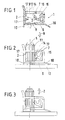
- Fig.1
- einen Schnitt durch ein Ausführungsbeispiel eines erfindungsgemäßen Halteelementes,
- Fig. 2
- das Halteelement gemäß Fig. 1 in einer Seitenansicht beim Aufdrücken auf einen gerippten Kunststoffbolzen und
- Fig. 3
- die gleiche Befestigungssituation unter Einwirkung einer Zugkraft.
Claims (4)
- Halteelement aus hartelastischem Kunststoff zur lösbaren Befestigung auf einem mit achsparallelen Längsrippen versehenen Bolzen (5) aus Kunststoff mit einem Aufnahmekäfig (1), der eine Innenwand (2) sowie einen Stützarm (3) aufweist, welcher auf der gegenüberliegenden Seite der Innenwand (2) am Aufnahmekäfig (1) auffederbar angeformt und von einem Durchgangsloch (8) zum Einführen des Bolzens (5) in einen Käfigraum (4) des Aufnahmekäfigs (1) wegweisend unter einem dem Durchgangsloch zugewandten Winkel (α) kleiner 90° auf die Innenwand (2) gerichtet ist, wobei der Stützarm (3) an seinem freien Ende mit einer spitzwinklig ausgebildeten, zum Eingriff mit dem Bolzen (5) eingerichteten Stützkante (13) versehen ist, die sich im montierten Zustand in die Längsrippen eingräbt dadurch gekennzeichnet, daß auf der von dem Durchgangsloch (8) wegweisenden Seite des Stützarms (3) ein Entriegelungssteg (15) angeformt ist
- Halteelement nach Anspruch 1, dadurch gekennzeichnet, daß auf der von dem Durchgangsloch (8) abgewandten Seite der Stützkante (13) eine sich bei einem eingeführten Bolzen (5) an die Längsrippen ( 11 ) anlegende Stütznase (14) vorgesehen ist.
- Halteelement nach Anspruch 1 oder 2, dadurch gekennzeichnet, daß an der Innenwand (2) mindestens eine in den Käfigraum (4) gerichtete und quer zu der Längsrichtung des Aufnahmekäfigs (1), d.h. quer zur Einführrichtung des Bolzens in den Aufnahmekäfig, ausgerichtete spitzwinklige Rippe (17) angeformt ist.
- Halteelement nach einem der Ansprüche 1 bis 3, dadurch gekennzeichnet, daß an einer das Durchgangsloch (8) aufnehmenden Querwand (6) des Aufnahmekäfigs (1) nach mindestens drei Seiten des Aufnahmekäfigs schräg von dem Käfigraum (4) wegweisend abstehende Auflageflügel (10) auffederbar angeformt sind.
Applications Claiming Priority (2)
| Application Number | Priority Date | Filing Date | Title |
|---|---|---|---|
| DE19932862 | 1999-07-14 | ||
| DE19932862A DE19932862A1 (de) | 1999-07-14 | 1999-07-14 | Halteelement zur lösbaren Befestigung auf einem längsgerippten Kunststoffbolzen |
Publications (3)
| Publication Number | Publication Date |
|---|---|
| EP1069326A2 EP1069326A2 (de) | 2001-01-17 |
| EP1069326A3 EP1069326A3 (de) | 2002-01-30 |
| EP1069326B1 true EP1069326B1 (de) | 2005-04-20 |
Family
ID=7914721
Family Applications (1)
| Application Number | Title | Priority Date | Filing Date |
|---|---|---|---|
| EP00112982A Expired - Lifetime EP1069326B1 (de) | 1999-07-14 | 2000-06-21 | Halteelement zur lösbaren Befestigung auf einem längsgerippten Kunststoffbolzen |
Country Status (6)
| Country | Link |
|---|---|
| US (1) | US6338602B1 (de) |
| EP (1) | EP1069326B1 (de) |
| JP (1) | JP2001050227A (de) |
| AT (1) | ATE293760T1 (de) |
| DE (2) | DE19932862A1 (de) |
| ES (1) | ES2239967T3 (de) |
Cited By (1)
| Publication number | Priority date | Publication date | Assignee | Title |
|---|---|---|---|---|
| DE102008007135A1 (de) | 2008-01-31 | 2009-08-06 | Newfrey Llc, Newark | Befestigungselement |
Families Citing this family (10)
| Publication number | Priority date | Publication date | Assignee | Title |
|---|---|---|---|---|
| ATE338183T1 (de) * | 1999-02-16 | 2006-09-15 | Intier Automotive Closures Inc | Verbindungsklammer für eine türschlossvorrichtung |
| DE10040757C1 (de) | 2000-08-19 | 2001-09-27 | Raymond A & Cie | Halteclip zur Befestigung von Funktionselementen auf einem Bolzen |
| US8883064B2 (en) | 2011-06-02 | 2014-11-11 | A. Raymond & Cie | Method of making printed fastener |
| US8916085B2 (en) | 2011-06-02 | 2014-12-23 | A. Raymond Et Cie | Process of making a component with a passageway |
| CN103717378B (zh) | 2011-06-02 | 2016-04-27 | A·雷蒙德公司 | 通过三维印刷制造的紧固件 |
| KR102205052B1 (ko) * | 2012-11-15 | 2021-01-22 | 신세스 게엠바하 | 골 고정 장치를 위한 로킹 부재 |
| JP6240060B2 (ja) * | 2014-12-18 | 2017-11-29 | トヨタ自動車株式会社 | 被保持部材の仮止め具および保持具 |
| DE102019117232A1 (de) * | 2019-06-26 | 2020-12-31 | Illinois Tool Works Inc. | Bolzenaufnahme |
| JP7354990B2 (ja) * | 2020-11-05 | 2023-10-03 | トヨタ自動車株式会社 | 車両の製造方法 |
| CN116067556B (zh) * | 2021-11-04 | 2024-11-26 | 精量电子(深圳)有限公司 | 密封销、压力检测模块和压力传感器 |
Family Cites Families (10)
| Publication number | Priority date | Publication date | Assignee | Title |
|---|---|---|---|---|
| US3385154A (en) * | 1966-12-12 | 1968-05-28 | Louis F. Miklos | Sheet metal fastener |
| US3374859A (en) * | 1967-07-24 | 1968-03-26 | Creative Associates Of Albany | Anchor device with releasable latch means |
| SE455435B (sv) * | 1982-10-15 | 1988-07-11 | Usm Corp | Plastklemma for infestning av ett ror vid en fran en yta utskjutande tapp |
| US4547108A (en) * | 1983-11-25 | 1985-10-15 | Nifco Inc. | Trim cover clip |
| JP2524861Y2 (ja) * | 1991-12-09 | 1997-02-05 | 矢崎総業株式会社 | ボルト係止用の係止部構造 |
| JP2577276Y2 (ja) * | 1992-06-10 | 1998-07-23 | 株式会社ニフコ | マット状物の止め具 |
| DE4427723C2 (de) | 1994-08-05 | 2002-06-06 | Raymond A & Cie | Zweiteiliges Befestigungssystem |
| US5816762A (en) * | 1996-07-09 | 1998-10-06 | Illinois Tool Works Inc. | Stud clip having different insertion/withdrawal forces |
| JP2000018223A (ja) * | 1998-07-06 | 2000-01-18 | Pop Rivet Fastener Kk | 溶着スタッド |
| FR2782133B1 (fr) * | 1998-08-07 | 2000-11-03 | Itw De France | Article encliquetable sur une tige filetee et son utilisation |
-
1999
- 1999-07-14 DE DE19932862A patent/DE19932862A1/de not_active Withdrawn
-
2000
- 2000-06-21 AT AT00112982T patent/ATE293760T1/de not_active IP Right Cessation
- 2000-06-21 EP EP00112982A patent/EP1069326B1/de not_active Expired - Lifetime
- 2000-06-21 ES ES00112982T patent/ES2239967T3/es not_active Expired - Lifetime
- 2000-06-21 DE DE50010082T patent/DE50010082D1/de not_active Expired - Lifetime
- 2000-07-11 JP JP2000210173A patent/JP2001050227A/ja active Pending
- 2000-07-12 US US09/614,985 patent/US6338602B1/en not_active Expired - Fee Related
Cited By (1)
| Publication number | Priority date | Publication date | Assignee | Title |
|---|---|---|---|---|
| DE102008007135A1 (de) | 2008-01-31 | 2009-08-06 | Newfrey Llc, Newark | Befestigungselement |
Also Published As
| Publication number | Publication date |
|---|---|
| EP1069326A3 (de) | 2002-01-30 |
| EP1069326A2 (de) | 2001-01-17 |
| ES2239967T3 (es) | 2005-10-16 |
| ATE293760T1 (de) | 2005-05-15 |
| US6338602B1 (en) | 2002-01-15 |
| DE50010082D1 (de) | 2005-05-25 |
| JP2001050227A (ja) | 2001-02-23 |
| DE19932862A1 (de) | 2001-01-18 |
Similar Documents
| Publication | Publication Date | Title |
|---|---|---|
| DE8520800U1 (de) | Plattenhalter | |
| DE69922105T2 (de) | Rasthaken | |
| EP1729388A2 (de) | Befestigungsvorrichtung für mehrere Leitungen | |
| EP1069326B1 (de) | Halteelement zur lösbaren Befestigung auf einem längsgerippten Kunststoffbolzen | |
| DE102005020011A1 (de) | Clip und Befestigungssystem mit einem Clip | |
| DE1909970A1 (de) | Aus einem Stueck bestehendes Befestigungselement | |
| EP2198170B1 (de) | Vorrichtung zum befestigen eines anbauteiles an einem trägerteil | |
| DE102020120766A1 (de) | Befestigungseinrichtung, Verfahren, Anordnung und Schaltschrank | |
| EP2183736B1 (de) | Kennzeichnungsvorrichtung für elektrische leitungen | |
| DE102016204483B4 (de) | Befestigungselement mit mindestens einem Clip zur Herstellung einer Verbindung mit einem korrespondierenden Ansteckelement und Anordnung eines Befestigungselements an einem Ansteckelement | |
| DE102016103169B4 (de) | Adapter zur Fixierung eines Bodens an einer Seitenzarge, Schubkasten und Verfahren zur Montage eines Bodens an einem Adapter | |
| DE19632536C2 (de) | Vorrichtung zum Befestigen eines Einbaugerätes, insbesondere einer Steckdose | |
| DE29615341U1 (de) | Adapter für Stromschienensysteme | |
| EP0300177B1 (de) | Endstück zum Führen von Lamellen | |
| DE9016393U1 (de) | Vorrichtung zum Verbinden mehrerer Teile | |
| DE102018102411A1 (de) | Kodiertes Konstruktionsbauteil, insbesondere kodiertes Gerüstbauteil oder kodiertes Schalungsbauteil sowie Verfahren zur Montage eines Informationsträgers an einem Konstruktionsbauteil sowie Informationsträger | |
| DE1965109A1 (de) | Metall-Federklammer | |
| WO2012079857A1 (de) | Wischblattvorrichtung | |
| DE102007047416B3 (de) | Befestigungseinrichtung für eine Fahrzeugantenne | |
| DE10005759A1 (de) | Mitnehmer zur Anbindung einer Fensterscheibe an einem Fensterheber | |
| DE10328020A1 (de) | Aufhängevorrichtung zur schwingungsdämpfenden Befestigung einer Abgasanlage an einem Fahrzeugbauteil | |
| DE102008007135A1 (de) | Befestigungselement | |
| AT523631B1 (de) | Vorrichtung zur Befestigung einer Abschlussleiste | |
| EP3447205B1 (de) | Anordnung einer abdeckung an einer rinne | |
| EP0834656B1 (de) | Einrichtung zum Befestigen eines Bauteils an einer Wand, insbesondere der Wand einer Kraftfahrzeugkarosserie |
Legal Events
| Date | Code | Title | Description |
|---|---|---|---|
| PUAI | Public reference made under article 153(3) epc to a published international application that has entered the european phase |
Free format text: ORIGINAL CODE: 0009012 |
|
| AK | Designated contracting states |
Kind code of ref document: A2 Designated state(s): AT BE CH CY DE DK ES FI FR GB GR IE IT LI LU MC NL PT SE |
|
| AX | Request for extension of the european patent |
Free format text: AL;LT;LV;MK;RO;SI |
|
| PUAL | Search report despatched |
Free format text: ORIGINAL CODE: 0009013 |
|
| AK | Designated contracting states |
Kind code of ref document: A3 Designated state(s): AT BE CH CY DE DK ES FI FR GB GR IE IT LI LU MC NL PT SE |
|
| AX | Request for extension of the european patent |
Free format text: AL;LT;LV;MK;RO;SI |
|
| 17P | Request for examination filed |
Effective date: 20020730 |
|
| AKX | Designation fees paid |
Free format text: AT BE CH CY DE DK ES FI FR GB GR IE IT LI LU MC NL PT SE |
|
| 17Q | First examination report despatched |
Effective date: 20040206 |
|
| GRAP | Despatch of communication of intention to grant a patent |
Free format text: ORIGINAL CODE: EPIDOSNIGR1 |
|
| GRAS | Grant fee paid |
Free format text: ORIGINAL CODE: EPIDOSNIGR3 |
|
| GRAA | (expected) grant |
Free format text: ORIGINAL CODE: 0009210 |
|
| AK | Designated contracting states |
Kind code of ref document: B1 Designated state(s): AT BE CH CY DE DK ES FI FR GB GR IE IT LI LU MC NL PT SE |
|
| PG25 | Lapsed in a contracting state [announced via postgrant information from national office to epo] |
Ref country code: FI Free format text: LAPSE BECAUSE OF FAILURE TO SUBMIT A TRANSLATION OF THE DESCRIPTION OR TO PAY THE FEE WITHIN THE PRESCRIBED TIME-LIMIT Effective date: 20050420 Ref country code: NL Free format text: LAPSE BECAUSE OF FAILURE TO SUBMIT A TRANSLATION OF THE DESCRIPTION OR TO PAY THE FEE WITHIN THE PRESCRIBED TIME-LIMIT Effective date: 20050420 Ref country code: IE Free format text: LAPSE BECAUSE OF FAILURE TO SUBMIT A TRANSLATION OF THE DESCRIPTION OR TO PAY THE FEE WITHIN THE PRESCRIBED TIME-LIMIT Effective date: 20050420 |
|
| REG | Reference to a national code |
Ref country code: GB Ref legal event code: FG4D Free format text: NOT ENGLISH |
|
| REG | Reference to a national code |
Ref country code: CH Ref legal event code: EP |
|
| REG | Reference to a national code |
Ref country code: IE Ref legal event code: FG4D Free format text: LANGUAGE OF EP DOCUMENT: GERMAN |
|
| REF | Corresponds to: |
Ref document number: 50010082 Country of ref document: DE Date of ref document: 20050525 Kind code of ref document: P |
|
| PG25 | Lapsed in a contracting state [announced via postgrant information from national office to epo] |
Ref country code: LU Free format text: LAPSE BECAUSE OF NON-PAYMENT OF DUE FEES Effective date: 20050621 Ref country code: CY Free format text: LAPSE BECAUSE OF FAILURE TO SUBMIT A TRANSLATION OF THE DESCRIPTION OR TO PAY THE FEE WITHIN THE PRESCRIBED TIME-LIMIT Effective date: 20050621 Ref country code: AT Free format text: LAPSE BECAUSE OF NON-PAYMENT OF DUE FEES Effective date: 20050621 |
|
| GBT | Gb: translation of ep patent filed (gb section 77(6)(a)/1977) |
Effective date: 20050601 |
|
| PG25 | Lapsed in a contracting state [announced via postgrant information from national office to epo] |
Ref country code: CH Free format text: LAPSE BECAUSE OF NON-PAYMENT OF DUE FEES Effective date: 20050630 Ref country code: LI Free format text: LAPSE BECAUSE OF NON-PAYMENT OF DUE FEES Effective date: 20050630 Ref country code: MC Free format text: LAPSE BECAUSE OF NON-PAYMENT OF DUE FEES Effective date: 20050630 |
|
| PG25 | Lapsed in a contracting state [announced via postgrant information from national office to epo] |
Ref country code: GR Free format text: LAPSE BECAUSE OF FAILURE TO SUBMIT A TRANSLATION OF THE DESCRIPTION OR TO PAY THE FEE WITHIN THE PRESCRIBED TIME-LIMIT Effective date: 20050720 Ref country code: DK Free format text: LAPSE BECAUSE OF FAILURE TO SUBMIT A TRANSLATION OF THE DESCRIPTION OR TO PAY THE FEE WITHIN THE PRESCRIBED TIME-LIMIT Effective date: 20050720 Ref country code: SE Free format text: LAPSE BECAUSE OF FAILURE TO SUBMIT A TRANSLATION OF THE DESCRIPTION OR TO PAY THE FEE WITHIN THE PRESCRIBED TIME-LIMIT Effective date: 20050720 |
|
| PG25 | Lapsed in a contracting state [announced via postgrant information from national office to epo] |
Ref country code: PT Free format text: LAPSE BECAUSE OF FAILURE TO SUBMIT A TRANSLATION OF THE DESCRIPTION OR TO PAY THE FEE WITHIN THE PRESCRIBED TIME-LIMIT Effective date: 20050920 |
|
| REG | Reference to a national code |
Ref country code: ES Ref legal event code: FG2A Ref document number: 2239967 Country of ref document: ES Kind code of ref document: T3 |
|
| NLV1 | Nl: lapsed or annulled due to failure to fulfill the requirements of art. 29p and 29m of the patents act | ||
| REG | Reference to a national code |
Ref country code: IE Ref legal event code: FD4D |
|
| REG | Reference to a national code |
Ref country code: CH Ref legal event code: PL |
|
| PLBE | No opposition filed within time limit |
Free format text: ORIGINAL CODE: 0009261 |
|
| STAA | Information on the status of an ep patent application or granted ep patent |
Free format text: STATUS: NO OPPOSITION FILED WITHIN TIME LIMIT |
|
| 26N | No opposition filed |
Effective date: 20060123 |
|
| EN | Fr: translation not filed | ||
| PGFP | Annual fee paid to national office [announced via postgrant information from national office to epo] |
Ref country code: GB Payment date: 20080523 Year of fee payment: 9 |
|
| PGFP | Annual fee paid to national office [announced via postgrant information from national office to epo] |
Ref country code: FR Payment date: 20070630 Year of fee payment: 8 |
|
| GBPC | Gb: european patent ceased through non-payment of renewal fee |
Effective date: 20090621 |
|
| PG25 | Lapsed in a contracting state [announced via postgrant information from national office to epo] |
Ref country code: GB Free format text: LAPSE BECAUSE OF NON-PAYMENT OF DUE FEES Effective date: 20090621 |
|
| PGFP | Annual fee paid to national office [announced via postgrant information from national office to epo] |
Ref country code: ES Payment date: 20100510 Year of fee payment: 11 |
|
| PG25 | Lapsed in a contracting state [announced via postgrant information from national office to epo] |
Ref country code: FR Free format text: LAPSE BECAUSE OF NON-PAYMENT OF DUE FEES Effective date: 20080629 |
|
| PGFP | Annual fee paid to national office [announced via postgrant information from national office to epo] |
Ref country code: BE Payment date: 20100701 Year of fee payment: 11 |
|
| PGFP | Annual fee paid to national office [announced via postgrant information from national office to epo] |
Ref country code: IT Payment date: 20110615 Year of fee payment: 12 Ref country code: DE Payment date: 20110503 Year of fee payment: 12 |
|
| BERE | Be: lapsed |
Owner name: A. *RAYMOND & CIE Effective date: 20110630 |
|
| PG25 | Lapsed in a contracting state [announced via postgrant information from national office to epo] |
Ref country code: BE Free format text: LAPSE BECAUSE OF NON-PAYMENT OF DUE FEES Effective date: 20110630 |
|
| PG25 | Lapsed in a contracting state [announced via postgrant information from national office to epo] |
Ref country code: IT Free format text: LAPSE BECAUSE OF NON-PAYMENT OF DUE FEES Effective date: 20120621 |
|
| REG | Reference to a national code |
Ref country code: DE Ref legal event code: R119 Ref document number: 50010082 Country of ref document: DE Effective date: 20130101 |
|
| PG25 | Lapsed in a contracting state [announced via postgrant information from national office to epo] |
Ref country code: DE Free format text: LAPSE BECAUSE OF NON-PAYMENT OF DUE FEES Effective date: 20130101 |
|
| REG | Reference to a national code |
Ref country code: ES Ref legal event code: FD2A Effective date: 20130823 |
|
| PG25 | Lapsed in a contracting state [announced via postgrant information from national office to epo] |
Ref country code: ES Free format text: LAPSE BECAUSE OF NON-PAYMENT OF DUE FEES Effective date: 20110622 |