EP1069303A2 - Brennkraftmaschine mit Abgasrückführung und Verfahren zur Abgasrückführung - Google Patents
Brennkraftmaschine mit Abgasrückführung und Verfahren zur Abgasrückführung Download PDFInfo
- Publication number
- EP1069303A2 EP1069303A2 EP00113182A EP00113182A EP1069303A2 EP 1069303 A2 EP1069303 A2 EP 1069303A2 EP 00113182 A EP00113182 A EP 00113182A EP 00113182 A EP00113182 A EP 00113182A EP 1069303 A2 EP1069303 A2 EP 1069303A2
- Authority
- EP
- European Patent Office
- Prior art keywords
- exhaust gas
- gas recirculation
- intake
- intake manifold
- combustion engine
- Prior art date
- Legal status (The legal status is an assumption and is not a legal conclusion. Google has not performed a legal analysis and makes no representation as to the accuracy of the status listed.)
- Withdrawn
Links
- 238000002485 combustion reaction Methods 0.000 title claims abstract description 20
- 238000000034 method Methods 0.000 title claims description 7
- 230000003134 recirculating effect Effects 0.000 title claims description 3
- 239000002826 coolant Substances 0.000 claims 1
- 238000001816 cooling Methods 0.000 description 7
- 238000009434 installation Methods 0.000 description 4
- 230000001419 dependent effect Effects 0.000 description 2
- 239000000203 mixture Substances 0.000 description 2
- 229910001220 stainless steel Inorganic materials 0.000 description 2
- 239000010935 stainless steel Substances 0.000 description 2
- 230000008646 thermal stress Effects 0.000 description 2
- 230000000694 effects Effects 0.000 description 1
- 238000010438 heat treatment Methods 0.000 description 1
- 230000005855 radiation Effects 0.000 description 1
- 238000007789 sealing Methods 0.000 description 1
- 239000013585 weight reducing agent Substances 0.000 description 1
Images

Classifications
-
- F—MECHANICAL ENGINEERING; LIGHTING; HEATING; WEAPONS; BLASTING
- F02—COMBUSTION ENGINES; HOT-GAS OR COMBUSTION-PRODUCT ENGINE PLANTS
- F02M—SUPPLYING COMBUSTION ENGINES IN GENERAL WITH COMBUSTIBLE MIXTURES OR CONSTITUENTS THEREOF
- F02M35/00—Combustion-air cleaners, air intakes, intake silencers, or induction systems specially adapted for, or arranged on, internal-combustion engines
- F02M35/10—Air intakes; Induction systems
- F02M35/10209—Fluid connections to the air intake system; their arrangement of pipes, valves or the like
- F02M35/10222—Exhaust gas recirculation [EGR]; Positive crankcase ventilation [PCV]; Additional air admission, lubricant or fuel vapour admission
-
- F—MECHANICAL ENGINEERING; LIGHTING; HEATING; WEAPONS; BLASTING
- F02—COMBUSTION ENGINES; HOT-GAS OR COMBUSTION-PRODUCT ENGINE PLANTS
- F02M—SUPPLYING COMBUSTION ENGINES IN GENERAL WITH COMBUSTIBLE MIXTURES OR CONSTITUENTS THEREOF
- F02M26/00—Engine-pertinent apparatus for adding exhaust gases to combustion-air, main fuel or fuel-air mixture, e.g. by exhaust gas recirculation [EGR] systems
- F02M26/13—Arrangement or layout of EGR passages, e.g. in relation to specific engine parts or for incorporation of accessories
- F02M26/17—Arrangement or layout of EGR passages, e.g. in relation to specific engine parts or for incorporation of accessories in relation to the intake system
-
- F—MECHANICAL ENGINEERING; LIGHTING; HEATING; WEAPONS; BLASTING
- F02—COMBUSTION ENGINES; HOT-GAS OR COMBUSTION-PRODUCT ENGINE PLANTS
- F02M—SUPPLYING COMBUSTION ENGINES IN GENERAL WITH COMBUSTIBLE MIXTURES OR CONSTITUENTS THEREOF
- F02M26/00—Engine-pertinent apparatus for adding exhaust gases to combustion-air, main fuel or fuel-air mixture, e.g. by exhaust gas recirculation [EGR] systems
- F02M26/13—Arrangement or layout of EGR passages, e.g. in relation to specific engine parts or for incorporation of accessories
- F02M26/22—Arrangement or layout of EGR passages, e.g. in relation to specific engine parts or for incorporation of accessories with coolers in the recirculation passage
- F02M26/29—Constructional details of the coolers, e.g. pipes, plates, ribs, insulation or materials
- F02M26/30—Connections of coolers to other devices, e.g. to valves, heaters, compressors or filters; Coolers characterised by their location on the engine
-
- F—MECHANICAL ENGINEERING; LIGHTING; HEATING; WEAPONS; BLASTING
- F02—COMBUSTION ENGINES; HOT-GAS OR COMBUSTION-PRODUCT ENGINE PLANTS
- F02M—SUPPLYING COMBUSTION ENGINES IN GENERAL WITH COMBUSTIBLE MIXTURES OR CONSTITUENTS THEREOF
- F02M26/00—Engine-pertinent apparatus for adding exhaust gases to combustion-air, main fuel or fuel-air mixture, e.g. by exhaust gas recirculation [EGR] systems
- F02M26/13—Arrangement or layout of EGR passages, e.g. in relation to specific engine parts or for incorporation of accessories
- F02M26/22—Arrangement or layout of EGR passages, e.g. in relation to specific engine parts or for incorporation of accessories with coolers in the recirculation passage
- F02M26/29—Constructional details of the coolers, e.g. pipes, plates, ribs, insulation or materials
- F02M26/31—Air-cooled heat exchangers
-
- F—MECHANICAL ENGINEERING; LIGHTING; HEATING; WEAPONS; BLASTING
- F02—COMBUSTION ENGINES; HOT-GAS OR COMBUSTION-PRODUCT ENGINE PLANTS
- F02M—SUPPLYING COMBUSTION ENGINES IN GENERAL WITH COMBUSTIBLE MIXTURES OR CONSTITUENTS THEREOF
- F02M26/00—Engine-pertinent apparatus for adding exhaust gases to combustion-air, main fuel or fuel-air mixture, e.g. by exhaust gas recirculation [EGR] systems
- F02M26/13—Arrangement or layout of EGR passages, e.g. in relation to specific engine parts or for incorporation of accessories
- F02M26/41—Arrangement or layout of EGR passages, e.g. in relation to specific engine parts or for incorporation of accessories characterised by the arrangement of the recirculation passage in relation to the engine, e.g. to cylinder heads, liners, spark plugs or manifolds; characterised by the arrangement of the recirculation passage in relation to specially adapted combustion chambers
-
- F—MECHANICAL ENGINEERING; LIGHTING; HEATING; WEAPONS; BLASTING
- F02—COMBUSTION ENGINES; HOT-GAS OR COMBUSTION-PRODUCT ENGINE PLANTS
- F02M—SUPPLYING COMBUSTION ENGINES IN GENERAL WITH COMBUSTIBLE MIXTURES OR CONSTITUENTS THEREOF
- F02M31/00—Apparatus for thermally treating combustion-air, fuel, or fuel-air mixture
- F02M31/02—Apparatus for thermally treating combustion-air, fuel, or fuel-air mixture for heating
- F02M31/04—Apparatus for thermally treating combustion-air, fuel, or fuel-air mixture for heating combustion-air or fuel-air mixture
- F02M31/06—Apparatus for thermally treating combustion-air, fuel, or fuel-air mixture for heating combustion-air or fuel-air mixture by hot gases, e.g. by mixing cold and hot air
- F02M31/08—Apparatus for thermally treating combustion-air, fuel, or fuel-air mixture for heating combustion-air or fuel-air mixture by hot gases, e.g. by mixing cold and hot air the gases being exhaust gases
-
- F—MECHANICAL ENGINEERING; LIGHTING; HEATING; WEAPONS; BLASTING
- F02—COMBUSTION ENGINES; HOT-GAS OR COMBUSTION-PRODUCT ENGINE PLANTS
- F02M—SUPPLYING COMBUSTION ENGINES IN GENERAL WITH COMBUSTIBLE MIXTURES OR CONSTITUENTS THEREOF
- F02M35/00—Combustion-air cleaners, air intakes, intake silencers, or induction systems specially adapted for, or arranged on, internal-combustion engines
- F02M35/10—Air intakes; Induction systems
- F02M35/10006—Air intakes; Induction systems characterised by the position of elements of the air intake system in direction of the air intake flow, i.e. between ambient air inlet and supply to the combustion chamber
- F02M35/10026—Plenum chambers
-
- Y—GENERAL TAGGING OF NEW TECHNOLOGICAL DEVELOPMENTS; GENERAL TAGGING OF CROSS-SECTIONAL TECHNOLOGIES SPANNING OVER SEVERAL SECTIONS OF THE IPC; TECHNICAL SUBJECTS COVERED BY FORMER USPC CROSS-REFERENCE ART COLLECTIONS [XRACs] AND DIGESTS
- Y02—TECHNOLOGIES OR APPLICATIONS FOR MITIGATION OR ADAPTATION AGAINST CLIMATE CHANGE
- Y02T—CLIMATE CHANGE MITIGATION TECHNOLOGIES RELATED TO TRANSPORTATION
- Y02T10/00—Road transport of goods or passengers
- Y02T10/10—Internal combustion engine [ICE] based vehicles
- Y02T10/12—Improving ICE efficiencies
Definitions
- the invention relates to an internal combustion engine with an intake system with an intake manifold Combustion air supply and an exhaust system, being between the exhaust system and the intake system an exhaust gas recirculation system with an exhaust gas recirculation valve and an exhaust gas recirculation line for returning exhaust gas from the exhaust system to the Suction system is provided, according to the preamble of claim 1.
- the invention relates a method for recirculating exhaust gas in an internal combustion engine from a Exhaust gas flow in a suction air flow with an intake manifold, according to the preamble of claim 6.
- EGR or EGR E xhaust G as R ecirculation
- part of the exhaust gas is removed shortly behind the exhaust manifold and mixed with the intake air in the intake pipe via an EGR valve and thus returned to the engine.
- this arrangement is complex, expensive and requires a large amount of installation space, which is why the realization is proposed for a V engine, where there is excess installation space in the valley of the V-shaped arrangement of the cylinders, which is filled by the EGR cooler.
- the present invention is therefore based on the object of an improved Internal combustion engine and an improved method of the above type are available.
- the above disadvantages are overcome and simple, Inexpensive and requires little space with an exhaust gas recirculation in particular reduced thermal load on the exhaust gas recirculation valve is achieved.
- the suction pipe has an air collector, the part of the exhaust gas recirculation line located in the intake manifold is at least partially in the Air collector is arranged.
- a further reduction in the installation space requirement is achieved with simple assembly at the same time one in that the exhaust gas recirculation line is formed in one piece with the intake manifold is.
- the exhaust gas recirculation valve is on the intake manifold, in particular flanged to an air collector of the intake manifold.
- the exhaust gas is expediently passed through the intake manifold in front of an exhaust gas recirculation valve performed so that there is a reduced thermal load on the exhaust gas recirculation valve results.
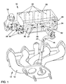
- FIG. 1 shows a suction system part 10 and an exhaust system part 12 with a Exhaust manifold 14 of an internal combustion engine, not otherwise shown, one the exhaust gas recirculation system connecting the exhaust system 12 to the suction system 10 is provided, which comprises the following, one connected to the exhaust manifold 14 Exhaust gas recirculation line 16 and an electrically controlled exhaust gas recirculation valve 18.
- the suction system comprises an upper suction pipe part, only one air collector 20 being shown is, with exit windows 22 to four suction channels shown in Figure 3 and one Inlet window 24 for intake air 26.
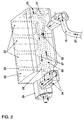
- a first exhaust gas recirculation line part 28 is transverse to the Exit windows 22 provided running, which integrally with the air collector 20th is formed and to which flanged to the air collector 20 via a flange 29 in which Fig. 2, not shown exhaust gas recirculation valve 18 runs.
- Exhaust gas recirculation valve 18 runs away from a second exhaust gas recirculation line part 30, which is also formed in one piece with the air collector 20, to an inlet ramp 32, which avoids acoustic problem and a mixture of returned, cooled exhaust gas 27 with cool intake air 26 ensures. With the exhaust gas recirculation valve 18 are corresponding bores for exhaust gas recirculation by means of sealing caps 34 locked.
Landscapes
- Engineering & Computer Science (AREA)
- Chemical & Material Sciences (AREA)
- Combustion & Propulsion (AREA)
- Mechanical Engineering (AREA)
- General Engineering & Computer Science (AREA)
- Exhaust-Gas Circulating Devices (AREA)
Abstract
Description
- Fig. 1
- eine bevorzugte Ausführungsform eines Sauganlagenteiles und eines Abgasanlagenteiles einer erfindungsgemäßen Brennkraftmaschine als schematisches Drahtmodell und
- Fig. 2
- ein Saugrohroberteil einer erfindungsgemäßen Brennkraftmaschine als schematisches Drahtmodell,
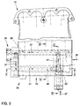
- Fig. 3
- eine Draufsicht auf eine Ausführungsform eines Sauganlagenteiles,
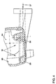
- Fig. 4
- einen Schnitt entlang der Linie IV -IV gemäß Figur 3,
- Fig. 5
- einen Schnitt entlang der Linie V - V gemäß Figur 3 und
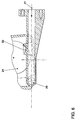
- Fig. 6
- einen Schnitt entlang der Linie VI - VI gemäß Figur 3.
Claims (7)
- Brennkraftmaschine, insbesondere eines Kraftfahrzeuges, mit einer Sauganlage (10) mit Saugrohr zur Verbrennungsluftversorgung und einer Abgasanlage (12), wobei zwischen der Abgasanlage (12) und der Sauganlage (10) eine Abgasrückführungsanlage mit einem Abgasrückführungsventil (18) und einer Abgasrückführungsleitung (16) zur Rückführung von Abgas (27) aus der Abgasanlage (12) an die Sauganlage (10) vorgesehen ist, dadurch gekennzeichnet, daß die Abgasrückführungsleitung (18, 28, 30) wenigstens teilweise in dem Saugrohr verlaufend und in thermischen Kontakt mit Saugluft (26) in dem Saugrohr angeordnet ist.
- Brennkraftmaschine nach Anspruch 1, dadurch gekennzeichnet, daß das Saugrohr einen Luftsammler (20) aufweist, wobei der in dem Saugrohr befindliche Teil (28, 30) der Abgasrückführungsleitung (16) wenigstens teilweise in dem Luftsammler (20) angeordnet ist.
- Brennkraftmaschine nach Anspruch 1 oder 2, dadurch gekennzeichnet, daß die Abgasrückführungsleitung (28, 30) einstückig mit dem Saugrohr ausgebildet ist.
- Brennkraftmaschine nach einem der vorhergehenden Ansprüche, dadurch gekennzeichnet, daß das Abgasrückführungsventil (18) stromab des durch das Saugrohr verlaufenden Teiles (28, 30) der Abgasrückführungsleitung (16) angeordnet ist.
- Brennkraftmaschine nach einem der vorhergehenden Ansprüche, dadurch gekennzeichnet, daß das Abgasrückführungsventil (18) an das Saugrohr, insbesondere an einen Luftsammler (20) des Saugrohres, angeflanscht ist.
- Verfahren zum Rückführen von Abgas bei einer Brennkraftmaschine, insbesondere eines Kraftfahrzeuges, aus einem Abgasstrom in einen Saugluftstrom mit Saugrohr, dadurch gekennzeichnet, daß das rückgeführte Abgas vor einer Einspeisung in den Saugluftstrom derart durch das Saugrohr geführt wird, daß das heiße Abgas Wärme mit dem kühlen Saugluftstrom in dem Saugrohr austauscht.
- Verfahren nach Anspruch 6, dadurch gekennzeichnet, daß das Abgas vor einem Abgasrückführungsventil durch das Saugrohr geführt wird.
Applications Claiming Priority (2)
| Application Number | Priority Date | Filing Date | Title |
|---|---|---|---|
| DE19932792 | 1999-07-14 | ||
| DE19932792A DE19932792A1 (de) | 1999-07-14 | 1999-07-14 | Brennkraftmaschine mit Abgasrückführung und Verfahren zur Abgasrückführung |
Publications (2)
| Publication Number | Publication Date |
|---|---|
| EP1069303A2 true EP1069303A2 (de) | 2001-01-17 |
| EP1069303A3 EP1069303A3 (de) | 2001-09-19 |
Family
ID=7914672
Family Applications (1)
| Application Number | Title | Priority Date | Filing Date |
|---|---|---|---|
| EP00113182A Withdrawn EP1069303A3 (de) | 1999-07-14 | 2000-07-03 | Brennkraftmaschine mit Abgasrückführung und Verfahren zur Abgasrückführung |
Country Status (2)
| Country | Link |
|---|---|
| EP (1) | EP1069303A3 (de) |
| DE (1) | DE19932792A1 (de) |
Families Citing this family (1)
| Publication number | Priority date | Publication date | Assignee | Title |
|---|---|---|---|---|
| KR20150075421A (ko) | 2013-12-17 | 2015-07-06 | 현대자동차주식회사 | 터보차저를 갖는 엔진시스템 |
Citations (3)
| Publication number | Priority date | Publication date | Assignee | Title |
|---|---|---|---|---|
| US3915128A (en) * | 1974-09-16 | 1975-10-28 | Gen Motors Corp | Multi-bore intake manifold with improved fuel distribution |
| US4258687A (en) | 1979-10-09 | 1981-03-31 | Ford Motor Company | Engine with integral mounted EGR cooler |
| DE3518493A1 (de) | 1985-05-23 | 1986-11-27 | Daimler-Benz Ag, 7000 Stuttgart | Abgasrueckfuehrleitung |
Family Cites Families (7)
| Publication number | Priority date | Publication date | Assignee | Title |
|---|---|---|---|---|
| US1342869A (en) * | 1919-11-11 | 1920-06-08 | Ricardo Harry Ralph | Means for heating the charges in internal-combustion engines |
| DE1526519A1 (de) * | 1966-09-02 | |||
| US3667436A (en) * | 1970-01-14 | 1972-06-06 | Robert Reichhelm | Fuel gasification for internal combustion engines |
| DE2650245C2 (de) * | 1976-11-02 | 1986-06-19 | Klöckner-Humboldt-Deutz AG, 5000 Köln | Brennkraftmaschine mit einer Einrichtung zur Vorwärmung der Verbrennungsluft mittels Abgaswärme |
| GB2036175A (en) * | 1978-11-23 | 1980-06-25 | Secretary Industry Brit | Air/fuel mixture vaporizer using exhaust gas heat by direct measuring |
| JPH06288305A (ja) * | 1993-03-31 | 1994-10-11 | Suzuki Motor Corp | エンジンの排気ガス再循環装置 |
| JPH10131813A (ja) * | 1996-10-31 | 1998-05-19 | Suzuki Motor Corp | エンジンのガス分配構造 |
-
1999
- 1999-07-14 DE DE19932792A patent/DE19932792A1/de not_active Withdrawn
-
2000
- 2000-07-03 EP EP00113182A patent/EP1069303A3/de not_active Withdrawn
Patent Citations (3)
| Publication number | Priority date | Publication date | Assignee | Title |
|---|---|---|---|---|
| US3915128A (en) * | 1974-09-16 | 1975-10-28 | Gen Motors Corp | Multi-bore intake manifold with improved fuel distribution |
| US4258687A (en) | 1979-10-09 | 1981-03-31 | Ford Motor Company | Engine with integral mounted EGR cooler |
| DE3518493A1 (de) | 1985-05-23 | 1986-11-27 | Daimler-Benz Ag, 7000 Stuttgart | Abgasrueckfuehrleitung |
Also Published As
| Publication number | Publication date |
|---|---|
| EP1069303A3 (de) | 2001-09-19 |
| DE19932792A1 (de) | 2001-01-18 |
Similar Documents
| Publication | Publication Date | Title |
|---|---|---|
| DE19750588B4 (de) | Vorrichtung zur Abgasrückführung für einen Verbrennungsmotor | |
| DE102015016185B4 (de) | Abgasrückführungssystem für einen Motor | |
| DE102013202834B4 (de) | Einlasssystem mit einem integrierten Ladeluftkühler | |
| DE102012200562A1 (de) | Motorsystem | |
| DE60306954T2 (de) | Verbesserte vorrichtung zur thermischen regelung von der ansaugluft einer brennkraftmaschine und rückgeführtem brennkraftmaschinenabgas | |
| DE102005029322A1 (de) | Vorrichtung zur Rückführung und Kühlung von Abgas für eine Brennkraftmaschine | |
| EP1015750B1 (de) | Anordnung zur rückführung von abgas bei einem verbrennungsmotor | |
| DE102018112800A1 (de) | Kühlmodul für Fahrzeug | |
| DE102007053126A1 (de) | Brennkraftmaschine mit gekühlter Abgasrückführung sowie Abgaskrümmer | |
| DE68905826T2 (de) | Anordnung zum kuehlen der einlassluft fuer turboaufgeladene brennkraftmaschinen. | |
| DE60124004T2 (de) | Anordnung zur kühlung einer leistungsendstufe für einspritzdüsen auf einem einlasskrümmer einer brennkraftmaschine für kraftfahrzeuge | |
| EP0908615A2 (de) | Abgasrückführventil | |
| DE102019210402B4 (de) | Abgasrückführungs-(agr)-kühler und motorsystem mit einem solchen kühler | |
| EP2048345A2 (de) | Wärmetauscher, insbesondere zur Abgaskühlung | |
| EP1069303A2 (de) | Brennkraftmaschine mit Abgasrückführung und Verfahren zur Abgasrückführung | |
| EP0814255B1 (de) | Durch einen Verbrennungsmotor antreibbares Kraftfahrzeug | |
| DE10392766B4 (de) | Abgasleitung für einen Brennkraftmotor mit einer thermischen Regelung der Abgase | |
| EP2886991A1 (de) | Wärmeübertrager | |
| DE102007019089A1 (de) | Abgaswärmetauscher, Abgaswärmetauschersystem, Brennkraftmotor und Verfahren zum Behandeln von Abgasen eines Brennkraftmotors | |
| DE2817486A1 (de) | Aufgeladene brennkraftmaschine | |
| DE102006048527B4 (de) | Kühlkreislauf für eine Brennkraftmaschine | |
| DE19641700C1 (de) | Vorrichtung zur Wärmeübertragung zwischen strömenden Medien für eine Brennkraftmaschine | |
| EP0904483B1 (de) | Kraftfahrzeug mit einer brennkraftmaschine mit äusserer abgasrückführung und heizvorrichtung | |
| DE19814099B4 (de) | Kraftstoff-Leitungssystem bei einem Längsmotor | |
| DE102020208987A1 (de) | Brennkraftmaschine mit zwei Abgasrückführleitungen und einem Abgas-Abgas-Wärmetauscher |
Legal Events
| Date | Code | Title | Description |
|---|---|---|---|
| PUAI | Public reference made under article 153(3) epc to a published international application that has entered the european phase |
Free format text: ORIGINAL CODE: 0009012 |
|
| AK | Designated contracting states |
Kind code of ref document: A2 Designated state(s): AT BE CH CY DE DK ES FI FR GB GR IE IT LI LU MC NL PT SE |
|
| AX | Request for extension of the european patent |
Free format text: AL;LT;LV;MK;RO;SI |
|
| PUAL | Search report despatched |
Free format text: ORIGINAL CODE: 0009013 |
|
| AK | Designated contracting states |
Kind code of ref document: A3 Designated state(s): AT BE CH CY DE DK ES FI FR GB GR IE IT LI LU MC NL PT SE |
|
| AX | Request for extension of the european patent |
Free format text: AL;LT;LV;MK;RO;SI |
|
| 17P | Request for examination filed |
Effective date: 20020319 |
|
| AKX | Designation fees paid |
Free format text: AT BE CH CY DE DK ES FI FR GB GR IE IT LI LU MC NL PT SE |
|
| 17Q | First examination report despatched |
Effective date: 20040212 |
|
| STAA | Information on the status of an ep patent application or granted ep patent |
Free format text: STATUS: THE APPLICATION IS DEEMED TO BE WITHDRAWN |
|
| 18D | Application deemed to be withdrawn |
Effective date: 20041202 |