EP1069303A2 - Combustion engine with exhaust gas recirculation and method of recirculating exhaust gas - Google Patents
Combustion engine with exhaust gas recirculation and method of recirculating exhaust gas Download PDFInfo
- Publication number
- EP1069303A2 EP1069303A2 EP00113182A EP00113182A EP1069303A2 EP 1069303 A2 EP1069303 A2 EP 1069303A2 EP 00113182 A EP00113182 A EP 00113182A EP 00113182 A EP00113182 A EP 00113182A EP 1069303 A2 EP1069303 A2 EP 1069303A2
- Authority
- EP
- European Patent Office
- Prior art keywords
- exhaust gas
- gas recirculation
- intake
- intake manifold
- combustion engine
- Prior art date
- Legal status (The legal status is an assumption and is not a legal conclusion. Google has not performed a legal analysis and makes no representation as to the accuracy of the status listed.)
- Withdrawn
Links
- 238000002485 combustion reaction Methods 0.000 title claims abstract description 20
- 238000000034 method Methods 0.000 title claims description 7
- 230000003134 recirculating effect Effects 0.000 title claims description 3
- 239000002826 coolant Substances 0.000 claims 1
- 238000001816 cooling Methods 0.000 description 7
- 238000009434 installation Methods 0.000 description 4
- 230000001419 dependent effect Effects 0.000 description 2
- 239000000203 mixture Substances 0.000 description 2
- 229910001220 stainless steel Inorganic materials 0.000 description 2
- 239000010935 stainless steel Substances 0.000 description 2
- 230000008646 thermal stress Effects 0.000 description 2
- 230000000694 effects Effects 0.000 description 1
- 238000010438 heat treatment Methods 0.000 description 1
- 230000005855 radiation Effects 0.000 description 1
- 238000007789 sealing Methods 0.000 description 1
- 239000013585 weight reducing agent Substances 0.000 description 1
Images

Classifications
-
- F—MECHANICAL ENGINEERING; LIGHTING; HEATING; WEAPONS; BLASTING
- F02—COMBUSTION ENGINES; HOT-GAS OR COMBUSTION-PRODUCT ENGINE PLANTS
- F02M—SUPPLYING COMBUSTION ENGINES IN GENERAL WITH COMBUSTIBLE MIXTURES OR CONSTITUENTS THEREOF
- F02M35/00—Combustion-air cleaners, air intakes, intake silencers, or induction systems specially adapted for, or arranged on, internal-combustion engines
- F02M35/10—Air intakes; Induction systems
- F02M35/10209—Fluid connections to the air intake system; their arrangement of pipes, valves or the like
- F02M35/10222—Exhaust gas recirculation [EGR]; Positive crankcase ventilation [PCV]; Additional air admission, lubricant or fuel vapour admission
-
- F—MECHANICAL ENGINEERING; LIGHTING; HEATING; WEAPONS; BLASTING
- F02—COMBUSTION ENGINES; HOT-GAS OR COMBUSTION-PRODUCT ENGINE PLANTS
- F02M—SUPPLYING COMBUSTION ENGINES IN GENERAL WITH COMBUSTIBLE MIXTURES OR CONSTITUENTS THEREOF
- F02M26/00—Engine-pertinent apparatus for adding exhaust gases to combustion-air, main fuel or fuel-air mixture, e.g. by exhaust gas recirculation [EGR] systems
- F02M26/13—Arrangement or layout of EGR passages, e.g. in relation to specific engine parts or for incorporation of accessories
- F02M26/17—Arrangement or layout of EGR passages, e.g. in relation to specific engine parts or for incorporation of accessories in relation to the intake system
-
- F—MECHANICAL ENGINEERING; LIGHTING; HEATING; WEAPONS; BLASTING
- F02—COMBUSTION ENGINES; HOT-GAS OR COMBUSTION-PRODUCT ENGINE PLANTS
- F02M—SUPPLYING COMBUSTION ENGINES IN GENERAL WITH COMBUSTIBLE MIXTURES OR CONSTITUENTS THEREOF
- F02M26/00—Engine-pertinent apparatus for adding exhaust gases to combustion-air, main fuel or fuel-air mixture, e.g. by exhaust gas recirculation [EGR] systems
- F02M26/13—Arrangement or layout of EGR passages, e.g. in relation to specific engine parts or for incorporation of accessories
- F02M26/22—Arrangement or layout of EGR passages, e.g. in relation to specific engine parts or for incorporation of accessories with coolers in the recirculation passage
- F02M26/29—Constructional details of the coolers, e.g. pipes, plates, ribs, insulation or materials
- F02M26/30—Connections of coolers to other devices, e.g. to valves, heaters, compressors or filters; Coolers characterised by their location on the engine
-
- F—MECHANICAL ENGINEERING; LIGHTING; HEATING; WEAPONS; BLASTING
- F02—COMBUSTION ENGINES; HOT-GAS OR COMBUSTION-PRODUCT ENGINE PLANTS
- F02M—SUPPLYING COMBUSTION ENGINES IN GENERAL WITH COMBUSTIBLE MIXTURES OR CONSTITUENTS THEREOF
- F02M26/00—Engine-pertinent apparatus for adding exhaust gases to combustion-air, main fuel or fuel-air mixture, e.g. by exhaust gas recirculation [EGR] systems
- F02M26/13—Arrangement or layout of EGR passages, e.g. in relation to specific engine parts or for incorporation of accessories
- F02M26/22—Arrangement or layout of EGR passages, e.g. in relation to specific engine parts or for incorporation of accessories with coolers in the recirculation passage
- F02M26/29—Constructional details of the coolers, e.g. pipes, plates, ribs, insulation or materials
- F02M26/31—Air-cooled heat exchangers
-
- F—MECHANICAL ENGINEERING; LIGHTING; HEATING; WEAPONS; BLASTING
- F02—COMBUSTION ENGINES; HOT-GAS OR COMBUSTION-PRODUCT ENGINE PLANTS
- F02M—SUPPLYING COMBUSTION ENGINES IN GENERAL WITH COMBUSTIBLE MIXTURES OR CONSTITUENTS THEREOF
- F02M26/00—Engine-pertinent apparatus for adding exhaust gases to combustion-air, main fuel or fuel-air mixture, e.g. by exhaust gas recirculation [EGR] systems
- F02M26/13—Arrangement or layout of EGR passages, e.g. in relation to specific engine parts or for incorporation of accessories
- F02M26/41—Arrangement or layout of EGR passages, e.g. in relation to specific engine parts or for incorporation of accessories characterised by the arrangement of the recirculation passage in relation to the engine, e.g. to cylinder heads, liners, spark plugs or manifolds; characterised by the arrangement of the recirculation passage in relation to specially adapted combustion chambers
-
- F—MECHANICAL ENGINEERING; LIGHTING; HEATING; WEAPONS; BLASTING
- F02—COMBUSTION ENGINES; HOT-GAS OR COMBUSTION-PRODUCT ENGINE PLANTS
- F02M—SUPPLYING COMBUSTION ENGINES IN GENERAL WITH COMBUSTIBLE MIXTURES OR CONSTITUENTS THEREOF
- F02M31/00—Apparatus for thermally treating combustion-air, fuel, or fuel-air mixture
- F02M31/02—Apparatus for thermally treating combustion-air, fuel, or fuel-air mixture for heating
- F02M31/04—Apparatus for thermally treating combustion-air, fuel, or fuel-air mixture for heating combustion-air or fuel-air mixture
- F02M31/06—Apparatus for thermally treating combustion-air, fuel, or fuel-air mixture for heating combustion-air or fuel-air mixture by hot gases, e.g. by mixing cold and hot air
- F02M31/08—Apparatus for thermally treating combustion-air, fuel, or fuel-air mixture for heating combustion-air or fuel-air mixture by hot gases, e.g. by mixing cold and hot air the gases being exhaust gases
-
- F—MECHANICAL ENGINEERING; LIGHTING; HEATING; WEAPONS; BLASTING
- F02—COMBUSTION ENGINES; HOT-GAS OR COMBUSTION-PRODUCT ENGINE PLANTS
- F02M—SUPPLYING COMBUSTION ENGINES IN GENERAL WITH COMBUSTIBLE MIXTURES OR CONSTITUENTS THEREOF
- F02M35/00—Combustion-air cleaners, air intakes, intake silencers, or induction systems specially adapted for, or arranged on, internal-combustion engines
- F02M35/10—Air intakes; Induction systems
- F02M35/10006—Air intakes; Induction systems characterised by the position of elements of the air intake system in direction of the air intake flow, i.e. between ambient air inlet and supply to the combustion chamber
- F02M35/10026—Plenum chambers
-
- Y—GENERAL TAGGING OF NEW TECHNOLOGICAL DEVELOPMENTS; GENERAL TAGGING OF CROSS-SECTIONAL TECHNOLOGIES SPANNING OVER SEVERAL SECTIONS OF THE IPC; TECHNICAL SUBJECTS COVERED BY FORMER USPC CROSS-REFERENCE ART COLLECTIONS [XRACs] AND DIGESTS
- Y02—TECHNOLOGIES OR APPLICATIONS FOR MITIGATION OR ADAPTATION AGAINST CLIMATE CHANGE
- Y02T—CLIMATE CHANGE MITIGATION TECHNOLOGIES RELATED TO TRANSPORTATION
- Y02T10/00—Road transport of goods or passengers
- Y02T10/10—Internal combustion engine [ICE] based vehicles
- Y02T10/12—Improving ICE efficiencies
Definitions
- the invention relates to an internal combustion engine with an intake system with an intake manifold Combustion air supply and an exhaust system, being between the exhaust system and the intake system an exhaust gas recirculation system with an exhaust gas recirculation valve and an exhaust gas recirculation line for returning exhaust gas from the exhaust system to the Suction system is provided, according to the preamble of claim 1.
- the invention relates a method for recirculating exhaust gas in an internal combustion engine from a Exhaust gas flow in a suction air flow with an intake manifold, according to the preamble of claim 6.
- EGR or EGR E xhaust G as R ecirculation
- part of the exhaust gas is removed shortly behind the exhaust manifold and mixed with the intake air in the intake pipe via an EGR valve and thus returned to the engine.
- this arrangement is complex, expensive and requires a large amount of installation space, which is why the realization is proposed for a V engine, where there is excess installation space in the valley of the V-shaped arrangement of the cylinders, which is filled by the EGR cooler.
- the present invention is therefore based on the object of an improved Internal combustion engine and an improved method of the above type are available.
- the above disadvantages are overcome and simple, Inexpensive and requires little space with an exhaust gas recirculation in particular reduced thermal load on the exhaust gas recirculation valve is achieved.
- the suction pipe has an air collector, the part of the exhaust gas recirculation line located in the intake manifold is at least partially in the Air collector is arranged.
- a further reduction in the installation space requirement is achieved with simple assembly at the same time one in that the exhaust gas recirculation line is formed in one piece with the intake manifold is.
- the exhaust gas recirculation valve is on the intake manifold, in particular flanged to an air collector of the intake manifold.
- the exhaust gas is expediently passed through the intake manifold in front of an exhaust gas recirculation valve performed so that there is a reduced thermal load on the exhaust gas recirculation valve results.
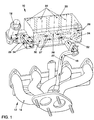
- FIG. 1 shows a suction system part 10 and an exhaust system part 12 with a Exhaust manifold 14 of an internal combustion engine, not otherwise shown, one the exhaust gas recirculation system connecting the exhaust system 12 to the suction system 10 is provided, which comprises the following, one connected to the exhaust manifold 14 Exhaust gas recirculation line 16 and an electrically controlled exhaust gas recirculation valve 18.
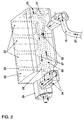
- the suction system comprises an upper suction pipe part, only one air collector 20 being shown is, with exit windows 22 to four suction channels shown in Figure 3 and one Inlet window 24 for intake air 26.
- a first exhaust gas recirculation line part 28 is transverse to the Exit windows 22 provided running, which integrally with the air collector 20th is formed and to which flanged to the air collector 20 via a flange 29 in which Fig. 2, not shown exhaust gas recirculation valve 18 runs.
- Exhaust gas recirculation valve 18 runs away from a second exhaust gas recirculation line part 30, which is also formed in one piece with the air collector 20, to an inlet ramp 32, which avoids acoustic problem and a mixture of returned, cooled exhaust gas 27 with cool intake air 26 ensures. With the exhaust gas recirculation valve 18 are corresponding bores for exhaust gas recirculation by means of sealing caps 34 locked.
Landscapes
- Engineering & Computer Science (AREA)
- Chemical & Material Sciences (AREA)
- Combustion & Propulsion (AREA)
- Mechanical Engineering (AREA)
- General Engineering & Computer Science (AREA)
- Exhaust-Gas Circulating Devices (AREA)
Abstract
Die Erfindung betrifft eine Brennkraftmaschine, insbesondere eines Kraftfahrzeuges, mit einer Sauganlage (10) mit Saugrohr zur Verbrennungsluftversorgung und einer Abgasanlage (12), wobei zwischen der Abgasanlage (12) und der Sauganlage (10) eine Abgasrückführungsanlage mit einem Abgasrückführungsventil (18) und einer Abgasrückführungsleitung (16) zur Rückführung von Abgas (27) aus der Abgasanlage (12) an die Sauganlage (10) vorgesehen ist. Hierbei ist die Abgasrückführungsleitung (18, 28, 30) wenigstens teilweise in dem Saugrohr verlaufend und in thermischen Kontakt mit Saugluft (26) in dem Saugrohr angeordnet. <IMAGE>The invention relates to an internal combustion engine, in particular a motor vehicle, having an intake system (10) with an intake manifold for supplying combustion air and an exhaust system (12), an exhaust gas recirculation system with an exhaust gas recirculation valve (18) and one between the exhaust system (12) and the intake system (10) Exhaust gas recirculation line (16) for returning exhaust gas (27) from the exhaust system (12) to the intake system (10) is provided. The exhaust gas recirculation line (18, 28, 30) runs at least partially in the intake manifold and is arranged in thermal contact with intake air (26) in the intake manifold. <IMAGE>
Description
Die Erfindung betrifft ein Brennkraftmaschine mit einer Sauganlage mit Saugrohr zur Verbrennungsluftversorgung und einer Abgasanlage, wobei zwischen der Abgasanlage und der Sauganlage eine Abgasrückführungsanlage mit einem Abgasrückführungsventil und einer Abgasrückführungsleitung zur Rückführung von Abgas aus der Abgasanlage an die Sauganlage vorgesehen ist, gemäß dem Oberbegriff des Anspruchs 1. Die Erfindung betrifft ferner ein Verfahren zum Rückführen von Abgas bei einer Brennkraftmaschine aus einem Abgasstrom in einen Saugluftstrom mit Saugrohr, gemäß dem Oberbegriff des Anspruchs 6.The invention relates to an internal combustion engine with an intake system with an intake manifold Combustion air supply and an exhaust system, being between the exhaust system and the intake system an exhaust gas recirculation system with an exhaust gas recirculation valve and an exhaust gas recirculation line for returning exhaust gas from the exhaust system to the Suction system is provided, according to the preamble of claim 1. The invention relates a method for recirculating exhaust gas in an internal combustion engine from a Exhaust gas flow in a suction air flow with an intake manifold, according to the preamble of claim 6.
Bei der Abgasrückführung (AGR oder EGR = Exhaust Gas Recirculation) wird ein Teil des Abgases kurz hinter dem Abgaskrümmer entnommen und der Ansaugluft im Ansaugrohr über ein EGR-Ventil wieder beigemischt und damit dem Motor zurückgeführt. Wegen der begrenzten thermischen Belastbarkeit von Bauteilen in dem EGR-Ventil, wie beispielsweise Spulen einer elektrischen Ventilbetätigung, die Temperaturen von maximal 180°C bis 230°C widerstehen, ist es erforderlich, das heiße Abgas vor dem Durchlauf durch das EGR-Ventil zu kühlen. Hierzu ist es beispielsweise aus der US 4 258 687 bekannt, an der Unterseite einer Ansaugverrohrung einen wassergekühlten EGR-Kühler vorzusehen. Diese Anordnung ist jedoch aufwendig, teuer und benötigt viel Bauraum, weshalb die Realisation bei einem V-Motor vorgeschlagen wird, wo sich im Tal der V-förmigen Anordnung der Zylinder überschüssiger Bauraum befindet, der durch den EGR-Kühler ausgefüllt wird.With exhaust gas recirculation (EGR or EGR = E xhaust G as R ecirculation), part of the exhaust gas is removed shortly behind the exhaust manifold and mixed with the intake air in the intake pipe via an EGR valve and thus returned to the engine. Due to the limited thermal load capacity of components in the EGR valve, such as coils of an electrical valve actuation that can withstand temperatures of a maximum of 180 ° C. to 230 ° C., it is necessary to cool the hot exhaust gas before it passes through the EGR valve . For this purpose, it is known, for example, from US Pat. No. 4,258,687 to provide a water-cooled EGR cooler on the underside of an intake pipe. However, this arrangement is complex, expensive and requires a large amount of installation space, which is why the realization is proposed for a V engine, where there is excess installation space in the valley of the V-shaped arrangement of the cylinders, which is filled by the EGR cooler.
Aus der DE 35 18 493 C2 ist es bekannt, einen Teil einer Abgasrückführungsleitung parallel zu einer Warmluftansaugleitung anzuordnen, welche am Abgaskrümmer vorbeiströmende und damit vorgewärmte Luft ansaugt, so daß durch einen Wärmeaustausch zwischen der Ansaugluft in der Warmluftansaugleitung und der Abgasrückführungsleitung die Ansaugluft in der Warmluftansaugleitung zusätzlich erwärmt und gleichzeitig Nebenaggregate vor Wärmeabstrahlung der Abgasruckführungsleitung geschützt sind. Das EGR-Ventil befindet sich jedoch nahe am Abgaskrümmer und hat aufgrund hoher thermischer Belastung nur eine begrenzte Lebensdauer. From DE 35 18 493 C2 it is known to parallel part of an exhaust gas recirculation line to arrange a warm air intake pipe, which flows past the exhaust manifold and thus sucks in preheated air, so that through a heat exchange between the Intake air in the warm air intake line and the exhaust gas recirculation line the intake air in the warm air intake pipe additionally heated and at the same time auxiliary units Heat radiation from the exhaust gas recirculation line are protected. The EGR valve is located but close to the exhaust manifold and has only one due to high thermal stress limited life.
Der vorliegenden Erfindung liegt daher die Aufgabe zugrunde, eine verbesserte Brennkraftmaschine sowie ein verbesserte Verfahren der obengenannten Art zur Verfügung zu stellen, wobei die obengenannten Nachteile überwunden werden und auf einfache, kostengünstige und wenig Bauraum benötigende Weise eine Abgasrückführung mit insbesondere reduzierter thermischer Belastung des Abgasrückführungsventils erzielt wird.The present invention is therefore based on the object of an improved Internal combustion engine and an improved method of the above type are available The above disadvantages are overcome and simple, Inexpensive and requires little space with an exhaust gas recirculation in particular reduced thermal load on the exhaust gas recirculation valve is achieved.
Diese Aufgabe wird erfindungsgemäß durch eine Brennkraftmaschine der o.g. Art mit den in Anspruch 1 gekennzeichneten Merkmalen und durch ein Verfahren der o.g. Art mit den in Anspruch 6 gekennzeichneten Merkmalen gelöst. Vorteilhafte Ausgestaltungen der Erfindung sind in den abhängigen Ansprüchen angegeben.This object is achieved by an internal combustion engine of the above. Kind of with the in Characteristic characterized in claim 1 and by a method of the above. Kind of with the in Characteristic characterized 6 solved. Advantageous embodiments of the invention are specified in the dependent claims.
Dazu ist es bei einer Brennkraftmaschine der o.g Art erfindungsgemäß vorgesehen, daß die Abgasrückführungsleitung wenigstens teilweise in dem Saugrohr verlaufend und in thermischen Kontakt mit Saugluft in dem Saugrohr angeordnet ist.For this purpose, it is provided according to the invention in an internal combustion engine of the above type that the Exhaust gas recirculation line at least partially in the intake manifold and in thermal contact with suction air is arranged in the suction pipe.
Dies hat den Vorteil, daß eine Kühlung des rückgeführten Abgases ohne zusätzlichen Abgasluftkühler erfolgt, wobei durch die Integration der Kühlfunktion in das Saugrohr ein minimaler Bauraum erforderlich ist.This has the advantage that cooling of the recirculated exhaust gas without additional Exhaust air cooler takes place by integrating the cooling function into the intake manifold minimal space is required.
In einer bevorzugten Ausführungsform weist das Saugrohr einen Luftsammler auf, wobei der in dem Saugrohr befindliche Teil der Abgasrückführungsleitung wenigstens teilweise in dem Luftsammler angeordnet ist.In a preferred embodiment, the suction pipe has an air collector, the part of the exhaust gas recirculation line located in the intake manifold is at least partially in the Air collector is arranged.
Eine weitere Reduzierung des Bauraumbedarfs bei gleichzeitig einfacher Montage erzielt man dadurch, daß die Abgasrückführungsleitung einstückig mit dem Saugrohr ausgebildet ist.A further reduction in the installation space requirement is achieved with simple assembly at the same time one in that the exhaust gas recirculation line is formed in one piece with the intake manifold is.
Zum Vermindern einer thermischen Belastung des Abgasrückführungsventils ist dieses stromab des durch das Saugrohr verlaufenden Teiles der Abgasrückführungsleitung angeordnet.This is to reduce thermal stress on the exhaust gas recirculation valve downstream of the part of the exhaust gas recirculation line running through the intake manifold arranged.
In einer bevorzugten Ausführungsform ist das Abgasrückführungsventil an das Saugrohr, insbesondere an einen Luftsammler des Saugrohres, angeflanscht. In a preferred embodiment, the exhaust gas recirculation valve is on the intake manifold, in particular flanged to an air collector of the intake manifold.
Bei einem Verfahren der o.g. Art ist es erfindungsgemäß vorgesehen, daß das rückgeführte Abgas vor einer Einspeisung in den Saugluftstrom derart durch das Saugrohr geführt wird, daß das heiße Abgas Wärme mit dem kühlen Saugluftstrom in dem Saugrohr austauscht.In a procedure of the above Art is provided according to the invention that the returned Exhaust gas is fed through the intake manifold before being fed into the suction air flow, that the hot exhaust gas exchanges heat with the cool suction air flow in the intake manifold.
Dies hat den Vorteil, daß auf einfache und effektive Weise eine Kühlung des rückgeführten Abgases und erzielt wird.This has the advantage that cooling of the recirculated is simple and effective Exhaust gas and is achieved.
Zweckmäßigerweise wird das Abgas vor einem Abgasrückführungsventil durch das Saugrohr geführt, so daß sich eine reduzierte thermische Belastung des Abgasrückführungsventils ergibt.The exhaust gas is expediently passed through the intake manifold in front of an exhaust gas recirculation valve performed so that there is a reduced thermal load on the exhaust gas recirculation valve results.
Weitere Merkmale, Vorteile und vorteilhafte Ausgestaltungen der Erfindung ergeben sich aus den abhängigen Ansprüchen, sowie aus der nachstehenden Beschreibung der Erfindung anhand der beigefügten Zeichnungen. Diese zeigen in
- Fig. 1
- eine bevorzugte Ausführungsform eines Sauganlagenteiles und eines Abgasanlagenteiles einer erfindungsgemäßen Brennkraftmaschine als schematisches Drahtmodell und
- Fig. 2
- ein Saugrohroberteil einer erfindungsgemäßen Brennkraftmaschine als schematisches Drahtmodell,
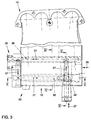
- Fig. 3
- eine Draufsicht auf eine Ausführungsform eines Sauganlagenteiles,
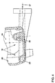
- Fig. 4
- einen Schnitt entlang der Linie IV -IV gemäß Figur 3,
- Fig. 5
- einen Schnitt entlang der Linie V - V gemäß Figur 3 und
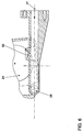
- Fig. 6
- einen Schnitt entlang der Linie VI - VI gemäß Figur 3.
- Fig. 1
- a preferred embodiment of a suction system part and an exhaust system part of an internal combustion engine according to the invention as a schematic wire model and
- Fig. 2
- an intake manifold upper part of an internal combustion engine according to the invention as a schematic wire model,
- Fig. 3
- a plan view of an embodiment of a suction system part,
- Fig. 4
- 4 shows a section along the line IV-IV according to FIG. 3,
- Fig. 5
- a section along the line V - V according to Figure 3 and
- Fig. 6
- a section along the line VI - VI of Figure 3.
Fig. 1 zeigt einen Sauganlagenteil 10 und einen Abgasanlagenteil 12 mit einem
Abgaskrümmer 14 einer ansonsten nicht näher dargestellten Brennkraftmaschine, wobei eine
die Abgasanlage 12 mit der Sauganlage 10 verbindende Abgasrückführungsanlage
vorgesehen ist, welche folgendes umfaßt, eine mit dem Abgaskrümmer 14 verbundene
Abgasrückführungsleitung 16 und ein elektrisch angesteuertes Abgasrückführungsventil 18.
Die Sauganlage umfaßt ein Saugrohroberteil, wobei lediglich ein Luftsammler 20 dargestellt
ist, mit Austrittsfenstern 22 zu vier in Figur 3 dargestellten Saugkanälen und einem
Eintrittsfenster 24 für Ansaugluft 26.1 shows a
Wie im Detail z. B. aus Figuren 2 und 4 ersichtlich, verläuft ein Teil der
Abgasrückführungsleitung 16 innerhalb des Luftsammlers 20 und in thermischen Kontakt mit
Ansaugluft 26, so daß letztere das in der Abgasrückführungsleitung 16 rückgeführte Abgas
27 abkühlt. Hierbei ist ein erster Abgasrückführungsleitungsteil 28 quer zu den
Austrittsfenstern 22 verlaufend vorgesehen, welcher einstückig mit dem Luftsammler 20
ausgebildet ist und zu dem am Luftsammler 20 über einen Flansch 29angeflanschten, in der
Fig. 2 nicht dargestellten Abgasrückführungsventil 18 verläuft. Von dem
Abgasrückführungsventil 18 weg verläuft ein zweiter Abgasrückführungsleitungsteil 30,
welcher ebenfalls einstückig mit dem Luftsammler 20 ausgebildet ist, zu einer Einlauframpe
32, welche akustische Problem vermeidet und eine Vermischung von rückgeführtem,
gekühltem Abgas 27 mit kühler Ansaugluft 26 sicherstellt. Bei dem Abgasrückführungsventil
18 sind entsprechende Bohrungen für die Abgasrückführung mittels Verschlußdeckeln 34
verschlossen.As in detail e.g. B. from Figures 2 and 4, part of the
Exhaust
Durch den thermischen Kontakt und einen entsprechenden Wärmeübergang von dem
heißen, rückgeführten Abgas 27 zu der kühlen Ansaugluft 26 innerhalb des Luftsammlers 20
wird eine ausreichende Kühlung des rückgeführten Abgases erzielt, so daß eine thermische
Belastung des Abgasrückführungsventils 18 entsprechend reduziert ist und damit das
Abgasrückführungsventil 18 dementsprechend kostengünstiger ausgeführt sein kann, da es
nicht mehr für hohe Abgastemperaturen ausgelegt sein muß.Due to the thermal contact and a corresponding heat transfer from the
hot, recirculated
Wie insbesondere aus Fig. 1 ersichtlich, kann die Anbindung zwischen Abgasanlage und
Sauganlage über ein kurze Abgasrückführungsleitung 16 erfolgen, so daß sich eine
verringerte thermische Belastung eines Motorraumes in einem Kraftfahrzeug ergibt. Dies
erzielt eine schwingungsarme Anbindung mit geringen Montagekosten. Da ferner die
Abführung der Wärmeenergie des rückgeführten Abgases ständig durch die Ansaugluft
erfolgt, erniedrigt sich dementsprechend eine Temperatur im Motorraum. Der geringe
Bauraumbedarf der erfindungsgemäßen Lösung zur Abgasrückführung erzielt ferner eine
entsprechende Gewichtsreduzierung, da weniger Bauteil notwendig sind.As can be seen in particular from FIG. 1, the connection between the exhaust system and
Suction system via a short exhaust
Durch die ständig von der Ansaugluft 26 umströmten Abgasrückführungsleitungsteile 28 und
30 ergibt sich eine effizientere Kühlung. Da die Bestandteile des Saugrohres, üblicherweise
Al bzw. Mg, einen etwa zehnmal höheren Wärmeleitkoeffizienten als Edelstahl aufweisen,
ergibt sich ein besserer Wärmeübergang und damit eine bessere Abkühlung des
rückgeführten Abgases 27 als bei herkömmlichen Abgasrückführungssystemen, welche eine
Abgaskühlung lediglich in einem externen, aus Edelstahl gefertigten Rückführungsrohr
vorsehen.Due to the exhaust gas
Überraschenderweise tritt keine negative Beeinflussung der Beladung der Zylinder und der
Klopfgrenze durch die direkte Erwärmung der Ansaugluft in dem Saugrohr bzw. im
Luftsammler 20 des Saugrohres und damit durch die Erhöhung der Ansauglufttemperatur
insbesondere im Teillastbereich auf. Der Grund hierfür könnte u.a. dann liegen, daß sich die
Abgaseinspeisung negativ auf die Entflammbarkeit des noch nicht entzündeten Kraftstoff-Luft-Gemisches
in einer Brennkammer und somit im Vergleich zur Erhöhung der
Ansauglufttemperatur positiv entgegengesetzt auf die Klopfgrenze auswirkt.Surprisingly, there is no negative influence on the loading of the cylinders and the
Knock limit due to the direct heating of the intake air in the intake manifold or in the
Claims (7)
Applications Claiming Priority (2)
| Application Number | Priority Date | Filing Date | Title |
|---|---|---|---|
| DE19932792A DE19932792A1 (en) | 1999-07-14 | 1999-07-14 | Internal combustion engine with exhaust gas recirculation and method for exhaust gas recirculation |
| DE19932792 | 1999-07-14 |
Publications (2)
| Publication Number | Publication Date |
|---|---|
| EP1069303A2 true EP1069303A2 (en) | 2001-01-17 |
| EP1069303A3 EP1069303A3 (en) | 2001-09-19 |
Family
ID=7914672
Family Applications (1)
| Application Number | Title | Priority Date | Filing Date |
|---|---|---|---|
| EP00113182A Withdrawn EP1069303A3 (en) | 1999-07-14 | 2000-07-03 | Combustion engine with exhaust gas recirculation and method of recirculating exhaust gas |
Country Status (2)
| Country | Link |
|---|---|
| EP (1) | EP1069303A3 (en) |
| DE (1) | DE19932792A1 (en) |
Families Citing this family (1)
| Publication number | Priority date | Publication date | Assignee | Title |
|---|---|---|---|---|
| KR20150075421A (en) | 2013-12-17 | 2015-07-06 | 현대자동차주식회사 | Engine system having turbo charger |
Citations (3)
| Publication number | Priority date | Publication date | Assignee | Title |
|---|---|---|---|---|
| US3915128A (en) * | 1974-09-16 | 1975-10-28 | Gen Motors Corp | Multi-bore intake manifold with improved fuel distribution |
| US4258687A (en) | 1979-10-09 | 1981-03-31 | Ford Motor Company | Engine with integral mounted EGR cooler |
| DE3518493A1 (en) | 1985-05-23 | 1986-11-27 | Daimler-Benz Ag, 7000 Stuttgart | Exhaust gas recirculation pipe |
Family Cites Families (7)
| Publication number | Priority date | Publication date | Assignee | Title |
|---|---|---|---|---|
| US1342869A (en) * | 1919-11-11 | 1920-06-08 | Ricardo Harry Ralph | Means for heating the charges in internal-combustion engines |
| DE1526519A1 (en) * | 1966-09-02 | |||
| US3667436A (en) * | 1970-01-14 | 1972-06-06 | Robert Reichhelm | Fuel gasification for internal combustion engines |
| DE2650245C2 (en) * | 1976-11-02 | 1986-06-19 | Klöckner-Humboldt-Deutz AG, 5000 Köln | Internal combustion engine with a device for preheating the combustion air by means of exhaust gas heat |
| GB2036175A (en) * | 1978-11-23 | 1980-06-25 | Secretary Industry Brit | Air/fuel mixture vaporizer using exhaust gas heat by direct measuring |
| JPH06288305A (en) * | 1993-03-31 | 1994-10-11 | Suzuki Motor Corp | Engine exhaust gas recirculation system |
| JPH10131813A (en) * | 1996-10-31 | 1998-05-19 | Suzuki Motor Corp | Engine gas distribution structure |
-
1999
- 1999-07-14 DE DE19932792A patent/DE19932792A1/en not_active Withdrawn
-
2000
- 2000-07-03 EP EP00113182A patent/EP1069303A3/en not_active Withdrawn
Patent Citations (3)
| Publication number | Priority date | Publication date | Assignee | Title |
|---|---|---|---|---|
| US3915128A (en) * | 1974-09-16 | 1975-10-28 | Gen Motors Corp | Multi-bore intake manifold with improved fuel distribution |
| US4258687A (en) | 1979-10-09 | 1981-03-31 | Ford Motor Company | Engine with integral mounted EGR cooler |
| DE3518493A1 (en) | 1985-05-23 | 1986-11-27 | Daimler-Benz Ag, 7000 Stuttgart | Exhaust gas recirculation pipe |
Also Published As
| Publication number | Publication date |
|---|---|
| DE19932792A1 (en) | 2001-01-18 |
| EP1069303A3 (en) | 2001-09-19 |
Similar Documents
| Publication | Publication Date | Title |
|---|---|---|
| EP0916837B1 (en) | Exhaust gas recirculating device for a combustion engine | |
| DE102015016185B4 (en) | Exhaust gas recirculation system for an engine | |
| DE102013202834B4 (en) | Intake system with an integrated intercooler | |
| DE102012200562A1 (en) | engine system | |
| DE102007053126B4 (en) | Internal combustion engine with cooled exhaust gas recirculation and exhaust manifold | |
| DE102005029322A1 (en) | Device for recycling and cooling exhaust gas for an internal combustion engine | |
| EP1015750B1 (en) | System for recirculating exhaust gas in an internal combustion engine | |
| DE102018112800A1 (en) | Cooling module for vehicle | |
| DE60124004T2 (en) | ARRANGEMENT FOR COOLING A PERFORMANCE END OF INJECTION NOZZLES ON AN INTAKE MANIFOLD OF AN INTERNAL COMBUSTION ENGINE FOR A MOTOR VEHICLE | |
| EP0908615A2 (en) | Exhaust gas recirculation valve | |
| EP2048345B1 (en) | Heat exchanger, in particular for cooling exhaust gas | |
| DE102019210402A1 (en) | EGR COOLER AND ENGINE SYSTEM WITH SUCH A COOLER | |
| EP1069303A2 (en) | Combustion engine with exhaust gas recirculation and method of recirculating exhaust gas | |
| EP0814255B1 (en) | Vehicle driven by an internal combustion engine | |
| DE10392766B4 (en) | Exhaust pipe for an internal combustion engine with a thermal control of the exhaust gases | |
| EP2886991A1 (en) | Heat exchanger | |
| DE19735306B4 (en) | Internal combustion engine | |
| DE102007019089A1 (en) | Exhaust gas heat exchanger, exhaust gas heat exchanger system, internal combustion engine and method for treating exhaust gases of an internal combustion engine | |
| DE2817486A1 (en) | CHARGED COMBUSTION ENGINE | |
| DE102006048527B4 (en) | Cooling circuit for an internal combustion engine | |
| DE19641700C1 (en) | Multiple heat-exchanger used in internal combustion engine | |
| EP0904483B1 (en) | Motor vehicle with an internal combustion engine with external exhaust gas recirculation system and heater | |
| DE19814099B4 (en) | Fuel line system in a longitudinal engine | |
| DE102019206450B4 (en) | Engine system | |
| DE102020208987A1 (en) | Internal combustion engine with two exhaust gas recirculation lines and an exhaust gas/exhaust gas heat exchanger |
Legal Events
| Date | Code | Title | Description |
|---|---|---|---|
| PUAI | Public reference made under article 153(3) epc to a published international application that has entered the european phase |
Free format text: ORIGINAL CODE: 0009012 |
|
| AK | Designated contracting states |
Kind code of ref document: A2 Designated state(s): AT BE CH CY DE DK ES FI FR GB GR IE IT LI LU MC NL PT SE |
|
| AX | Request for extension of the european patent |
Free format text: AL;LT;LV;MK;RO;SI |
|
| PUAL | Search report despatched |
Free format text: ORIGINAL CODE: 0009013 |
|
| AK | Designated contracting states |
Kind code of ref document: A3 Designated state(s): AT BE CH CY DE DK ES FI FR GB GR IE IT LI LU MC NL PT SE |
|
| AX | Request for extension of the european patent |
Free format text: AL;LT;LV;MK;RO;SI |
|
| 17P | Request for examination filed |
Effective date: 20020319 |
|
| AKX | Designation fees paid |
Free format text: AT BE CH CY DE DK ES FI FR GB GR IE IT LI LU MC NL PT SE |
|
| 17Q | First examination report despatched |
Effective date: 20040212 |
|
| STAA | Information on the status of an ep patent application or granted ep patent |
Free format text: STATUS: THE APPLICATION IS DEEMED TO BE WITHDRAWN |
|
| 18D | Application deemed to be withdrawn |
Effective date: 20041202 |