EP1069229B1 - Device to hold the button strip of a shirt - Google Patents
Device to hold the button strip of a shirt Download PDFInfo
- Publication number
- EP1069229B1 EP1069229B1 EP00114544A EP00114544A EP1069229B1 EP 1069229 B1 EP1069229 B1 EP 1069229B1 EP 00114544 A EP00114544 A EP 00114544A EP 00114544 A EP00114544 A EP 00114544A EP 1069229 B1 EP1069229 B1 EP 1069229B1
- Authority
- EP
- European Patent Office
- Prior art keywords
- fixing elements
- button
- buttonhole
- fixing
- strip
- Prior art date
- Legal status (The legal status is an assumption and is not a legal conclusion. Google has not performed a legal analysis and makes no representation as to the accuracy of the status listed.)
- Expired - Lifetime
Links
Images
Classifications
-
- D—TEXTILES; PAPER
- D06—TREATMENT OF TEXTILES OR THE LIKE; LAUNDERING; FLEXIBLE MATERIALS NOT OTHERWISE PROVIDED FOR
- D06F—LAUNDERING, DRYING, IRONING, PRESSING OR FOLDING TEXTILE ARTICLES
- D06F71/00—Apparatus for hot-pressing clothes, linen or other textile articles, i.e. wherein there is substantially no relative movement between pressing element and article while pressure is being applied to the article; Similar machines for cold-pressing clothes, linen or other textile articles
- D06F71/32—Details
- D06F71/40—Holders or stretchers for the article to be pressed
-
- D—TEXTILES; PAPER
- D06—TREATMENT OF TEXTILES OR THE LIKE; LAUNDERING; FLEXIBLE MATERIALS NOT OTHERWISE PROVIDED FOR
- D06F—LAUNDERING, DRYING, IRONING, PRESSING OR FOLDING TEXTILE ARTICLES
- D06F71/00—Apparatus for hot-pressing clothes, linen or other textile articles, i.e. wherein there is substantially no relative movement between pressing element and article while pressure is being applied to the article; Similar machines for cold-pressing clothes, linen or other textile articles
- D06F71/18—Apparatus for hot-pressing clothes, linen or other textile articles, i.e. wherein there is substantially no relative movement between pressing element and article while pressure is being applied to the article; Similar machines for cold-pressing clothes, linen or other textile articles specially adapted for pressing particular garments or parts thereof
- D06F71/20—Apparatus for hot-pressing clothes, linen or other textile articles, i.e. wherein there is substantially no relative movement between pressing element and article while pressure is being applied to the article; Similar machines for cold-pressing clothes, linen or other textile articles specially adapted for pressing particular garments or parts thereof for pressing shirts
-
- D—TEXTILES; PAPER
- D06—TREATMENT OF TEXTILES OR THE LIKE; LAUNDERING; FLEXIBLE MATERIALS NOT OTHERWISE PROVIDED FOR
- D06F—LAUNDERING, DRYING, IRONING, PRESSING OR FOLDING TEXTILE ARTICLES
- D06F73/00—Apparatus for smoothing or removing creases from garments or other textile articles by formers, cores, stretchers, or internal frames, with the application of heat or steam
Definitions
- the invention relates to a device for fixing the button panel and Buttonhole bar of a shirt for use in a device for smoothing Shirts, the invention generally being over the full height on the chest side too opening shirts can be used regardless of the type of closure.
- the shirt is usually stretched to to smooth its tissue. For this it is necessary to fix the shirt in different places, to be able to stretch it. Especially around the shirt better after smoothing to be able to take off, it can be advantageous to keep the shirt in the unbuttoned state to smooth out. In this case, however, the button strip or the Buttonhole bar required.
- a device for smoothing shirts is known from US Pat. No. 3,165,244 the button panel and the buttonhole panel in parallel next to each other by several Jaws are held.
- the jaws for the button placket respectively the buttonhole bar is each biased by a spring and together with a bar connected so that they are opened and closed together by one operator can be.
- thin bars must be inserted into the button panel and the buttonhole placket are inserted to stiffen it and adequate fixation over their entire length. For one, this is the case with most Shirts are not possible and, on the other hand, it takes a lot of time for the operator connected.
- the button panel and the buttonhole panel must be over their entire length must be correctly arranged before the jaws in their fixing position can be brought.
- the present invention has for its object a device of the beginning to create the type mentioned, in which the application and fixing of the button panel respectively the buttonhole bar carried out more easily and precisely by the operator can be.
- the fixing device several in series along the button panel and / or buttonhole panel has arranged fixing elements that can be operated individually.
- the remaining fixing elements can be operated to the button bar or to fix the buttonhole bar over its entire length.
- At least one actuating element can be provided with which a group several fixing elements can be operated together.
- actuating element With such an actuating element, several fixing elements can be used jointly in their Fixing state are brought. It can be provided that, for example, all Fixing elements can be operated together with an actuating element, so that the button panel and the buttonhole panel can be completely fixed at once. It is also conceivable to share areas with several actuators define actuatable fixing elements, for example for areas along the Button or buttonhole bar.
- a number of fixing elements can be provided, the button and the Buttonhole bar can be held together by the fixing elements.
- the button and the buttonhole placket can be fixed side by side or one above the other.
- two rows of fixing elements are advantageously provided with which the button and buttonhole strips are created and fixed next to each other separately can.
- the jointly operable fixing elements can be reversed opened again with the at least one actuating element or be brought back to their original state to the button and buttonhole bar again to be able to release and take off the shirt.
- An example of an embodiment for the fixing device is a flexible terminal strip conceivable in which individual areas independently of one another Terminal strip can be pressed and thus separately operable fixing elements form. It is also conceivable for the button panel or the buttonhole panel suck in with vacuum and so fix, the fixing elements in this Case formed from areas which can be subjected to negative pressure separately from one another become.
- the fixing elements advantageously extend essentially without any spacing from one another over a length that is greater than that of the button strips or Buttonhole strips of usual shirts. So the button bar or the buttonhole bar usual shirts can be fixed over the entire length, so that it is one Tensioning the shirt cannot cause warping of the fabric.
- the fixing elements are in two adjacent, arranged parallel rows and can all by means of an actuator Fixing elements are operated together.
- the button panel and the buttonhole panel can can be fixed next to each other in this way independently. additionally
- a gap can be provided between the two rows of fixing elements through which the clamping means acting from the outside act from the inside Clamping means can be connected easily and avoiding great leverage.
- the fixing elements can be designed as pivotable flaps, which are separated can be brought from each other manually into a fixing position in which they can be Spring tensioned the button panel and the buttonhole panel each against a terminal strip can jam.
- the fixing elements in the form of pivotable flaps can be moved separately from one another manually from the fixing position into a stable open position in which you can release the button panel or buttonhole panel.
- the flaps can be designed so that they are open by a spring Condition are maintained and when pivoting manually over a dead center be pressed by the spring against a terminal block. So that can Function can be realized that the flaps can be opened manually and when pivoting beyond the dead center moved by the spring in the open position become.
- the button panel and the buttonhole panel can be easily fixed in this way, by holding a part of them in the right place and the assigned ones Flaps can be flipped over to the button and buttonhole placket at these locations in advance to fix. Subsequently, all fixing elements can be in their with an actuating element Fixing condition brought to the button and buttonhole bar over the entire Fix length. For this purpose, for example, everyone can still use the actuating element open flaps can be folded down into the fixing position. It can also be provided be that with the actuator an additional force to the spring force on the flaps is exercised so that these are pressed more firmly against the terminal block. additionally can also lock the flaps in their fixing position during this process respectively.
- the shirt is stretched when wet and then dried, to get a better smoothing result.
- the drying of thicker areas such as the button and buttonhole bar cause problems.
- the terminal strips prevent the passage of air allow a clamped button bar or buttonhole bar and that the flaps have an air-permeable clamp body that is not on the Terminal block facing sides is airtight.
- the terminal block not completely covered by the button or buttonhole bar, so that in this If some drying air can flow to the flaps.
- These on the button respectively Buttonhole placket drying air flowing past can be in the air-permeable Penetrating body penetrate, flow through it and from there to the button or Buttonhole bar and dry it from the outside. Since they are not Terminal block facing sides are airtight, the drying air inside of the air-permeable clamp body reinforced to the button or buttonhole bar headed there.
- the terminal strips have an air duct with the air that has not flowed through the terminal strips to recover heat can be derived.
- heat energy can be partially recovered and on the other hand, an additional one on the inside of the button or buttonhole bar Air flow can be achieved.
- an inflatable inflatable bag is used to stretch the shirt, facilities can be used for attaching the inflatable bag to the outer edges of the terminal strips be provided. In this way, the inflatable bag that is not inflated State would coincide on the device for fixing the button respectively Buttonhole placket held so that it is easier inside the shirt in the correct position can be brought. This is especially true for sleeve approaches that in the sleeves of a shirt put on must be inserted.
- the at least one actuating element can be designed so that it is on the fixing elements is displaceable along and when moving in one direction the fixing elements in their fixed state and when moving in the other direction again put into their idle state.
- the actuator is like a Zipper moves along the fixing elements and closes or opens the fixing elements one after the other. Since the fixing elements are actuated individually the force to be used by the operator is lower or can be from the Operator used more force to operate a single fixing element become.
- the at least one actuating element for each row of fixing elements has a rod with which by rotating or pushing movement the associated row of fixing elements can be actuated, the fixing elements when the rod is actuated simultaneously or in succession can.
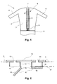
- FIG. 1 shows a device 1 for smoothing shirts, which has a device 6 is equipped to fix the button and buttonhole bar of a shirt 17.
- the Shirt smoothing device 1 has an inflatable bag 2 with a torso section 3 and two adjoining sleeve sections 4 for tensioning the shirt 17.
- the Inflatable bag 2 and the device 6 for fixing the button and buttonhole bar are attached to a base 5, which also serves as a base for the device and in Figure 1 only is partially shown.
- the base 5 has in particular the control for the device and a blower and a heater with which the inflatable bag 2 is inflated with heated air can be.
- the inflatable bag 2 is made of an air-permeable material, through which the heated air can reach a shirt. additionally can be provided that the inflatable bag 2 can also be filled with steam.
- FIG 2 is a horizontal section through the device 6 for fixing the button and the buttonhole bar shown.
- a base plate 12 which is connected to the base 5 is connected, two terminal strips 14 are attached, against which the button strip or the buttonhole of shirt 17 can be clamped.
- the front of the terminal strips 14 are closed with perforated plates 15.
- the terminal strips 14 have openings which correspond to openings in the carrier plate 12 match and form air passages 13.
- the inflatable bag On the outer edges of the carrier plate 12 is the inflatable bag in addition to the terminal strips 14 2 attached with its fuselage section so that air from the inflatable bag 2 through the Passages 13 and the perforated plates 15 up to a clamped on the terminal strips 14 Button bar or buttonhole bar can get.
- Flaps 8 are pivotally attached to the inside of the terminal strips 14, with which the button panel or the buttonhole panel of the shirt 17 against the terminal strips 14 can be pressed.
- the flaps 8 form in the described embodiment the fixing elements and are arranged in two rows 7, which are almost the extend the entire height of the fuselage section 3 of the inflatable bag 2.
- the flaps 8 have an air-permeable clamp body 10, for example made of a porous, foamed Plastic can exist.
- On the side facing the terminal strips 14 the clamping body 10 is covered by a perforated plate 16.
- the perforated plate 16 can Metal or a soft elastic plastic to avoid unevenness Adjust the button or buttonhole bar and in particular buttons sewn onto it to be able to.
- the clamping body 10 is impermeable to air.
- the clamping body 10 itself can be flexible, whereby the perforated plate 16 can be omitted, so that the clamping body 10 directly on the button or Buttonhole bar is pressed.
- the flaps 8 are each assigned spring elements that they from a certain opening angle press into the open position and counter it below this opening angle press the terminal block 14.
- the flaps 8 can individually manually from their open position so far that they snap shut and by the spring be pressed against the terminal block 14.
- a slide 9 is provided, which by means of a Guide bar, not shown, is slidably connected to the base plate 12 and serves as an actuating element for the flaps 8.
- the flaps 8 devices are assigned, which when pushing the Slider 9 from bottom to top closing the flaps beyond the dead center cause.
- the flaps 8 can thus be closed both individually and manually all together by moving the slide 9 from the bottom to the bottom above. It is also provided that when the slide 9 is moved in reverse Direction, that is, from top to bottom, the flaps 8 from their closed Condition brought into the open. Conversely, it can also be provided that the flaps 8 closed when moving the slide 9 from top to bottom and be opened when moving from bottom to top.
- the shirt 17 can be smoothed by heating air from the base 5 the inflatable bag 2 is directed, which then inflates and tightens the shirt 17. there escapes through the permeable material of the inflatable bag 2 to the heated air put on shirt 17 and smooth it. If the shirt 17 is put on when wet, it is dried under tension by the heated air, being a better Smoothing is achieved.
- heated air flows from the inside of the Inflatable bags 2 through the passages 13 in the hollow terminal strips 14 and can through Perforated sheets 15 from the inside to the clamped button or Buttonhole bar. Because of the passages 13 and the perforated plates 15 can also allows better humidification with steam or water or water mist become.
- the solution according to the invention ensures that the shirt 17 to be smoothed by an operator can be fixed quickly and easily, with the possibility of to fix individual areas one after the other, the button and buttonhole placket simply can be aligned straight and without wrinkles.
Landscapes
- Engineering & Computer Science (AREA)
- Textile Engineering (AREA)
- Details Of Garments (AREA)
Description
Die Erfindung bezieht sich auf eine Vorrichtung zum Fixieren der Knopfleiste und der Knopflochleiste eines Hemds zur Verwendung in einer Vorrichtung zum Glätten von Hemden, wobei die Erfindung allgemein bei über die gesamte Höhe an der Brustseite zu öffnenden Hemden unabhängig von der Verschlußart angewendet werden kann.The invention relates to a device for fixing the button panel and Buttonhole bar of a shirt for use in a device for smoothing Shirts, the invention generally being over the full height on the chest side too opening shirts can be used regardless of the type of closure.
Bei Vorrichtungen zum Glätten von Hemden wird das Hemd üblicherweise gespannt, um dessen Gewebe zu glätten. Dazu ist es nötig, das Hemd an verschiedenen Stellen zu fixieren, um es spannen zu können. Insbesondere um das Hemd nach dem Glätten besser abnehmen zu können, kann es vorteilhaft sein, das Hemd im nicht zugeknöpften Zustand zu glätten. In diesem Fall ist jedoch ein Fixieren der Knopfleiste beziehungsweise der Knopflochleiste erforderlich.In shirt smoothing devices, the shirt is usually stretched to to smooth its tissue. For this it is necessary to fix the shirt in different places, to be able to stretch it. Especially around the shirt better after smoothing to be able to take off, it can be advantageous to keep the shirt in the unbuttoned state to smooth out. In this case, however, the button strip or the Buttonhole bar required.
Durch die US 3,165,244 ist eine Vorrichtung zum Glätten von Hemden bekannt, bei der die Knopfleiste und die Knopflochleiste parallel nebeneinander jeweils durch mehrere Klemmbacken gehalten werden. Die Klemmbacken für die Knopfleiste beziehungsweise die Knopflochleiste sind jeweils durch eine Feder vorgespannt und mit einer Leiste miteinander verbunden, so daß sie von einer Bedienperson gemeinsam geöffnet und geschlossen werden können. Vorher müssen jedoch dünne Stangen in die Knopfleiste und die Knopflochleiste eingeführt werden, um diese zu versteifen und eine ausreichende Fixierung über deren gesamte Länge zu ermöglichen. Dies ist zum einen bei den meisten Hemden nicht möglich und zum anderen mit einem hohen zeitlichen Aufwand für die Bedienperson verbunden. Weiterhin muß Knopfleiste und die Knopflochleiste über deren gesamte Länge richtig angeordnet werden, bevor die Klemmbacken in ihre Fixierstellung gebracht werden können.A device for smoothing shirts is known from US Pat. No. 3,165,244 the button panel and the buttonhole panel in parallel next to each other by several Jaws are held. The jaws for the button placket respectively the buttonhole bar is each biased by a spring and together with a bar connected so that they are opened and closed together by one operator can be. Before that, however, thin bars must be inserted into the button panel and the buttonhole placket are inserted to stiffen it and adequate fixation over their entire length. For one, this is the case with most Shirts are not possible and, on the other hand, it takes a lot of time for the operator connected. Furthermore, the button panel and the buttonhole panel must be over their entire length must be correctly arranged before the jaws in their fixing position can be brought.
Der vorliegenden Erfindung liegt die Aufgabe zugrunde, eine Vorrichtung der eingangs genannten Art zu schaffen, bei der das Anlegen und Fixieren der Knopfleiste beziehungsweise der Knopflochleiste von der Bedienperson einfacher und genauer durchgeführt werden kann. The present invention has for its object a device of the beginning to create the type mentioned, in which the application and fixing of the button panel respectively the buttonhole bar carried out more easily and precisely by the operator can be.
Diese Aufgabe wird erfindungsgemäß dadurch gelöst, daß die Fixiervorrichtung mehrere in Reihe entlang der Knopfleiste und/oder Knopflochleiste angeordnete Fixierelemente aufweist, die einzeln betätigt werden können.This object is achieved in that the fixing device several in series along the button panel and / or buttonhole panel has arranged fixing elements that can be operated individually.
Auf diese Weise ist es möglich, beim Auflegen des Hemds die Knopfleiste beziehungsweise die Knopflochleiste zunächst nur in einem Teilbereich in die richtige Position zu bringen und das zugeordnete Fixierelement oder die zugeordneten Fixierelemente vorab in den Fixierzustand zu bringen, um die Knopfleiste beziehungsweise die Knopflochleiste an einer Stelle bereits zu fixieren. Danach kann dieser Vorgang an einer anderen Stelle wiederholt werden, so daß auf diese Weise die Knopfleiste beziehungsweise die Knopflochleiste in mehreren Schritten vorab zumindest punktuell fixiert werden und in die für die Fixierung richtige Position gebracht werden kann. Beispielsweise können Fixierelemente am unteren und am oberen Ende der Knopfleiste beziehungsweise der Knopflochleiste vorgesehen sein, zwischen denen man die Knopfleiste beziehungsweise die Knopflochleiste insbesondere unter leichter Spannung fixieren kann. Die Fixierelemente müssen nicht notwendigerweise die gleiche Größe besitzen, sondern können beispielsweise an den Rändern der Knopf- beziehungsweise Knopflochleiste kleiner und im Mittelbereich größer sein.In this way it is possible to put the button panel on when putting on the shirt the buttonhole bar initially only in the correct position in a partial area bring and the associated fixation element or fixation elements in advance to bring into the fixation state around the button panel or the buttonhole panel already fixed in one place. After that, this process can be done elsewhere can be repeated, so that the button panel or the buttonhole panel in several steps in advance at least selectively and in the for the Fixation correct position can be brought. For example, fixing elements at the bottom and at the top of the button panel and the buttonhole panel be provided between which one has the button panel or the buttonhole panel can fix especially under slight tension. The fixing elements must do not necessarily have the same size, but can, for example smaller at the edges of the button or buttonhole placket and in the middle to be taller.
Anschließend können die übrigen Fixierelemente betätigt werden, um die Knopfleiste beziehungsweise die Knopflochleiste über ihre gesamte Länge zu fixieren.Then the remaining fixing elements can be operated to the button bar or to fix the buttonhole bar over its entire length.
Weiterhin kann wenigstens ein Betätigungselement vorgesehen sein, mit dem eine Gruppe mehrerer Fixierelemente gemeinsam betätigt werden kann.Furthermore, at least one actuating element can be provided with which a group several fixing elements can be operated together.
Mit einem solchen Betätigungselement können mehrere Fixierelemente gemeinsam in ihren Fixierzustand gebracht werden. Dazu kann vorgesehen sein, daß beispielsweise alle Fixierelemente mit einem Betätigungselement gemeinsam betätigt werden können, so daß die Knopfleiste und die Knopflochleiste auf einmal vollständig fixiert werden können. Ebenso ist es denkbar, Bereiche mit mehreren, mit einem Betätigungselement gemeinsam betätigbaren Fixierelementen festzulegen, beispielsweise für Bereiche entlang der Knopf- beziehungsweise Knopflochleiste.With such an actuating element, several fixing elements can be used jointly in their Fixing state are brought. It can be provided that, for example, all Fixing elements can be operated together with an actuating element, so that the button panel and the buttonhole panel can be completely fixed at once. It is also conceivable to share areas with several actuators define actuatable fixing elements, for example for areas along the Button or buttonhole bar.
Dabei kann eine Reihe von Fixierelementen vorgesehen sein, wobei die Knopf- und die Knopflochleiste von den Fixierelementen gemeinsam gehalten werden. Die Knopf- und die Knopflochleiste können dabei nebeneinander oder übereinander liegend fixiert werden. Vorteilhafterweise sind jedoch zwei Reihen von Fixierelementen vorgesehen, mit denen die Knopf- und die Knopflochleiste nebeneinander getrennt angelegt und fixiert werden können.A number of fixing elements can be provided, the button and the Buttonhole bar can be held together by the fixing elements. The button and the buttonhole placket can be fixed side by side or one above the other. However, two rows of fixing elements are advantageously provided with which the button and buttonhole strips are created and fixed next to each other separately can.
Nach dem Glätten des Hemds können umgekehrt die gemeinsam betätigbaren Fixierelemente mit dem wenigstens einen Betätigungselement wieder geöffnet beziehungsweise in ihren Ausgangszustand gebracht werden, um die Knopf- und die Knopflochleiste wieder freizugeben und das Hemd abnehmen zu können.After the shirt has been smoothed, the jointly operable fixing elements can be reversed opened again with the at least one actuating element or be brought back to their original state to the button and buttonhole bar again to be able to release and take off the shirt.
Als Ausführungsform für die Fixiervorrichtung ist beispielsweise eine biegsame Klemmleiste denkbar, bei der einzelne Bereiche unabhängig voneinander gegen eine weitere Klemmleiste gepreßt werden können und so getrennt voneinander betätigbare Fixierelemente bilden. Weiterhin ist es denkbar, die Knopfleiste beziehungsweise die Knopflochleiste mit Unterdruck anzusaugen und so zu fixieren, wobei die Fixierelemente in diesem Fall von getrennt voneinander mit Unterdruck beaufschlagbaren Bereichen gebildet werden.An example of an embodiment for the fixing device is a flexible terminal strip conceivable in which individual areas independently of one another Terminal strip can be pressed and thus separately operable fixing elements form. It is also conceivable for the button panel or the buttonhole panel suck in with vacuum and so fix, the fixing elements in this Case formed from areas which can be subjected to negative pressure separately from one another become.
Vorteilhafterweise erstrecken sich die Fixierelemente im wesentlichen ohne Abstände zueinander über eine Länge, die größer ist als die der Knopfleisten beziehungsweise der Knopflochleisten üblicher Hemden. So kann die Knopfleiste beziehungsweise die Knopflochleiste üblicher Hemden über die ganze Länge fixiert werden, so daß es bei einem Spannen des Hemds nicht zu Verwerfungen des Gewebes kommen kann.The fixing elements advantageously extend essentially without any spacing from one another over a length that is greater than that of the button strips or Buttonhole strips of usual shirts. So the button bar or the buttonhole bar usual shirts can be fixed over the entire length, so that it is one Tensioning the shirt cannot cause warping of the fabric.
In einer vorteilhaften Ausführungsform sind die Fixierelemente in zwei nebeneinander liegenden, parallelen Reihen angeordnet und können mittels eines Betätigungselements alle Fixierelemente gemeinsam betätigt werden. Die Knopfleiste und die Knopflochleiste können auf diese Weise unabhängig voneinander nebeneinander fixiert werden. Zusätzlich kann in diesem Fall ein Spalt zwischen den beiden Fixierelementenreihen vorgesehen werden, durch den hindurch von außen wirkende Klemmittel mit von innen wirkenden Klemmitteln einfach und unter Vermeidung großer Hebelkräfte verbunden werden können.In an advantageous embodiment, the fixing elements are in two adjacent, arranged parallel rows and can all by means of an actuator Fixing elements are operated together. The button panel and the buttonhole panel can can be fixed next to each other in this way independently. additionally In this case, a gap can be provided between the two rows of fixing elements through which the clamping means acting from the outside act from the inside Clamping means can be connected easily and avoiding great leverage.
Die Fixierelemente können als schwenkbaren Klappen ausgebildet werden, die getrennt von einander manuell in eine Fixierstellung gebracht werden können, in der sie von einer Feder gespannt die Knopfleiste und die Knopflochleiste jeweils gegen eine Klemmleiste klemmen können. Ebenso können die Fixierelemente in Form von schwenkbaren Klappen getrennt voneinander manuell aus der Fixierstellung in eine stabile Offenstellung bewegbar sein, in der sie die Knopfleiste beziehungsweise die Knopflochleiste freigeben können. Die Klappen können dazu so ausgebildet sein, daß sie von einer Feder im offenen Zustand gehalten werden und bei einem manuellen Verschwenken über einen Totpunkt hinaus von der Feder gegen eine Klemmleiste gedrückt werden. Damit kann auch die Funktion verwirklicht werden, daß sich die Klappen manuell wieder öffnen lassen und beim Verschwenken über den Totpunkt hinaus von der Feder in die Offenstellung bewegt werden.The fixing elements can be designed as pivotable flaps, which are separated can be brought from each other manually into a fixing position in which they can be Spring tensioned the button panel and the buttonhole panel each against a terminal strip can jam. Likewise, the fixing elements in the form of pivotable flaps can be moved separately from one another manually from the fixing position into a stable open position in which you can release the button panel or buttonhole panel. The flaps can be designed so that they are open by a spring Condition are maintained and when pivoting manually over a dead center be pressed by the spring against a terminal block. So that can Function can be realized that the flaps can be opened manually and when pivoting beyond the dead center moved by the spring in the open position become.
Die Knopfleiste und die Knopflochleiste können auf diese Weise einfach fixiert werden, indem jeweils ein Teil von ihnen an die richtige Stelle gehalten wird und die zugeordneten Klappen umgelegt werden, um die Knopf- und die Knopflochleiste an diesen Stellen vorab zu fixieren. Anschließend können mit einem Betätigungselement alle Fixierelemente in ihrem Fixierzustand gebracht werden, um Knopf- und Knopflochleiste über die gesamte Länge zu fixieren. Dazu können beispielsweise mit dem Betätigungselement alle noch offenen Klappen in die Fixierstellung umgeklappt werden. Dabei kann auch vorgesehen sein, daß mit dem Betätigungselement eine zur Federkraft zusätzliche Kraft auf die Klappen ausgeübt wird, so daß diese fester gegen die Klemmleiste gedrückt werden. Zusätzlich kann bei diesem Vorgang auch eine Verriegelung der Klappen in ihre Fixierstellung erfolgen.The button panel and the buttonhole panel can be easily fixed in this way, by holding a part of them in the right place and the assigned ones Flaps can be flipped over to the button and buttonhole placket at these locations in advance to fix. Subsequently, all fixing elements can be in their with an actuating element Fixing condition brought to the button and buttonhole bar over the entire Fix length. For this purpose, for example, everyone can still use the actuating element open flaps can be folded down into the fixing position. It can also be provided be that with the actuator an additional force to the spring force on the flaps is exercised so that these are pressed more firmly against the terminal block. additionally can also lock the flaps in their fixing position during this process respectively.
In vielen Fällen wird das Hemd im feuchten Zustand gespannt und währenddessen getrocknet, um ein besseres Glättungsergebnis zu erzielen. Dabei kann das Trocknen von dickeren Stellen wie zum Beispiel die Knopf- und die Knopflochleiste Probleme bereiten.In many cases, the shirt is stretched when wet and then dried, to get a better smoothing result. The drying of thicker areas such as the button and buttonhole bar cause problems.
Für diese Fälle kann vorgesehen sein, daß die Klemmleisten den Durchtritt von Luft zu einer festgeklemmten Knopfleiste beziehungsweise Knopflochleiste ermöglichen und daß die Klappen einen luftdurchlässigen Klemmkörper aufweisen, der auf den nicht der Klemmleiste zugewandten Seiten luftundurchlässig ist. In der Regel wird die Klemmleiste von der Knopf- beziehungsweise Knopflochleiste nicht vollständig bedeckt, so daß in diesem Fall etwas Trocknungsluft zu den Klappen strömen kann. Diese an der Knopf- beziehungsweise Knopflochleiste vorbeigeströmte Trocknungsluft kann in den luftdurchlässigen Klemmkörper eindringen, diesen durchströmen und von dort an die Knopf- beziehungsweise Knopflochleiste gelangen und so diese von außen trocknen. Da die nicht der Klemmleiste zugewandten Seiten luftundurchlässig sind, wird die Trocknungsluft innerhalb des luftdurchlässigen Klemmkörpers verstärkt zur Knopf- beziehungsweise Knopflochleiste hin geleitet. In these cases, it can be provided that the terminal strips prevent the passage of air allow a clamped button bar or buttonhole bar and that the flaps have an air-permeable clamp body that is not on the Terminal block facing sides is airtight. Usually the terminal block not completely covered by the button or buttonhole bar, so that in this If some drying air can flow to the flaps. These on the button respectively Buttonhole placket drying air flowing past can be in the air-permeable Penetrating body penetrate, flow through it and from there to the button or Buttonhole bar and dry it from the outside. Since they are not Terminal block facing sides are airtight, the drying air inside of the air-permeable clamp body reinforced to the button or buttonhole bar headed there.
Weiterhin kann vorgesehen sein, daß die Klemmleisten einen Luftkanal aufweisen, mit dem nicht durch die Klemmleisten hindurchgeströmte Luft zur Rückgewinnung von Wärme abgeleitet werden kann. Zum einen kann so Wärmeenergie zum Teil rückgewonnen und zum anderen kann innen an der Knopf- beziehungsweise Knopflochleiste eine zusätzliche Luftströmung erzielt werden.Furthermore, it can be provided that the terminal strips have an air duct with the air that has not flowed through the terminal strips to recover heat can be derived. On the one hand, heat energy can be partially recovered and on the other hand, an additional one on the inside of the button or buttonhole bar Air flow can be achieved.
Falls zum Spannen des Hemds ein aufblasbarer Blähsack verwendet wird, können Einrichtungen zum Befestigen des Blähsacks an den jeweils äußeren Rändern der Klemmleisten vorgesehen sein. Auf diese Weise wird der Blähsack, der im nicht aufgeblasenen Zustand zusammenfallen würde, an der Vorrichtung zum Fixieren der Knopf- beziehungsweise Knopflochleiste gehalten, so daß er einfacher innerhalb des Hemdes in die richtige Stellung gebracht werden kann. Dies gilt insbesondere für Ärmelansätze, die in die Ärmel eines aufgelegten Hemdes hineingesteckt werden müssen.If an inflatable inflatable bag is used to stretch the shirt, facilities can be used for attaching the inflatable bag to the outer edges of the terminal strips be provided. In this way, the inflatable bag that is not inflated State would coincide on the device for fixing the button respectively Buttonhole placket held so that it is easier inside the shirt in the correct position can be brought. This is especially true for sleeve approaches that in the sleeves of a shirt put on must be inserted.
Das wenigstens eine Betätigungselement kann so ausgestaltet sein, daß es an den Fixierelementen entlang verschiebbar ist und bei der Verschiebung in eine Richtung die Fixierelemente in ihren Fixierzustand und bei der Verschiebung in die andere Richtung wieder in ihren Ruhezustand versetzt. Das Betätigungselement wird dabei wie bei einem Reißverschluß an den Fixierelementen entlang bewegt und schließt beziehungsweise öffnet die Fixierelemente nacheinander. Da die Fixierelemente einzeln betätigt werden, ist die von der Bedienperson aufzuwendende Kraft geringer beziehungsweise kann von der Bedienperson zum Betätigen eines einzelnen Fixierelements mehr Kraft aufgewendet werden.The at least one actuating element can be designed so that it is on the fixing elements is displaceable along and when moving in one direction the fixing elements in their fixed state and when moving in the other direction again put into their idle state. The actuator is like a Zipper moves along the fixing elements and closes or opens the fixing elements one after the other. Since the fixing elements are actuated individually the force to be used by the operator is lower or can be from the Operator used more force to operate a single fixing element become.
Weiterhin ist es auch möglich, daß das wenigstens eine Betätigungselement für jede Reihe von Fixierelementen eine Stange aufweist, mit der durch Dreh- oder Schubbewegung die zugeordnete Reihe von Fixierelementen betätigt werden können, wobei die Fixierelemente bei Betätigung der Stange gleichzeitig oder auch nacheinander betätigt werden können.Furthermore, it is also possible for the at least one actuating element for each row of fixing elements has a rod with which by rotating or pushing movement the associated row of fixing elements can be actuated, the fixing elements when the rod is actuated simultaneously or in succession can.
Weitere Einzelheiten, Merkmale und Vorteile der Erfindung ergeben sich aus der folgenden Beschreibung einer Vorrichtung zum Glätten von Hemden mit einem Ausführungsbeispiel für eine erfindungsgemäße Vorrichtung zum Fixieren der Knopf- und der Knopflochleiste eines Hemds unter Bezugnahme auf die Zeichnungen. Darin zeigen:
- Fig. 1
- eine Vorderansicht einer Vorrichtung zum Glätten von Hemden mit einer erfindungsgemäßen Vorrichtung zum Fixieren der Knopfbeziehungsweise Knopflochleiste und
- Fig. 2
- eine Schnittansicht von oben durch die Vorrichtung zum Fixieren der Knopf- beziehungsweise Knopflochleiste.
- Fig. 1
- a front view of a device for smoothing shirts with an inventive device for fixing the button or buttonhole bar and
- Fig. 2
- a sectional view from above through the device for fixing the button or buttonhole bar.
Figur 1 zeigt eine Vorrichtung 1 zum Glätten von Hemden, die mit einer Vorrichtung 6
zum Fixieren der Knopf- und der Knopflochleiste eines Hemds 17 ausgerüstet ist. Die
Hemdenglättvorrichtung 1 weist einen Blähsack 2 mit einem Rumpfabschnitt 3 sowie zwei
sich daran anschließenden Ärmelabschnitten 4 zum Spannen des Hemds 17 auf. Der
Blähsack 2 sowie die Vorrichtung 6 zum Fixieren der Knopf- und der Knopflochleiste sind
auf einem Sockel 5 befestigt, der auch als Standfuß für das Gerät dient und in Figur 1 nur
teilweise dargestellt ist. Der Sockel 5 weist insbesondere die Steuerung für das Gerät sowie
ein Gebläse und eine Heizung auf, mit denen der Blähsack 2 mit erwärmter Luft aufgeblasen
werden kann. Der Blähsack 2 besteht aus einem luftdurchlässigen Material,
durch das die erwärmte Luft hindurch zu einem aufgelegten Hemd gelangen kann. Zusätzlich
kann vorgesehen sein, daß der Blähsack 2 auch mit Dampf gefüllt werden kann.FIG. 1 shows a
In Figur 2 ist ein waagerechter Schnitt durch die Vorrichtung 6 zum Fixieren der Knopfund
der Knopflochleiste dargestellt. Vorne an einer Grundplatte 12, die mit dem Sockel 5
verbunden ist, sind dabei zwei Klemmleisten 14 befestigt, gegen die die Knopfleiste beziehungsweise
die Knopflochleiste des Hemds 17 festgeklemmt werden kann. Auf der
Vorderseite sind die Klemmleisten 14 mit Lochblechen 15 abgeschlossen. Auf der Rückseite
weisen die Klemmleisten 14 Öffnungen auf, die mit Öffnungen in der Trägerplatte 12
übereinstimmen und Luftdurchtritte 13 bilden.In Figure 2 is a horizontal section through the
An den äußeren Rändern der Trägerplatte 12 ist neben den Klemmleisten 14 der Blähsack
2 mit seinem Rumpfabschnitt befestigt, so daß Luft aus dem Blähsack 2 durch die
Durchtritte 13 und die Lochbleche 15 bis zu einer auf den Klemmleisten 14 festgeklemmten
Knopfleiste beziehungsweise Knopflochleiste gelangen kann.On the outer edges of the
Innen an den Klemmleisten 14 sind jeweils Klappen 8 schwenkbar befestigt, mit denen
die Knopfleiste beziehungsweise die Knopflochleiste des Hemds 17 gegen die Klemmleisten
14 gepreßt werden können. Die Klappen 8 bilden im beschriebenen Ausführungsbeispiel
die Fixierelemente und sind in zwei Reihen 7 angeordnet, die sich über nahezu die
gesamte Höhe des Rumpfabschnitts 3 des Blähsacks 2 erstrecken. Die Klappen 8 weisen
einen luftdurchlässigen Klemmkörper 10 auf, der beispielsweise aus einem porösen, aufgeschäumten
Kunststoff bestehen kann. Auf der den Klemmleisten 14 zugewandten Seite
wird der Klemmkörper 10 durch eine Lochplatte 16 bedeckt. Die Lochplatte 16 kann aus
Metall oder aus einem weichelastischen Kunststoff bestehen, um sich Unebenheiten auf
der Knopf- oder der Knopflochleiste und insbesondere darauf festgenähten Knöpfen anpassen
zu können. Auf den übrigen Seiten ist der Klemmkörper 10 luftundurchlässig. In
einer anderen Ausgestaltung kann der Klemmkörper 10 selbst weichelastisch sein, wobei
die Lochplatte 16 entfallen kann, so daß der Klemmkörper 10 direkt auf die Knopf- beziehungsweise
Knopflochleiste gedrückt wird.
Den Klappen 8 sind jeweils Federelemente zugeordnet, die sie ab einem gewissen Öffnungswinkel
in die offene Stellung drücken und sie unterhalb dieses Öffnungswinkels gegen
die Klemmleiste 14 drücken. Die Klappen 8 können dabei einzeln manuell aus ihrer
offenen Stellung soweit geschlossen werden, daß sie zuschnappen und von der Feder
gegen die Klemmleiste 14 gedrückt werden.The
Zwischen den beiden Klemmleisten 14 ist ein Schieber 9 vorgesehen, der mittels einer
nicht dargestellten Führungsleiste verschiebbar mit der Grundplatte 12 verbunden ist und
als Betätigungselement für die Klappen 8 dient.Between the two
Dazu sind den Klappen 8 Einrichtungen zugeordnet, die bei einem Vorbeischieben des
Schiebers 9 von unten nach oben ein Schließen der Klappen über den Totpunkt hinaus
bewirken. Die Klappen 8 können somit sowohl einzeln manuell geschlossen werden, als
auch alle gemeinsam durch ein Verschieben des Schiebers 9 von ganz unten nach ganz
oben. Weiterhin ist vorgesehen, daß bei einem Verschieben des Schiebers 9 in umgekehrter
Richtung, daß heißt von oben nach unten, die Klappen 8 aus ihren geschlossenen
Zustand in den offenen gebracht werden. Dabei kann auch umgekehrt vorgesehen sein,
daß die Klappen 8 bei einem Verschieben des Schiebers 9 von oben nach unten geschlossen
und bei einem Verschieben von unten nach oben geöffnet werden.For this purpose, the
Zum Glätten des Hemds 17 wird dieses über den Blähsack 2 gelegt, wobei es nur mit der
Knopf- und der Knopflochleiste vorne fixiert werden muß. Dazu werden zunächst alle
Klappen 8 durch ein Verschieben des Schiebers 9 von ganz oben nach ganz unten in die
offene Stellung gebracht. Danach kann die Knopf- beziehungsweise die Knopflochleiste
zunächst an einer Stelle auf die zugeordnete Klemmleiste 14 gelegt und durch Umlegen
der zugeordneten Klappe 8 beziehungsweise Klappen 8 vorab an dieser Stelle fixiert werden.
Dieser Vorgang kann an verschiedenen Stellen wiederholt werden, bis die Knopfbeziehungsweise
Knopflochleiste über deren gesamte Länge zumindest richtig angeordnet
ist, wobei sie nicht notwendigerweise vollständig fixiert sein muß. Zum Schluß wird
der Schieber 9 von unten bis nach ganz oben verschoben, so daß die noch verbleibenden
offenen Klappen 8 geschlossen werden und die Knopf- und die Knopflochleiste über deren
gesamte Länge fixiert sind.To smooth the
Danach kann das Hemd 17 geglättet werden, indem vom Sockel 5 aus erwärmte Luft in
den Blähsack 2 geleitet wird, der sich daraufhin aufbläht und das Hemd 17 spannt. Dabei
entweicht durch das durchlässige Material des Blähsacks 2 die erwärmte Luft zu dem
aufgelegten Hemd 17 und glättet dieses. Wird das Hemd 17 im feuchten Zustand aufgelegt,
wird es durch die erwärmte Luft unter Spannung getrocknet, wobei eine bessere
Glättung erreicht wird. Während des Glättens strömt erwärmte Luft vom Inneren des
Blähsacks 2 durch die Durchtritte 13 in die hohlen Klemmleisten 14 und kann durch die
Lochbleche 15 hindurch von innen an die festgeklemmte Knopf- beziehungsweise
Knopflochleiste gelangen. Aufgrund der Durchtritte 13 und der Lochbleche 15 kann auch
eine bessere Befeuchtung mit Dampf beziehungsweise Wasser oder Wassernebel ermöglicht
werden.Thereafter, the
Falls wie in Figur 2 dargestellt eine festgeklemmte Knopf- beziehungsweise Knopflochleiste
die zugeordnete Klemmleiste 14 nicht vollständig bedeckt, kann die Luft zu dem
Klemmkörper 10 gelangen, sich in diesem verteilen und zusätzlich von außen an die festgeklemmte
Knopf- beziehungsweise Knopflochleiste gelangen. Auf diese Weise wird ein
besserer Kontakt der Knopf- beziehungsweise Knopflochleiste mit der Luft erreicht, der
auch eine Trocknung der in der Regel mehrlagigen Knopf- beziehungsweise Knopflochleiste
erleichtert. Während des Glättungsvorgangs kann aus den Klemmleisten 14 an
deren unteren Ende Luft in den Sockel 5 abgeleitet werden, um Wärme zurückzugewinnen.If, as shown in Figure 2, a clamped button or buttonhole bar
the associated
Wenn der Glättungsvorgang beendet ist, können alle Klappen 8 durch ein Verschieben
des Schiebers 9 von oben nach unten geöffnet werden, so daß das Hemd 17 abgenommen
werden kann.When the smoothing process is finished, all
Durch die erfindungsgemäße Lösung wird erreicht, daß das zu glättende Hemd 17 von
einer Bedienperson schnell und einfach fixiert werden kann, wobei durch die Möglichkeit,
einzelne Bereiche nacheinander zu fixieren, die Knopf- und die Knopflochleiste einfach
gerade und ohne Falten ausgerichtet werden können.The solution according to the invention ensures that the
Claims (10)
- Device (6) for fixing the button strip and the buttonhole strip of a shirt (17) characterised in that the fixing device (6) comprises several fixing elements (8) which are arranged in a row along the button strip and/or the buttonhole strip and which can be individually actuated.
- Device according to claim 1, characterised in that the fixing device (6) comprises at least one actuating element (9) which can be actuated in common with a group of several fixing elements (8).
- Device according to claim 1 or 2, characterised in that the fixing elements (8) extend substantially without spacings relative to one another over a length greater than that of the button strips or the buttonhole strips of conventional shirts.
- Device according to one of claims 1 to 3, characterised in that the fixing elements (8) are arranged in two mutually adjacent parallel rows (7) and that all fixing elements (8) can be actuated in common with an actuating element (9).
- Device according to one of claims 1 to 4, characterised in that the fixing elements (8) are constructed as pivotable flaps, which can be manually brought separately from one another into a fixing setting in which, clamped by a spring, they can clamp each of the button strip and the buttonhole strip against a respective clamping strip (14) and/or can be manually moved separately from one another out of the fixing setting into a stable rest setting in which the fixing elements (8) free the button strip and the buttonhole strip.
- Device according to claim 5 , characterised in that the clamping strips (14) enable the passage of air to a button strip or buttonhole strip clamped in place and that the fixing elements (8) have an air-permeable damping body (10) which is air-impermeable on the side not facing the associated clamping strip (14).
- Device according to claim 5 or 6, characterised in that the clamping strips (14) have an air channel by which air not flowing through the clamping strips (14) can be conducted away for recovery of heat.
- Device according to one of claims 5 to 7, characterised in that it comprises devices for fastening an inflatable bag (2) for clamping the shirt (17) at the respective outer edges of the clamping strips (14).
- Device according to claim 4, characterised in that the at least one actuating element (9) is displaceable along the fixing elements (8) and on displacement in one direction shifts the fixing elements (8) into their fixing state and on displacement in the other direction shifts them back into their rest state.
- Device according to one of claims 4 and 9, characterised in that the at least one actuating element has for each row (7) of fixing elements (8) a rod by which the associated row (7) of fixing elements (8) can be actuated by a rotary or pushing movement.
Applications Claiming Priority (2)
| Application Number | Priority Date | Filing Date | Title |
|---|---|---|---|
| DE19932452 | 1999-07-12 | ||
| DE19932452A DE19932452A1 (en) | 1999-07-12 | 1999-07-12 | Device for fixing the button placket of a shirt |
Publications (2)
| Publication Number | Publication Date |
|---|---|
| EP1069229A1 EP1069229A1 (en) | 2001-01-17 |
| EP1069229B1 true EP1069229B1 (en) | 2003-10-01 |
Family
ID=7914444
Family Applications (1)
| Application Number | Title | Priority Date | Filing Date |
|---|---|---|---|
| EP00114544A Expired - Lifetime EP1069229B1 (en) | 1999-07-12 | 2000-07-06 | Device to hold the button strip of a shirt |
Country Status (3)
| Country | Link |
|---|---|
| EP (1) | EP1069229B1 (en) |
| DE (2) | DE19932452A1 (en) |
| ES (1) | ES2208190T3 (en) |
Families Citing this family (4)
| Publication number | Priority date | Publication date | Assignee | Title |
|---|---|---|---|---|
| DE10156859A1 (en) | 2001-11-20 | 2003-05-28 | Bsh Bosch Siemens Hausgeraete | Inflatable body to support a shirt and the like, for ironing, has a tensioner support for the row of buttons to hold the garment edges in place, which can be displaced or removed for a closed garment |
| DE10339698A1 (en) * | 2003-08-28 | 2005-03-24 | BSH Bosch und Siemens Hausgeräte GmbH | Device for smoothing article of clothing has stretching unit having stretching body with clamping body made from foam and stretching body having friction layer made from plastics |
| DE10339734A1 (en) * | 2003-08-28 | 2005-03-24 | BSH Bosch und Siemens Hausgeräte GmbH | Inflatable body for ironing garments, and especially shirts, has tensioner for button and buttonhole strips as two clamping bodies with flap connection between them |
| DE10339736A1 (en) * | 2003-08-28 | 2005-03-24 | BSH Bosch und Siemens Hausgeräte GmbH | Inflatable body for ironing garments has clamps to fix points of garment, and remove creases, with swing clamp body pressed in place by lever under spring tension |
Family Cites Families (14)
| Publication number | Priority date | Publication date | Assignee | Title |
|---|---|---|---|---|
| US2361045A (en) * | 1941-08-07 | 1944-10-24 | Us Hoffman Machinery Corp | Garment processing apparatus |
| US2353741A (en) * | 1943-02-20 | 1944-07-18 | American Laundry Mach Co | Garment drier |
| US2417838A (en) * | 1945-02-12 | 1947-03-25 | August F Paris | Garment finishing apparatus |
| US2740566A (en) * | 1951-04-02 | 1956-04-03 | Bill Glover Inc | Shirt finishing machine |
| US3151860A (en) * | 1959-12-31 | 1964-10-06 | Martin R Dosal | Garment holder |
| US3066839A (en) * | 1960-08-24 | 1962-12-04 | Martin R Dosal | Apparatus for pressing shirts |
| US3165244A (en) * | 1962-05-18 | 1965-01-12 | Dosal Martin Roberto | Inflatable apparatus for pressing shirts |
| US3194456A (en) * | 1964-01-22 | 1965-07-13 | Ametek Inc | Shirt-clamping mechanism |
| US3568900A (en) * | 1969-10-27 | 1971-03-09 | August F Paris | Shirt pressing machine |
| US3613969A (en) * | 1970-05-05 | 1971-10-19 | Harry D Forse | Shirt press |
| FR2337779A1 (en) * | 1976-01-09 | 1977-08-05 | Rebiscoul Gerard | Dummy for finishing or ironing garment with centre front opening - grips facing edges without displacement of garment |
| GB2225592A (en) * | 1988-11-23 | 1990-06-06 | Everett Dev Ltd | Garment pressing apparatus |
| IT233390Y1 (en) * | 1994-04-29 | 2000-01-28 | Dalf S N C Di Pessina Enzo & C | PERFECTED MACHINE, PARTICULARLY DESIGNED FOR THE IRONING OF CLOTHING ITEMS SUCH AS SHIRTS OR SIMILAR |
| DE19754026A1 (en) * | 1997-12-05 | 1999-06-10 | Bosch Siemens Hausgeraete | Device for ironing shirts |
-
1999
- 1999-07-12 DE DE19932452A patent/DE19932452A1/en not_active Withdrawn
-
2000
- 2000-07-06 EP EP00114544A patent/EP1069229B1/en not_active Expired - Lifetime
- 2000-07-06 DE DE50003882T patent/DE50003882D1/en not_active Expired - Lifetime
- 2000-07-06 ES ES00114544T patent/ES2208190T3/en not_active Expired - Lifetime
Also Published As
| Publication number | Publication date |
|---|---|
| ES2208190T3 (en) | 2004-06-16 |
| DE19932452A1 (en) | 2001-01-18 |
| DE50003882D1 (en) | 2003-11-06 |
| EP1069229A1 (en) | 2001-01-17 |
Similar Documents
| Publication | Publication Date | Title |
|---|---|---|
| EP1349981B1 (en) | Device for smoothing shirts | |
| EP1069229B1 (en) | Device to hold the button strip of a shirt | |
| DE10063672A1 (en) | Device for smoothing shirts with a divided inflatable body | |
| EP0921227B1 (en) | Device for smoothing of shirt collar | |
| EP1349979A1 (en) | Device for smoothing out shirts | |
| EP1349980B1 (en) | Form finisher with a reinforcement on the end of the sleeve | |
| EP1069231B1 (en) | Device for smoothing shirts | |
| DE102004025914A1 (en) | Clamping device for seam ends and device for drying and / or smoothing a garment | |
| EP1448833A2 (en) | Device for pressing shirt-like garments | |
| DE2913537A1 (en) | DEVICE FOR THERMAL TREATMENT OF TEXTILE ROLLS | |
| EP1510614B1 (en) | Device for pressing garments | |
| EP0662044A1 (en) | DEVICE FOR PRODUCING A PROTECTIVE COVER FOR LOSET SEATS. | |
| WO2005028739A1 (en) | Device for pressing items of clothing, comprising a flexible inflatable body and a tensioning device | |
| EP1069230B1 (en) | Device for smoothing shirts with collars | |
| EP1448834A1 (en) | Inflatable body for pressing shirt-like garments and device for pressing garments with said inflatable body | |
| EP1660713B1 (en) | Device for ironing a piece of garment | |
| EP1528142A2 (en) | Fixing device for fixing a garment cuff to a device for dewrinkling the garment and corresponding fixing mehtod | |
| EP0881317B1 (en) | Finisher | |
| EP1339908A1 (en) | Device for smoothing shirts | |
| DE202024102063U1 (en) | Clothes hangers | |
| DE1960655C (en) | Steam and blow doll | |
| DE202004008892U1 (en) | Press for garments e.g. shirts, blouses or jackets features clamp with support part with contact surface installed through inside of sleeve end and enhances pressing and ironing of cuffs | |
| DE202004008896U1 (en) | Press for outer garments e.g. shirts, blouses, jackets features mobile pressing element for fixing part of body section of goods to be pressed, and frame featuring collar clamp | |
| DE10339716A1 (en) | Device for straightening a garment | |
| DE10339781A1 (en) | Inflatable body for ironing garments, with collars, has clamp for collar to hold it in place without creases, and air openings to indicate that collar is in correct position |
Legal Events
| Date | Code | Title | Description |
|---|---|---|---|
| PUAI | Public reference made under article 153(3) epc to a published international application that has entered the european phase |
Free format text: ORIGINAL CODE: 0009012 |
|
| AK | Designated contracting states |
Kind code of ref document: A1 Designated state(s): DE ES FR GB IT SE |
|
| AX | Request for extension of the european patent |
Free format text: AL;LT;LV;MK;RO;SI |
|
| RIN1 | Information on inventor provided before grant (corrected) |
Inventor name: WETZL, GERHARD Inventor name: DAMRATH, JOACHIM Inventor name: NAUTA, WILHELM Inventor name: SPIELMANNLEITNER, MARKUS |
|
| 17P | Request for examination filed |
Effective date: 20010214 |
|
| AKX | Designation fees paid |
Free format text: DE ES FR GB IT SE |
|
| 17Q | First examination report despatched |
Effective date: 20020910 |
|
| GRAH | Despatch of communication of intention to grant a patent |
Free format text: ORIGINAL CODE: EPIDOS IGRA |
|
| GRAS | Grant fee paid |
Free format text: ORIGINAL CODE: EPIDOSNIGR3 |
|
| GRAA | (expected) grant |
Free format text: ORIGINAL CODE: 0009210 |
|
| AK | Designated contracting states |
Kind code of ref document: B1 Designated state(s): DE ES FR GB IT SE |
|
| REG | Reference to a national code |
Ref country code: GB Ref legal event code: FG4D Free format text: NOT ENGLISH |
|
| REF | Corresponds to: |
Ref document number: 50003882 Country of ref document: DE Date of ref document: 20031106 Kind code of ref document: P |
|
| RAP2 | Party data changed (patent owner data changed or rights of a patent transferred) |
Owner name: BSH BOSCH UND SIEMENS HAUSGERAETE GMBH |
|
| REG | Reference to a national code |
Ref country code: SE Ref legal event code: TRGR |
|
| GBT | Gb: translation of ep patent filed (gb section 77(6)(a)/1977) |
Effective date: 20040122 |
|
| ET | Fr: translation filed | ||
| REG | Reference to a national code |
Ref country code: ES Ref legal event code: FG2A Ref document number: 2208190 Country of ref document: ES Kind code of ref document: T3 |
|
| PLBE | No opposition filed within time limit |
Free format text: ORIGINAL CODE: 0009261 |
|
| STAA | Information on the status of an ep patent application or granted ep patent |
Free format text: STATUS: NO OPPOSITION FILED WITHIN TIME LIMIT |
|
| 26N | No opposition filed |
Effective date: 20040702 |
|
| PGFP | Annual fee paid to national office [announced via postgrant information from national office to epo] |
Ref country code: SE Payment date: 20120723 Year of fee payment: 13 Ref country code: GB Payment date: 20120723 Year of fee payment: 13 |
|
| PGFP | Annual fee paid to national office [announced via postgrant information from national office to epo] |
Ref country code: FR Payment date: 20120803 Year of fee payment: 13 Ref country code: IT Payment date: 20120725 Year of fee payment: 13 Ref country code: DE Payment date: 20120731 Year of fee payment: 13 Ref country code: ES Payment date: 20120723 Year of fee payment: 13 |
|
| REG | Reference to a national code |
Ref country code: SE Ref legal event code: EUG |
|
| GBPC | Gb: european patent ceased through non-payment of renewal fee |
Effective date: 20130706 |
|
| REG | Reference to a national code |
Ref country code: FR Ref legal event code: ST Effective date: 20140331 |
|
| PG25 | Lapsed in a contracting state [announced via postgrant information from national office to epo] |
Ref country code: GB Free format text: LAPSE BECAUSE OF NON-PAYMENT OF DUE FEES Effective date: 20130706 Ref country code: DE Free format text: LAPSE BECAUSE OF NON-PAYMENT OF DUE FEES Effective date: 20140201 Ref country code: SE Free format text: LAPSE BECAUSE OF NON-PAYMENT OF DUE FEES Effective date: 20130707 |
|
| REG | Reference to a national code |
Ref country code: DE Ref legal event code: R119 Ref document number: 50003882 Country of ref document: DE Effective date: 20140201 |
|
| PG25 | Lapsed in a contracting state [announced via postgrant information from national office to epo] |
Ref country code: FR Free format text: LAPSE BECAUSE OF NON-PAYMENT OF DUE FEES Effective date: 20130731 Ref country code: IT Free format text: LAPSE BECAUSE OF NON-PAYMENT OF DUE FEES Effective date: 20130706 |
|
| REG | Reference to a national code |
Ref country code: ES Ref legal event code: FD2A Effective date: 20141010 |
|
| PG25 | Lapsed in a contracting state [announced via postgrant information from national office to epo] |
Ref country code: ES Free format text: LAPSE BECAUSE OF NON-PAYMENT OF DUE FEES Effective date: 20130707 |