EP1069229B1 - Dispositif pour maintenir la partie boutonnée d'une chemise - Google Patents
Dispositif pour maintenir la partie boutonnée d'une chemise Download PDFInfo
- Publication number
- EP1069229B1 EP1069229B1 EP00114544A EP00114544A EP1069229B1 EP 1069229 B1 EP1069229 B1 EP 1069229B1 EP 00114544 A EP00114544 A EP 00114544A EP 00114544 A EP00114544 A EP 00114544A EP 1069229 B1 EP1069229 B1 EP 1069229B1
- Authority
- EP
- European Patent Office
- Prior art keywords
- fixing elements
- button
- buttonhole
- fixing
- strip
- Prior art date
- Legal status (The legal status is an assumption and is not a legal conclusion. Google has not performed a legal analysis and makes no representation as to the accuracy of the status listed.)
- Expired - Lifetime
Links
Images
Classifications
-
- D—TEXTILES; PAPER
- D06—TREATMENT OF TEXTILES OR THE LIKE; LAUNDERING; FLEXIBLE MATERIALS NOT OTHERWISE PROVIDED FOR
- D06F—LAUNDERING, DRYING, IRONING, PRESSING OR FOLDING TEXTILE ARTICLES
- D06F71/00—Apparatus for hot-pressing clothes, linen or other textile articles, i.e. wherein there is substantially no relative movement between pressing element and article while pressure is being applied to the article; Similar machines for cold-pressing clothes, linen or other textile articles
- D06F71/32—Details
- D06F71/40—Holders or stretchers for the article to be pressed
-
- D—TEXTILES; PAPER
- D06—TREATMENT OF TEXTILES OR THE LIKE; LAUNDERING; FLEXIBLE MATERIALS NOT OTHERWISE PROVIDED FOR
- D06F—LAUNDERING, DRYING, IRONING, PRESSING OR FOLDING TEXTILE ARTICLES
- D06F71/00—Apparatus for hot-pressing clothes, linen or other textile articles, i.e. wherein there is substantially no relative movement between pressing element and article while pressure is being applied to the article; Similar machines for cold-pressing clothes, linen or other textile articles
- D06F71/18—Apparatus for hot-pressing clothes, linen or other textile articles, i.e. wherein there is substantially no relative movement between pressing element and article while pressure is being applied to the article; Similar machines for cold-pressing clothes, linen or other textile articles specially adapted for pressing particular garments or parts thereof
- D06F71/20—Apparatus for hot-pressing clothes, linen or other textile articles, i.e. wherein there is substantially no relative movement between pressing element and article while pressure is being applied to the article; Similar machines for cold-pressing clothes, linen or other textile articles specially adapted for pressing particular garments or parts thereof for pressing shirts
-
- D—TEXTILES; PAPER
- D06—TREATMENT OF TEXTILES OR THE LIKE; LAUNDERING; FLEXIBLE MATERIALS NOT OTHERWISE PROVIDED FOR
- D06F—LAUNDERING, DRYING, IRONING, PRESSING OR FOLDING TEXTILE ARTICLES
- D06F73/00—Apparatus for smoothing or removing creases from garments or other textile articles by formers, cores, stretchers, or internal frames, with the application of heat or steam
Definitions
- the invention relates to a device for fixing the button panel and Buttonhole bar of a shirt for use in a device for smoothing Shirts, the invention generally being over the full height on the chest side too opening shirts can be used regardless of the type of closure.
- the shirt is usually stretched to to smooth its tissue. For this it is necessary to fix the shirt in different places, to be able to stretch it. Especially around the shirt better after smoothing to be able to take off, it can be advantageous to keep the shirt in the unbuttoned state to smooth out. In this case, however, the button strip or the Buttonhole bar required.
- a device for smoothing shirts is known from US Pat. No. 3,165,244 the button panel and the buttonhole panel in parallel next to each other by several Jaws are held.
- the jaws for the button placket respectively the buttonhole bar is each biased by a spring and together with a bar connected so that they are opened and closed together by one operator can be.
- thin bars must be inserted into the button panel and the buttonhole placket are inserted to stiffen it and adequate fixation over their entire length. For one, this is the case with most Shirts are not possible and, on the other hand, it takes a lot of time for the operator connected.
- the button panel and the buttonhole panel must be over their entire length must be correctly arranged before the jaws in their fixing position can be brought.
- the present invention has for its object a device of the beginning to create the type mentioned, in which the application and fixing of the button panel respectively the buttonhole bar carried out more easily and precisely by the operator can be.
- the fixing device several in series along the button panel and / or buttonhole panel has arranged fixing elements that can be operated individually.
- the remaining fixing elements can be operated to the button bar or to fix the buttonhole bar over its entire length.
- At least one actuating element can be provided with which a group several fixing elements can be operated together.
- actuating element With such an actuating element, several fixing elements can be used jointly in their Fixing state are brought. It can be provided that, for example, all Fixing elements can be operated together with an actuating element, so that the button panel and the buttonhole panel can be completely fixed at once. It is also conceivable to share areas with several actuators define actuatable fixing elements, for example for areas along the Button or buttonhole bar.
- a number of fixing elements can be provided, the button and the Buttonhole bar can be held together by the fixing elements.
- the button and the buttonhole placket can be fixed side by side or one above the other.
- two rows of fixing elements are advantageously provided with which the button and buttonhole strips are created and fixed next to each other separately can.
- the jointly operable fixing elements can be reversed opened again with the at least one actuating element or be brought back to their original state to the button and buttonhole bar again to be able to release and take off the shirt.
- An example of an embodiment for the fixing device is a flexible terminal strip conceivable in which individual areas independently of one another Terminal strip can be pressed and thus separately operable fixing elements form. It is also conceivable for the button panel or the buttonhole panel suck in with vacuum and so fix, the fixing elements in this Case formed from areas which can be subjected to negative pressure separately from one another become.
- the fixing elements advantageously extend essentially without any spacing from one another over a length that is greater than that of the button strips or Buttonhole strips of usual shirts. So the button bar or the buttonhole bar usual shirts can be fixed over the entire length, so that it is one Tensioning the shirt cannot cause warping of the fabric.
- the fixing elements are in two adjacent, arranged parallel rows and can all by means of an actuator Fixing elements are operated together.
- the button panel and the buttonhole panel can can be fixed next to each other in this way independently. additionally
- a gap can be provided between the two rows of fixing elements through which the clamping means acting from the outside act from the inside Clamping means can be connected easily and avoiding great leverage.
- the fixing elements can be designed as pivotable flaps, which are separated can be brought from each other manually into a fixing position in which they can be Spring tensioned the button panel and the buttonhole panel each against a terminal strip can jam.
- the fixing elements in the form of pivotable flaps can be moved separately from one another manually from the fixing position into a stable open position in which you can release the button panel or buttonhole panel.
- the flaps can be designed so that they are open by a spring Condition are maintained and when pivoting manually over a dead center be pressed by the spring against a terminal block. So that can Function can be realized that the flaps can be opened manually and when pivoting beyond the dead center moved by the spring in the open position become.
- the button panel and the buttonhole panel can be easily fixed in this way, by holding a part of them in the right place and the assigned ones Flaps can be flipped over to the button and buttonhole placket at these locations in advance to fix. Subsequently, all fixing elements can be in their with an actuating element Fixing condition brought to the button and buttonhole bar over the entire Fix length. For this purpose, for example, everyone can still use the actuating element open flaps can be folded down into the fixing position. It can also be provided be that with the actuator an additional force to the spring force on the flaps is exercised so that these are pressed more firmly against the terminal block. additionally can also lock the flaps in their fixing position during this process respectively.
- the shirt is stretched when wet and then dried, to get a better smoothing result.
- the drying of thicker areas such as the button and buttonhole bar cause problems.
- the terminal strips prevent the passage of air allow a clamped button bar or buttonhole bar and that the flaps have an air-permeable clamp body that is not on the Terminal block facing sides is airtight.
- the terminal block not completely covered by the button or buttonhole bar, so that in this If some drying air can flow to the flaps.
- These on the button respectively Buttonhole placket drying air flowing past can be in the air-permeable Penetrating body penetrate, flow through it and from there to the button or Buttonhole bar and dry it from the outside. Since they are not Terminal block facing sides are airtight, the drying air inside of the air-permeable clamp body reinforced to the button or buttonhole bar headed there.
- the terminal strips have an air duct with the air that has not flowed through the terminal strips to recover heat can be derived.
- heat energy can be partially recovered and on the other hand, an additional one on the inside of the button or buttonhole bar Air flow can be achieved.
- an inflatable inflatable bag is used to stretch the shirt, facilities can be used for attaching the inflatable bag to the outer edges of the terminal strips be provided. In this way, the inflatable bag that is not inflated State would coincide on the device for fixing the button respectively Buttonhole placket held so that it is easier inside the shirt in the correct position can be brought. This is especially true for sleeve approaches that in the sleeves of a shirt put on must be inserted.
- the at least one actuating element can be designed so that it is on the fixing elements is displaceable along and when moving in one direction the fixing elements in their fixed state and when moving in the other direction again put into their idle state.
- the actuator is like a Zipper moves along the fixing elements and closes or opens the fixing elements one after the other. Since the fixing elements are actuated individually the force to be used by the operator is lower or can be from the Operator used more force to operate a single fixing element become.
- the at least one actuating element for each row of fixing elements has a rod with which by rotating or pushing movement the associated row of fixing elements can be actuated, the fixing elements when the rod is actuated simultaneously or in succession can.
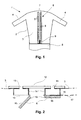
- FIG. 1 shows a device 1 for smoothing shirts, which has a device 6 is equipped to fix the button and buttonhole bar of a shirt 17.
- the Shirt smoothing device 1 has an inflatable bag 2 with a torso section 3 and two adjoining sleeve sections 4 for tensioning the shirt 17.
- the Inflatable bag 2 and the device 6 for fixing the button and buttonhole bar are attached to a base 5, which also serves as a base for the device and in Figure 1 only is partially shown.
- the base 5 has in particular the control for the device and a blower and a heater with which the inflatable bag 2 is inflated with heated air can be.
- the inflatable bag 2 is made of an air-permeable material, through which the heated air can reach a shirt. additionally can be provided that the inflatable bag 2 can also be filled with steam.
- FIG 2 is a horizontal section through the device 6 for fixing the button and the buttonhole bar shown.
- a base plate 12 which is connected to the base 5 is connected, two terminal strips 14 are attached, against which the button strip or the buttonhole of shirt 17 can be clamped.
- the front of the terminal strips 14 are closed with perforated plates 15.
- the terminal strips 14 have openings which correspond to openings in the carrier plate 12 match and form air passages 13.
- the inflatable bag On the outer edges of the carrier plate 12 is the inflatable bag in addition to the terminal strips 14 2 attached with its fuselage section so that air from the inflatable bag 2 through the Passages 13 and the perforated plates 15 up to a clamped on the terminal strips 14 Button bar or buttonhole bar can get.
- Flaps 8 are pivotally attached to the inside of the terminal strips 14, with which the button panel or the buttonhole panel of the shirt 17 against the terminal strips 14 can be pressed.
- the flaps 8 form in the described embodiment the fixing elements and are arranged in two rows 7, which are almost the extend the entire height of the fuselage section 3 of the inflatable bag 2.
- the flaps 8 have an air-permeable clamp body 10, for example made of a porous, foamed Plastic can exist.
- On the side facing the terminal strips 14 the clamping body 10 is covered by a perforated plate 16.
- the perforated plate 16 can Metal or a soft elastic plastic to avoid unevenness Adjust the button or buttonhole bar and in particular buttons sewn onto it to be able to.
- the clamping body 10 is impermeable to air.
- the clamping body 10 itself can be flexible, whereby the perforated plate 16 can be omitted, so that the clamping body 10 directly on the button or Buttonhole bar is pressed.
- the flaps 8 are each assigned spring elements that they from a certain opening angle press into the open position and counter it below this opening angle press the terminal block 14.
- the flaps 8 can individually manually from their open position so far that they snap shut and by the spring be pressed against the terminal block 14.
- a slide 9 is provided, which by means of a Guide bar, not shown, is slidably connected to the base plate 12 and serves as an actuating element for the flaps 8.
- the flaps 8 devices are assigned, which when pushing the Slider 9 from bottom to top closing the flaps beyond the dead center cause.
- the flaps 8 can thus be closed both individually and manually all together by moving the slide 9 from the bottom to the bottom above. It is also provided that when the slide 9 is moved in reverse Direction, that is, from top to bottom, the flaps 8 from their closed Condition brought into the open. Conversely, it can also be provided that the flaps 8 closed when moving the slide 9 from top to bottom and be opened when moving from bottom to top.
- the shirt 17 can be smoothed by heating air from the base 5 the inflatable bag 2 is directed, which then inflates and tightens the shirt 17. there escapes through the permeable material of the inflatable bag 2 to the heated air put on shirt 17 and smooth it. If the shirt 17 is put on when wet, it is dried under tension by the heated air, being a better Smoothing is achieved.
- heated air flows from the inside of the Inflatable bags 2 through the passages 13 in the hollow terminal strips 14 and can through Perforated sheets 15 from the inside to the clamped button or Buttonhole bar. Because of the passages 13 and the perforated plates 15 can also allows better humidification with steam or water or water mist become.
- the solution according to the invention ensures that the shirt 17 to be smoothed by an operator can be fixed quickly and easily, with the possibility of to fix individual areas one after the other, the button and buttonhole placket simply can be aligned straight and without wrinkles.
Landscapes
- Engineering & Computer Science (AREA)
- Textile Engineering (AREA)
- Details Of Garments (AREA)
Claims (10)
- Dispositif (6) pour fixer le bord à boutons et le bord à boutonnières d'une chemise, caractérisé en ce que le dispositif de fixation (6) présente plusieurs éléments de fixation (8), disposés à la suite le long du bord à boutons et/ou du bord à boutonnières, qui peuvent être manipulés individuellement.
- Dispositif selon la revendication 1, caractérisé en ce que le dispositif de fixation (6) présente au moins un élément de manipulation (9) avec lequel un groupe de plusieurs éléments de fixation (8) peut être manipulé en commun.
- Dispositif selon la revendication 1 ou 2, caractérisé en ce que les éléments de fixation (8) s'étendent essentiellement sans intervalles entre eux sur une longueur plus grande que celle du bord à boutons respectivement du bord à boutonnières de chemises normales.
- Dispositif selon l'une d es revendications 1 à 3, caractérisé en ce que les éléments de fixation (8) sont disposés en deux rangées (7) adjacentes, parallèles et en ce que tous les éléments de fixation (8) peuvent être manipulés en commun avec un élément de manipulation (9).
- Dispositif selon l'une des revendications 1 à 4, caractérisé en ce que les éléments de fixation (8) sont conçus comme des rabats pivotants pouvant être amenés manuellement et séparément les uns des autres dans une position de fixation dans laquelle, en étant tendus par un ressort, ils peuvent coincer le bord à boutons et le bord à boutonnières à chaque fois contre une barre de serrage (14), et/ou peuvent être déplacés manuellement et séparément les uns des autres à partir de la position de fixation dans une position de repos stable, dans laquelle les éléments de fixation (8) libèrent le bord à boutons et le bord à boutonnières.
- Dispositif selon la revendication 5, caractérisé en ce que les barres de serrage (14) permettent le passage de l'air vers un bord à boutons respectivement un bord à boutonnières bien serré, en ce que les éléments de fixation (8) présentent un corps de serrage (10) perméable à l'air qui n'est pas perméable à l'air sur les côtés non orientés vers la barre de serrage associée (14).
- Dispositif selon la revendication 5 ou 6, caractérisé en ce que les barres de serrage (14) présentent un canal d'air avec lequel de l'air ne passant pas à travers les barres de serrage (14) peut être dérivé pour récupérer de la chaleur.
- Dispositif selon l'une des revendications 5 à 7, caractérisé en ce qu'il présente des arrangements pour fixer un sac gonflable (2) destiné à tendre la chemise (17) sur les bords externes des barres de serrage (14).
- Dispositif selon la revendication 4, caractérisé en ce que le au moins un élément de manipulation (9) peut être déplacé le long des éléments de fixation (8) et lors du déplacement dans un sens décale les éléments de fixation (8) dans leur état de fixation et lors du déplacement dans l'autre sens les décale de nouveau dans leur état de repos.
- Dispositif selon l'une des revendications 4 à 9, caractérisé en ce que le au moins un élément de manipulation présente pour chaque rangée (7) d'éléments de fixation (8) une tige avec laquelle la rangée associée (7) d'éléments de fixation (8) peut être manipulée par un mouvement de rotation ou de poussée.
Applications Claiming Priority (2)
| Application Number | Priority Date | Filing Date | Title |
|---|---|---|---|
| DE19932452 | 1999-07-12 | ||
| DE19932452A DE19932452A1 (de) | 1999-07-12 | 1999-07-12 | Vorrichtung zum Fixieren der Knopfleiste eines Hemds |
Publications (2)
| Publication Number | Publication Date |
|---|---|
| EP1069229A1 EP1069229A1 (fr) | 2001-01-17 |
| EP1069229B1 true EP1069229B1 (fr) | 2003-10-01 |
Family
ID=7914444
Family Applications (1)
| Application Number | Title | Priority Date | Filing Date |
|---|---|---|---|
| EP00114544A Expired - Lifetime EP1069229B1 (fr) | 1999-07-12 | 2000-07-06 | Dispositif pour maintenir la partie boutonnée d'une chemise |
Country Status (3)
| Country | Link |
|---|---|
| EP (1) | EP1069229B1 (fr) |
| DE (2) | DE19932452A1 (fr) |
| ES (1) | ES2208190T3 (fr) |
Families Citing this family (4)
| Publication number | Priority date | Publication date | Assignee | Title |
|---|---|---|---|---|
| DE10156859A1 (de) * | 2001-11-20 | 2003-05-28 | Bsh Bosch Siemens Hausgeraete | Vorrichtung zum Glätten hemdförmiger Kleidungsstücke |
| DE10339698A1 (de) * | 2003-08-28 | 2005-03-24 | BSH Bosch und Siemens Hausgeräte GmbH | Vorrichtung zum Glätten von Kleidungsstücken mit einer Spannvorrichtung zur Fixierung des Kleidungsstücks |
| DE10339734A1 (de) * | 2003-08-28 | 2005-03-24 | BSH Bosch und Siemens Hausgeräte GmbH | Vorrichtung zum Glätten von Kleidungstücken mit Spannkörpern zur Fixierung eines Kleidungsstücks |
| DE10339736A1 (de) * | 2003-08-28 | 2005-03-24 | BSH Bosch und Siemens Hausgeräte GmbH | Vorrichtung zum Glätten von Kleidungsstücken mit Spannkörpern zur Fixierung des Kleidungsstücks |
Family Cites Families (14)
| Publication number | Priority date | Publication date | Assignee | Title |
|---|---|---|---|---|
| US2361045A (en) * | 1941-08-07 | 1944-10-24 | Us Hoffman Machinery Corp | Garment processing apparatus |
| US2353741A (en) * | 1943-02-20 | 1944-07-18 | American Laundry Mach Co | Garment drier |
| US2417838A (en) * | 1945-02-12 | 1947-03-25 | August F Paris | Garment finishing apparatus |
| US2740566A (en) * | 1951-04-02 | 1956-04-03 | Bill Glover Inc | Shirt finishing machine |
| US3151860A (en) * | 1959-12-31 | 1964-10-06 | Martin R Dosal | Garment holder |
| US3066839A (en) * | 1960-08-24 | 1962-12-04 | Martin R Dosal | Apparatus for pressing shirts |
| US3165244A (en) * | 1962-05-18 | 1965-01-12 | Dosal Martin Roberto | Inflatable apparatus for pressing shirts |
| US3194456A (en) * | 1964-01-22 | 1965-07-13 | Ametek Inc | Shirt-clamping mechanism |
| US3568900A (en) * | 1969-10-27 | 1971-03-09 | August F Paris | Shirt pressing machine |
| US3613969A (en) * | 1970-05-05 | 1971-10-19 | Harry D Forse | Shirt press |
| FR2337779A1 (fr) * | 1976-01-09 | 1977-08-05 | Rebiscoul Gerard | Perfectionnement pour formes de mannequin d'appret ou de repassage pour tous vetements a ouverture centrale sur le devant |
| GB2225592A (en) * | 1988-11-23 | 1990-06-06 | Everett Dev Ltd | Garment pressing apparatus |
| IT233390Y1 (it) * | 1994-04-29 | 2000-01-28 | Dalf S N C Di Pessina Enzo & C | Macchina perfezionata,particolarmente studiata per la stiratura di capi di vestiario come camicie o simili |
| DE19754026A1 (de) * | 1997-12-05 | 1999-06-10 | Bosch Siemens Hausgeraete | Vorrichtung zum Glätten von Hemden |
-
1999
- 1999-07-12 DE DE19932452A patent/DE19932452A1/de not_active Withdrawn
-
2000
- 2000-07-06 EP EP00114544A patent/EP1069229B1/fr not_active Expired - Lifetime
- 2000-07-06 ES ES00114544T patent/ES2208190T3/es not_active Expired - Lifetime
- 2000-07-06 DE DE50003882T patent/DE50003882D1/de not_active Expired - Lifetime
Also Published As
| Publication number | Publication date |
|---|---|
| EP1069229A1 (fr) | 2001-01-17 |
| ES2208190T3 (es) | 2004-06-16 |
| DE19932452A1 (de) | 2001-01-18 |
| DE50003882D1 (de) | 2003-11-06 |
Similar Documents
| Publication | Publication Date | Title |
|---|---|---|
| EP1349981B1 (fr) | Dispositif de lissage de chemises | |
| EP1069229B1 (fr) | Dispositif pour maintenir la partie boutonnée d'une chemise | |
| EP1349979A1 (fr) | Dispositif de defroissage de chemises | |
| EP1349980B1 (fr) | Mannequin de repassage comportant un renforcement a l'extremite de la manche | |
| EP1600550A1 (fr) | Dispositif pour serrer les extrémités d'un ourlet et dispositif pour sécher et/ou lisser des vêtements | |
| EP1069231B1 (fr) | Dispositif pour le lissage de chemise | |
| EP1448833A2 (fr) | Dispositif pour lisser des vetements sous forme de chemises | |
| EP1510614B1 (fr) | Dispositif pour lisser des vêtements | |
| WO1995002503A1 (fr) | Dispositif permettant de produire un revetement de protection pour abattant de w.-c. | |
| WO2005028739A1 (fr) | Dispositif de repassage de vetements comportant un corps gonflant flexible et un dispositif d'etirage | |
| EP1069230B1 (fr) | Dispositif pour le lissage de chemise avec col | |
| DE2723596A1 (de) | Buegelvorrichtung | |
| EP1448834A1 (fr) | Corps gonflant pour lisser des vetements sous forme de chemises et dispositif pour lisser des vetements pourvus d'un tel corps gonflant | |
| EP1528142A2 (fr) | Dispositif de fixation pour fixer une manchette d'un vêtement à un dispositif de défroissage du vêtement et procédé de fixation correspondant | |
| EP0881317B1 (fr) | Finisseur | |
| EP1339908A1 (fr) | Dispositif de defroissage de chemises | |
| DE202024102063U1 (de) | Kleiderbügel | |
| DE1960655C (de) | Dämpf- und Blaspuppe | |
| DE202004008892U1 (de) | Bügelvorrichtung für Oberbekleidungsstücke wie z.B. Hemden, Blusen u.dgl. | |
| DE202004008896U1 (de) | Bügelvorrichtung für Oberbekleidungsstücke wie z.B. Hemden, Blusen u.dgl. | |
| DE10339781A1 (de) | Vorrichtung zum Glätten von Kleidungsstücken mit Kragen | |
| DE20020231U1 (de) | Vorrichtung zum Glätten von Hemden mit Kragen | |
| WO2005024117A1 (fr) | Dispositif de lissage d'un vetement | |
| DE1257732B (de) | Buegelpresse fuer Hosen | |
| DE3121554A1 (de) | Maschine zum buegeln von hosen in vertikallage |
Legal Events
| Date | Code | Title | Description |
|---|---|---|---|
| PUAI | Public reference made under article 153(3) epc to a published international application that has entered the european phase |
Free format text: ORIGINAL CODE: 0009012 |
|
| AK | Designated contracting states |
Kind code of ref document: A1 Designated state(s): DE ES FR GB IT SE |
|
| AX | Request for extension of the european patent |
Free format text: AL;LT;LV;MK;RO;SI |
|
| RIN1 | Information on inventor provided before grant (corrected) |
Inventor name: WETZL, GERHARD Inventor name: DAMRATH, JOACHIM Inventor name: NAUTA, WILHELM Inventor name: SPIELMANNLEITNER, MARKUS |
|
| 17P | Request for examination filed |
Effective date: 20010214 |
|
| AKX | Designation fees paid |
Free format text: DE ES FR GB IT SE |
|
| 17Q | First examination report despatched |
Effective date: 20020910 |
|
| GRAH | Despatch of communication of intention to grant a patent |
Free format text: ORIGINAL CODE: EPIDOS IGRA |
|
| GRAS | Grant fee paid |
Free format text: ORIGINAL CODE: EPIDOSNIGR3 |
|
| GRAA | (expected) grant |
Free format text: ORIGINAL CODE: 0009210 |
|
| AK | Designated contracting states |
Kind code of ref document: B1 Designated state(s): DE ES FR GB IT SE |
|
| REG | Reference to a national code |
Ref country code: GB Ref legal event code: FG4D Free format text: NOT ENGLISH |
|
| REF | Corresponds to: |
Ref document number: 50003882 Country of ref document: DE Date of ref document: 20031106 Kind code of ref document: P |
|
| RAP2 | Party data changed (patent owner data changed or rights of a patent transferred) |
Owner name: BSH BOSCH UND SIEMENS HAUSGERAETE GMBH |
|
| REG | Reference to a national code |
Ref country code: SE Ref legal event code: TRGR |
|
| GBT | Gb: translation of ep patent filed (gb section 77(6)(a)/1977) |
Effective date: 20040122 |
|
| ET | Fr: translation filed | ||
| REG | Reference to a national code |
Ref country code: ES Ref legal event code: FG2A Ref document number: 2208190 Country of ref document: ES Kind code of ref document: T3 |
|
| PLBE | No opposition filed within time limit |
Free format text: ORIGINAL CODE: 0009261 |
|
| STAA | Information on the status of an ep patent application or granted ep patent |
Free format text: STATUS: NO OPPOSITION FILED WITHIN TIME LIMIT |
|
| 26N | No opposition filed |
Effective date: 20040702 |
|
| PGFP | Annual fee paid to national office [announced via postgrant information from national office to epo] |
Ref country code: SE Payment date: 20120723 Year of fee payment: 13 Ref country code: GB Payment date: 20120723 Year of fee payment: 13 |
|
| PGFP | Annual fee paid to national office [announced via postgrant information from national office to epo] |
Ref country code: FR Payment date: 20120803 Year of fee payment: 13 Ref country code: IT Payment date: 20120725 Year of fee payment: 13 Ref country code: DE Payment date: 20120731 Year of fee payment: 13 Ref country code: ES Payment date: 20120723 Year of fee payment: 13 |
|
| REG | Reference to a national code |
Ref country code: SE Ref legal event code: EUG |
|
| GBPC | Gb: european patent ceased through non-payment of renewal fee |
Effective date: 20130706 |
|
| REG | Reference to a national code |
Ref country code: FR Ref legal event code: ST Effective date: 20140331 |
|
| PG25 | Lapsed in a contracting state [announced via postgrant information from national office to epo] |
Ref country code: GB Free format text: LAPSE BECAUSE OF NON-PAYMENT OF DUE FEES Effective date: 20130706 Ref country code: DE Free format text: LAPSE BECAUSE OF NON-PAYMENT OF DUE FEES Effective date: 20140201 Ref country code: SE Free format text: LAPSE BECAUSE OF NON-PAYMENT OF DUE FEES Effective date: 20130707 |
|
| REG | Reference to a national code |
Ref country code: DE Ref legal event code: R119 Ref document number: 50003882 Country of ref document: DE Effective date: 20140201 |
|
| PG25 | Lapsed in a contracting state [announced via postgrant information from national office to epo] |
Ref country code: FR Free format text: LAPSE BECAUSE OF NON-PAYMENT OF DUE FEES Effective date: 20130731 Ref country code: IT Free format text: LAPSE BECAUSE OF NON-PAYMENT OF DUE FEES Effective date: 20130706 |
|
| REG | Reference to a national code |
Ref country code: ES Ref legal event code: FD2A Effective date: 20141010 |
|
| PG25 | Lapsed in a contracting state [announced via postgrant information from national office to epo] |
Ref country code: ES Free format text: LAPSE BECAUSE OF NON-PAYMENT OF DUE FEES Effective date: 20130707 |