EP1069224B1 - Aiguille de feutrage - Google Patents
Aiguille de feutrage Download PDFInfo
- Publication number
- EP1069224B1 EP1069224B1 EP00109536A EP00109536A EP1069224B1 EP 1069224 B1 EP1069224 B1 EP 1069224B1 EP 00109536 A EP00109536 A EP 00109536A EP 00109536 A EP00109536 A EP 00109536A EP 1069224 B1 EP1069224 B1 EP 1069224B1
- Authority
- EP
- European Patent Office
- Prior art keywords
- transition
- needle
- felting needle
- working part
- region
- Prior art date
- Legal status (The legal status is an assumption and is not a legal conclusion. Google has not performed a legal analysis and makes no representation as to the accuracy of the status listed.)
- Expired - Lifetime
Links
- 238000009950 felting Methods 0.000 title claims description 22
- 230000007704 transition Effects 0.000 claims description 55
- 230000007423 decrease Effects 0.000 claims description 4
- 239000000835 fiber Substances 0.000 description 28
- 238000004140 cleaning Methods 0.000 description 5
- 239000000463 material Substances 0.000 description 5
- 238000004519 manufacturing process Methods 0.000 description 3
- 238000000034 method Methods 0.000 description 3
- 230000008569 process Effects 0.000 description 3
- 230000035508 accumulation Effects 0.000 description 2
- 238000009825 accumulation Methods 0.000 description 2
- 239000004745 nonwoven fabric Substances 0.000 description 2
- 230000009467 reduction Effects 0.000 description 2
- 230000002411 adverse Effects 0.000 description 1
- 230000008901 benefit Effects 0.000 description 1
- 230000015572 biosynthetic process Effects 0.000 description 1
- 230000008859 change Effects 0.000 description 1
- 238000005137 deposition process Methods 0.000 description 1
- 230000000694 effects Effects 0.000 description 1
- 239000002557 mineral fiber Substances 0.000 description 1
- 239000000203 mixture Substances 0.000 description 1
- 230000000149 penetrating effect Effects 0.000 description 1
- 238000001556 precipitation Methods 0.000 description 1
- 239000007787 solid Substances 0.000 description 1
- 239000012209 synthetic fiber Substances 0.000 description 1
- 229920002994 synthetic fiber Polymers 0.000 description 1
Images


Classifications
-
- D—TEXTILES; PAPER
- D04—BRAIDING; LACE-MAKING; KNITTING; TRIMMINGS; NON-WOVEN FABRICS
- D04H—MAKING TEXTILE FABRICS, e.g. FROM FIBRES OR FILAMENTARY MATERIAL; FABRICS MADE BY SUCH PROCESSES OR APPARATUS, e.g. FELTS, NON-WOVEN FABRICS; COTTON-WOOL; WADDING ; NON-WOVEN FABRICS FROM STAPLE FIBRES, FILAMENTS OR YARNS, BONDED WITH AT LEAST ONE WEB-LIKE MATERIAL DURING THEIR CONSOLIDATION
- D04H18/00—Needling machines
- D04H18/02—Needling machines with needles
Definitions
- the invention relates to a needle having the features of the preamble of patent claim 1 or claim 2.
- Deposits form after a certain period of the machine for producing the felt.
- the deposits can clog the needles to such an extent that the needles are no longer able to penetrate through the holes of the stripper plate.
- These deposits cause needle breaks and production losses.
- the air flow between the needles is adversely affected, with the result that the deposits accelerate even more.
- the production must be interrupted. Needle cleaning often results in needle breakage.
- the material is solidified.
- the material is relatively loose and voluminous. Penetrating the needle with its shank portion or its intermediate portion in the material, it produces holes with shaft diameter or the diameter of the intermediate portion, which is greater than the diameter of the working part. This results in a poor surface quality of the felt.
- Felt needles are known with a long straight shaft, which is angled at its upper end for clamping in a needle board.
- the shank tapers at its other end to a reduced cross section and is further provided with hooks.
- This Section forms a working part that serves to matt the fiber fleece.
- a device for needling a mineral fiber fleece is known.
- the felting needles held on a needle board extend parallel to each other away from the needle board through corresponding openings of a stripper plate. Between this and a bed plate, which also has openings for the felting needles, a gap is formed through which the nonwoven fabric is guided.
- the felting needles have a cylindrical, upwardly angled and relatively thick shaft, of which a portion is held in the needle board. Between the clamping part and the toothed working part, a transition region is formed whose length is barely larger than the diameter of the shaft region.
- Deposits can form on the cylindrical shaft.
- a forked needle which has a unge leopardten workspace. This connects via a conical intermediate region to a cylindrical shaft.
- the working part is smooth on its outside and provided only at its free end with a mouth-like fork.
- a more or less steep transition region may be provided in the form of a cone.
- Forked needles are used to structure consolidated webs in a sequential process. They tend because of the smooth ungebergten edges of the working part little to dissolve fibers from the fiber structure and take.
- Felting needles with a serrated working part tend to accumulate fibers pulled out of the fiber structure on their shafts.
- the shaft extends during needling of the fibers partially in the working space between stripper plate and bed plate.
- the extracted fibers form deposits in the form of fiber rings which slide from the relatively thin working part over the short transition region to the cylindrical shaft region between the needle board and the stripper plate. They are widened and tightened. If these deposits exceed a tolerable level, the piercing of the needles into the fleece is hindered because the needle board can no longer be brought close enough to the stripper plate. Therefore, depending on the nonwoven material used, cleaning actions are required from time to time. Due to the large number of needles held on a needle board, such cleaning is cumbersome and time consuming.
- the needle according to the invention is characterized in that a relatively slender transition part or transition region is formed between the toothed working part and the untoothed clamping part, which has at least one region in which the diameter gradually reduces from the shaft diameter to the diameter of the working part.
- the length of this area which may also be divided into several subregions as needed, is at least twice as long as the length of the toothed working part.
- the length of the transition region with conventional needle board thicknesses or thicknesses is greater than the respective thickness of the needle board.
- the transition part preferably occupies the entire space between the needle board and the respective working part. The result is a slim transition, which results in less deposits forming on the needle.
- the precipitation rings made of fibers expand only slowly, which results in less adhesion to the transition area.
- the cleaning of the respective needles by the long transition part is easier.
- Flush rings sitting on the needles and fiber accumulations between the needles are easier to wipe or remove from the needle.
- the working part of the needle can be made slimmer than conventional needles.
- the transition is preferably longer 11, better still 20 mm.
- the needle according to the invention can replace felting needles with single, double or triple diameter reduction. This reduces the variety of types to be provided by the needle manufacturer.
- shank area which passes between the stripper plate and bed plate during needling, has a smaller diameter compared to conventional needles.
- the openings produced by the shaft region in the felt produced in the diameter are smaller.
- the surface quality of the felt improves.
- the transition part is preferably formed conically in a continuous part.
- the cone can be a straight circle truncated cone. This means that a generating line of this area is a straight line.
- the cone may also be formed by a non-straight cone. A generatrix of the transition part is then arcuate.
- the working part and the clamping part are preferably arranged coaxially relative to one another. If necessary, however, it can also deviate from this become.
- the working part has a constant diameter and also connects preferably without diameter change smoothly to the transition part.
- the transition part occupies the entire space between the needle board and the working part.
- the total length of the transition part may be smaller than twice the working part length due to the needle dimensions.
- the needle consists of three areas: working part, transition part and shaft part, which sits completely in the needle board.
- transition part is longer than the thickness of the needle board provided for attachment of the needles. Regardless of the overall length of the transition piece, in one embodiment of the needle, the transition piece begins immediately on the needle board.
- FIG. 1 illustrates a device 1 for needling a nonwoven fabric.
- a needle board 2 which is driven, for example. Via an eccentric and performs a reciprocating motion in a direction illustrated by an arrow 3 direction.
- the needle board 2 has openings 4 for holding and supporting needles 5.
- the needles 5 extend at a distance and parallel to each other from the needle board 2 away. They protrude through wiper openings 6, which are formed in a stripper plate 7. This is arranged at some distance from a bed plate 8 and defines with this a gap 9, are guided by the loose and disordered fibers in a direction indicated in Figure 1 by an arrow 11 direction. In the course of these fibers are solidified by the up and down movement of the needles 5 to form a nonwoven.
- openings 12 are provided, wherein in each case an opening 12 of the bed plate 8 is aligned with an opening 6 of the stripper plate 7.
- the needles 5 are constructed to match each other. They each have a clamping part 14 held in the needle board 2 and a working part 16 provided with barbs or hooks 15. Between the Einspannteil 14 and the working part 16, a transition part 17 is arranged. The transition part 17 extends from the chucking part 14 to the working part 16, starting in the immediate vicinity of the needle board 2.
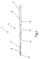
- FIG. 2 shows a needle 5 for the purpose of illustrating the proportions.
- the diameter decreases from the larger value to be measured at the transition point 18 to a lower value to be measured at a transition point 19 at which the working part 16 begins.
- the transition piece 17 is arranged coaxially to a longitudinal axis 21 of the needle 5 and forms a total of a contiguous area for the adjustment of the diameter.
- the clamping part 14 and the working part 16 are arranged coaxially with the longitudinal axis 21. Along the longitudinal axis 21, the diameter of the transition part 17 decreases steadily and linearly.
- the between the transition points 18, 19 to be measured length of the transition part 17 is at least twice as large as the length of the working part 16, ie the distance of the transition point 19 formed by a free end of the needle 5 tip 22. This makes the transition part is very slim and long. He has no steps or heels.
- the device 1 operates as follows:
- FIG. 3 illustrates a somewhat modified embodiment of the needle 5.
- the region formed by the transition part 17 is divided into two subregions 17a, 17b, in which the diameter of the needle 5 is reduced from the shaft diameter to the working part diameter.
- the partial area 17a adjoins the transition point 19, while the partial area 17b adjoins the transition point 18.
- a cylindrical intermediate section 17c is formed between the sections 17a, 17b.
- the transition part 17 begins immediately after the needle board 2, ie that the transition point 18 is aligned with the underside of the needle board 2.
- the portions 17a, 17b, in which the taper of the needle 5 takes place, taken together have a length which is equal to or greater than twice the length of the working part 16, ie the distance between the transition point 19 and the top 22nd
- the portions 17a, 17b are each on the mantle of a narrow cone, i. the diameter decreases in these partial regions 17a, 17b towards the tip 22.
- the diameter reduction is linear in the embodiment of FIG. 4 for the portion 17a, not for the portion 17b.
- the trained cone is thus curvilinearly limited.
- Such a cone may also be formed instead of the cone in the portion 17a or in the embodiment of Figure 2 instead of the straight slender truncated cone in the transition part 17.
- a transition part 17 is provided between clamping part 14 and working part 16, which is designed as a long slender truncated cone.
- the length of this transition part 17 is at least twice as long as the working part. This results in a very slim transition region, which has little tendency to pull fibers from the fleece and collect. If fiber deposits nevertheless form, these are easy to remove.
Landscapes
- Engineering & Computer Science (AREA)
- Textile Engineering (AREA)
- Nonwoven Fabrics (AREA)
Claims (12)
- Aiguille de feutrage (5) destinée à être fixée à une planche à aiguilles (2), comprenant
un corps d'aiguille allongé, sur lequel sont réalisées une portion de serrage (14) et une portion de travail (16) pourvue de barbes (15) sur sa longueur, la portion de serrage (14) présentant un diamètre supérieur à celui de la portion de travail (16),
une portion de transition (17) qui est formée entre la portion de travail (16) et la portion de serrage (14) et dans laquelle est aménagée une zone (17, 17a, 17b) dans laquelle le diamètre diminue pour passer du diamètre de la portion de serrage (14) au diamètre de la portion de travail (16),
caractérisée par le fait que la zone (17, 17a, 17b) présente globalement une longueur qui est égale ou supérieure au double de la longueur de la portion de travail (16). - Aiguille de feutrage selon la revendication 1, caractérisée par le fait que la zone (17, 17a, 17b) s'étend de la portion de serrage (14), dont la longueur est déterminée par l'épaisseur de la planche à aiguilles, jusqu'à la portion de travail (16).
- Aiguille de feutrage selon la revendication 1, caractérisée par le fait que la longueur de la portion de transition (17) est supérieure à 11 mm.
- Aiguille de feutrage selon la revendication 3, caractérisée par le fait que la longueur de la portion de transition est supérieure à 20 mm.
- Aiguille de feutrage selon la revendication 1, 2 ou 3, caractérisée par le fait que la portion (17, 17a, 17b) est conformée en cône.
- Aiguille de feutrage selon la revendication 1, 2 ou 3, caractérisée par le fait que la portion (17) est répartie sur au moins deux zones partielles (17a, 17b) coniques.
- Aiguille de feutrage selon la revendication 5 ou 6, caractérisée par le fait que les portions (17) coniques ou les zones partielles (17a, 17b) sont des troncs de cônes de révolution rectilignes.
- Aiguille de feutrage selon la revendication 5 ou 6, caractérisée par le fait que la portion conique (17) ou les zones partielles (17a, 17b) sont des troncs de cônes de révolution à génératrices curvilignes.
- Aiguille de feutrage selon la revendication 1, 2 ou 3, caractérisée par le fait que la portion de travail (16) et la portion de serrage (14) sont disposées de façon coaxiale l'une avec l'autre.
- Aiguille de feutrage selon la revendication 1, 2, ou 3, caractérisée par le fait que la portion de travail (16) présente un diamètre constant.
- Aiguille de feutrage selon la revendication 1, 2, ou 3, caractérisée par le fait que la portion de serrage (14) présente un diamètre constant.
- Aiguille de feutrage selon la revendication 1, 2, ou 3, caractérisée par le fait que la portion de serrage (14) et la portion de transition (17) présentent une section circulaire.
Applications Claiming Priority (2)
| Application Number | Priority Date | Filing Date | Title |
|---|---|---|---|
| US352369 | 1999-07-13 | ||
| US09/352,369 US6233797B1 (en) | 1999-07-13 | 1999-07-13 | Felt needle |
Publications (2)
| Publication Number | Publication Date |
|---|---|
| EP1069224A1 EP1069224A1 (fr) | 2001-01-17 |
| EP1069224B1 true EP1069224B1 (fr) | 2007-06-27 |
Family
ID=23384854
Family Applications (1)
| Application Number | Title | Priority Date | Filing Date |
|---|---|---|---|
| EP00109536A Expired - Lifetime EP1069224B1 (fr) | 1999-07-13 | 2000-05-04 | Aiguille de feutrage |
Country Status (5)
| Country | Link |
|---|---|
| US (1) | US6233797B1 (fr) |
| EP (1) | EP1069224B1 (fr) |
| JP (1) | JP3566187B2 (fr) |
| DE (1) | DE50014437D1 (fr) |
| ES (1) | ES2288815T3 (fr) |
Families Citing this family (24)
| Publication number | Priority date | Publication date | Assignee | Title |
|---|---|---|---|---|
| GB0402131D0 (en) | 2004-01-30 | 2004-03-03 | Isis Innovation | Delivery method |
| DE102004037716B4 (de) * | 2004-08-04 | 2009-04-02 | Groz-Beckert Kg | Nachbehandlungsnadel für textile Flächengebilde |
| FR2885621B1 (fr) * | 2005-05-16 | 2007-08-10 | Duflot Ind Sa | Aiguille sans barre pour aiguilleteuse, son utilisation et produit complexe aiguillete et perfore obtenu |
| US20070044696A1 (en) * | 2005-08-31 | 2007-03-01 | Chih-Po Yang | Needle for stereographic embroidery |
| ES2322159T3 (es) * | 2005-12-27 | 2009-06-17 | Groz-Beckert Kg | Aguja de fieltrar. |
| EP1953287B1 (fr) * | 2007-02-02 | 2014-01-15 | Groz-Beckert KG | Procédé et dispositif destinés à l'implantation de planches à pointes pour machines de feutrage |
| EP2218814B1 (fr) * | 2009-02-12 | 2011-05-04 | Groz-Beckert KG | Aiguille pour une machine textile |
| US8251262B2 (en) * | 2009-08-12 | 2012-08-28 | Timothy Peckels | Volume metered pour spout |
| AU2012323782B2 (en) | 2011-10-12 | 2017-04-06 | Vaxxas Pty Limited | Delivery device |
| CN103938369A (zh) * | 2014-04-11 | 2014-07-23 | 吴江龙升纺织有限公司 | 一种纤网加固装置 |
| US11147954B2 (en) | 2015-02-02 | 2021-10-19 | Vaxxas Pty Limited | Microprojection array applicator and method |
| US11103259B2 (en) | 2015-09-18 | 2021-08-31 | Vaxxas Pty Limited | Microprojection arrays with microprojections having large surface area profiles |
| EP3355981B1 (fr) | 2015-09-28 | 2025-11-19 | Vaxxas Pty Limited | Réseau de microsaillies ayant des propriétés de pénétration de la peau améliorées et procédés associés |
| AU2018241251B2 (en) | 2017-03-31 | 2024-06-27 | Vaxxas Pty Limited | Device and method for coating surfaces |
| US11175128B2 (en) | 2017-06-13 | 2021-11-16 | Vaxxas Pty Limited | Quality control of substrate coatings |
| CA3071680A1 (fr) | 2017-08-04 | 2019-02-07 | Vaxxas Pty Limited | Actionneur a stockage d'energie mecanique eleve compact et a force de declenchement faible pour l'administration de patchs a reseaux de microprojections (prm) |
| US12404616B2 (en) | 2022-10-31 | 2025-09-02 | Rohr, Inc. | Systems and methods for robotic arm end effector for tailored through thickness reinforcement |
| US12297572B2 (en) * | 2022-10-31 | 2025-05-13 | Rohr, Inc. | Systems and methods for self-cleaning needles for through thickness reinforcement of resin-infused fabrics |
| US12297571B2 (en) | 2022-10-31 | 2025-05-13 | Rohr, Inc. | Systems and methods for spray cleaning needles for through thickness reinforcement of resin-infused fabrics |
| US12545628B2 (en) | 2023-03-17 | 2026-02-10 | Rtx Corporation | Sheathed metallic needles for producing z-channels in fibrous preforms |
| US20240308922A1 (en) * | 2023-03-17 | 2024-09-19 | Raytheon Technologies Corporation | Tooling for producing z-channels in ceramic fiber preforms |
| DE102023119894A1 (de) | 2023-07-27 | 2025-01-30 | Voith Patent Gmbh | Verfahren und Vorrichtung |
| DE102023119892A1 (de) | 2023-07-27 | 2025-01-30 | Voith Patent Gmbh | Verfahren und Filz |
| EP4663826B1 (fr) * | 2024-06-13 | 2026-03-11 | Groz-Beckert KG | Aiguille de feutre, plaque à aiguilles pour une machine de feutre et procédé d'introduction d'une aiguille de feutre dans une plaque à aiguilles |
Family Cites Families (12)
| Publication number | Priority date | Publication date | Assignee | Title |
|---|---|---|---|---|
| BE536394A (fr) * | 1954-03-10 | 1900-01-01 | ||
| NL110401C (fr) | 1954-03-10 | |||
| US2883585A (en) * | 1954-06-15 | 1959-04-21 | Westinghouse Electric Corp | Circuit breaker |
| DE1265426B (de) * | 1964-04-15 | 1968-04-04 | J J Marx Fa | Nadelbrett fuer Nadelfilzmaschinen und Verfahren zu seiner Bestueckung mit Nadeln |
| US3347192A (en) * | 1965-05-24 | 1967-10-17 | Union Special Machine Co | Sewing machine needle |
| US3464097A (en) | 1967-06-01 | 1969-09-02 | Singer Co | Felting needle |
| US3542632A (en) * | 1969-02-28 | 1970-11-24 | Standard Oil Co | Fibrillated fabrics and a process for the preparation thereof |
| US3877120A (en) * | 1970-02-20 | 1975-04-15 | Toray Industries | Needle board |
| US3727276A (en) * | 1971-04-06 | 1973-04-17 | E Foster | Felting needle |
| US3753412A (en) * | 1971-12-02 | 1973-08-21 | Torrington Co | Selectively hardened needles |
| US3844004A (en) | 1973-09-20 | 1974-10-29 | E Foster | Felting needle |
| US4131978A (en) | 1977-11-09 | 1979-01-02 | The Singer Company | Felting needle |
-
1999
- 1999-07-13 US US09/352,369 patent/US6233797B1/en not_active Expired - Lifetime
-
2000
- 2000-05-04 EP EP00109536A patent/EP1069224B1/fr not_active Expired - Lifetime
- 2000-05-04 DE DE50014437T patent/DE50014437D1/de not_active Expired - Lifetime
- 2000-05-04 ES ES00109536T patent/ES2288815T3/es not_active Expired - Lifetime
- 2000-07-11 JP JP2000210172A patent/JP3566187B2/ja not_active Expired - Lifetime
Non-Patent Citations (1)
| Title |
|---|
| None * |
Also Published As
| Publication number | Publication date |
|---|---|
| JP2001040567A (ja) | 2001-02-13 |
| US6233797B1 (en) | 2001-05-22 |
| DE50014437D1 (de) | 2007-08-09 |
| EP1069224A1 (fr) | 2001-01-17 |
| ES2288815T3 (es) | 2008-02-01 |
| JP3566187B2 (ja) | 2004-09-15 |
Similar Documents
| Publication | Publication Date | Title |
|---|---|---|
| EP1069224B1 (fr) | Aiguille de feutrage | |
| DE10232148B4 (de) | Verfahren zum flüssigkeitsdurchlässigen Perforieren eines Vlieses | |
| AT394401B (de) | Einrichtung an nadelmaschinen zur herstellung von nadelfilzbahnen od. dgl. | |
| EP2138616A1 (fr) | Planche à aiguilles pour une aiguilleteuse | |
| DE1560701C3 (de) | Vorrichtung zur Herstellung eines ungewebten Faserstoffes | |
| DE60003081T2 (de) | Vorrichtung zu hydraulischer vernadelung von bahnförmigen materialen | |
| EP3061855B1 (fr) | Installation de carde et procede de renforcement d'un voile de carde | |
| DE19640750B4 (de) | Vorrichtung zum Nadeln eines Vlieses | |
| DE19819733A1 (de) | Vorrichtung zum Nadeln eines Vlieses | |
| EP0363707A2 (fr) | Procédé de fabrication d'un feutre aiguilleté en laine de laitier | |
| EP1806444B1 (fr) | Aiguille à feutrer | |
| AT501434B1 (de) | Vlieszuführvorrichtung | |
| DE19713350C2 (de) | Vorrichtung zur Vernadelung eines vorverfestigten Vlieses | |
| EP1871937B1 (fr) | Dispositif pour creer un motif et pour consolider une bande de materiau comportant un manchon interchangeable ayant un motif | |
| WO2015135982A1 (fr) | Fil métallique de garniture de carde et procédé de fabrication de nappes de fibres discontinues | |
| WO2008110134A1 (fr) | Dispositif de consolidation de fibres discontinues ou d'un non-tissé constitué de filaments | |
| EP1191135A2 (fr) | Courroies pour banc à étirer à courroies doublées | |
| AT404144B (de) | Vorrichtung zum vorvernadeln eines faservlieses | |
| EP4043629B1 (fr) | Dispositif d'aspiration d'un fluide dans une installation de fabrication de non-tissé | |
| AT406391B (de) | Vorrichtung zum nadeln eines vlieses | |
| AT407059B (de) | Vorrichtung zum nadeln eines vlieses | |
| AT404143B (de) | Vorrichtung zur oberflächenvernadelung eines vlieses | |
| EP0924329B1 (fr) | Dispositif et procédé d'aiguilletage de matériaux non-tissés en vue de fabriquer une nappe fibreuse isolante | |
| CH696072A5 (de) | Vorrichtung zum Verfestigen eines förderbaren Faservlieses. | |
| AT405303B (de) | Vorrichtung zum nadeln einer vorverfestigten vliesbahn |
Legal Events
| Date | Code | Title | Description |
|---|---|---|---|
| PUAI | Public reference made under article 153(3) epc to a published international application that has entered the european phase |
Free format text: ORIGINAL CODE: 0009012 |
|
| AK | Designated contracting states |
Kind code of ref document: A1 Designated state(s): DE ES FR GB IT |
|
| AX | Request for extension of the european patent |
Free format text: AL;LT;LV;MK;RO;SI |
|
| 17P | Request for examination filed |
Effective date: 20010618 |
|
| AKX | Designation fees paid |
Free format text: DE ES FR GB IT |
|
| 17Q | First examination report despatched |
Effective date: 20040819 |
|
| GRAP | Despatch of communication of intention to grant a patent |
Free format text: ORIGINAL CODE: EPIDOSNIGR1 |
|
| GRAS | Grant fee paid |
Free format text: ORIGINAL CODE: EPIDOSNIGR3 |
|
| GRAA | (expected) grant |
Free format text: ORIGINAL CODE: 0009210 |
|
| AK | Designated contracting states |
Kind code of ref document: B1 Designated state(s): DE ES FR GB IT |
|
| REG | Reference to a national code |
Ref country code: GB Ref legal event code: FG4D Free format text: NOT ENGLISH |
|
| REF | Corresponds to: |
Ref document number: 50014437 Country of ref document: DE Date of ref document: 20070809 Kind code of ref document: P |
|
| ET | Fr: translation filed | ||
| GBT | Gb: translation of ep patent filed (gb section 77(6)(a)/1977) |
Effective date: 20070920 |
|
| REG | Reference to a national code |
Ref country code: ES Ref legal event code: FG2A Ref document number: 2288815 Country of ref document: ES Kind code of ref document: T3 |
|
| PLBE | No opposition filed within time limit |
Free format text: ORIGINAL CODE: 0009261 |
|
| STAA | Information on the status of an ep patent application or granted ep patent |
Free format text: STATUS: NO OPPOSITION FILED WITHIN TIME LIMIT |
|
| 26N | No opposition filed |
Effective date: 20080328 |
|
| PGFP | Annual fee paid to national office [announced via postgrant information from national office to epo] |
Ref country code: GB Payment date: 20120522 Year of fee payment: 13 |
|
| PGFP | Annual fee paid to national office [announced via postgrant information from national office to epo] |
Ref country code: ES Payment date: 20120525 Year of fee payment: 13 |
|
| GBPC | Gb: european patent ceased through non-payment of renewal fee |
Effective date: 20130504 |
|
| PG25 | Lapsed in a contracting state [announced via postgrant information from national office to epo] |
Ref country code: GB Free format text: LAPSE BECAUSE OF NON-PAYMENT OF DUE FEES Effective date: 20130504 |
|
| REG | Reference to a national code |
Ref country code: ES Ref legal event code: FD2A Effective date: 20140606 |
|
| PG25 | Lapsed in a contracting state [announced via postgrant information from national office to epo] |
Ref country code: ES Free format text: LAPSE BECAUSE OF NON-PAYMENT OF DUE FEES Effective date: 20130505 |
|
| REG | Reference to a national code |
Ref country code: FR Ref legal event code: PLFP Year of fee payment: 17 |
|
| REG | Reference to a national code |
Ref country code: FR Ref legal event code: PLFP Year of fee payment: 18 |
|
| REG | Reference to a national code |
Ref country code: FR Ref legal event code: PLFP Year of fee payment: 19 |
|
| PGFP | Annual fee paid to national office [announced via postgrant information from national office to epo] |
Ref country code: FR Payment date: 20190313 Year of fee payment: 20 |
|
| PGFP | Annual fee paid to national office [announced via postgrant information from national office to epo] |
Ref country code: DE Payment date: 20190531 Year of fee payment: 20 Ref country code: IT Payment date: 20190527 Year of fee payment: 20 |
|
| REG | Reference to a national code |
Ref country code: DE Ref legal event code: R071 Ref document number: 50014437 Country of ref document: DE |