EP1069079B1 - Elektrische entionisierungsvorrichtung - Google Patents
Elektrische entionisierungsvorrichtung Download PDFInfo
- Publication number
- EP1069079B1 EP1069079B1 EP99910671A EP99910671A EP1069079B1 EP 1069079 B1 EP1069079 B1 EP 1069079B1 EP 99910671 A EP99910671 A EP 99910671A EP 99910671 A EP99910671 A EP 99910671A EP 1069079 B1 EP1069079 B1 EP 1069079B1
- Authority
- EP
- European Patent Office
- Prior art keywords
- ion
- compartment
- exchange
- deionization
- water
- Prior art date
- Legal status (The legal status is an assumption and is not a legal conclusion. Google has not performed a legal analysis and makes no representation as to the accuracy of the status listed.)
- Expired - Lifetime
Links
Images


Classifications
-
- C—CHEMISTRY; METALLURGY
- C02—TREATMENT OF WATER, WASTE WATER, SEWAGE, OR SLUDGE
- C02F—TREATMENT OF WATER, WASTE WATER, SEWAGE, OR SLUDGE
- C02F1/00—Treatment of water, waste water, or sewage
- C02F1/46—Treatment of water, waste water, or sewage by electrochemical methods
- C02F1/469—Treatment of water, waste water, or sewage by electrochemical methods by electrochemical separation, e.g. by electro-osmosis, electrodialysis, electrophoresis
- C02F1/4693—Treatment of water, waste water, or sewage by electrochemical methods by electrochemical separation, e.g. by electro-osmosis, electrodialysis, electrophoresis electrodialysis
- C02F1/4695—Treatment of water, waste water, or sewage by electrochemical methods by electrochemical separation, e.g. by electro-osmosis, electrodialysis, electrophoresis electrodialysis electrodeionisation
-
- B—PERFORMING OPERATIONS; TRANSPORTING
- B01—PHYSICAL OR CHEMICAL PROCESSES OR APPARATUS IN GENERAL
- B01D—SEPARATION
- B01D61/00—Processes of separation using semi-permeable membranes, e.g. dialysis, osmosis or ultrafiltration; Apparatus, accessories or auxiliary operations specially adapted therefor
- B01D61/42—Electrodialysis; Electro-osmosis ; Electro-ultrafiltration; Membrane capacitive deionization
- B01D61/44—Ion-selective electrodialysis
- B01D61/46—Apparatus therefor
- B01D61/48—Apparatus therefor having one or more compartments filled with ion-exchange material, e.g. electrodeionisation
-
- B—PERFORMING OPERATIONS; TRANSPORTING
- B01—PHYSICAL OR CHEMICAL PROCESSES OR APPARATUS IN GENERAL
- B01J—CHEMICAL OR PHYSICAL PROCESSES, e.g. CATALYSIS OR COLLOID CHEMISTRY; THEIR RELEVANT APPARATUS
- B01J47/00—Ion-exchange processes in general; Apparatus therefor
- B01J47/02—Column or bed processes
- B01J47/06—Column or bed processes during which the ion-exchange material is subjected to a physical treatment, e.g. heat, electric current, irradiation or vibration
- B01J47/08—Column or bed processes during which the ion-exchange material is subjected to a physical treatment, e.g. heat, electric current, irradiation or vibration subjected to a direct electric current
-
- C—CHEMISTRY; METALLURGY
- C02—TREATMENT OF WATER, WASTE WATER, SEWAGE, OR SLUDGE
- C02F—TREATMENT OF WATER, WASTE WATER, SEWAGE, OR SLUDGE
- C02F2201/00—Apparatus for treatment of water, waste water or sewage
- C02F2201/46—Apparatus for electrochemical processes
- C02F2201/461—Electrolysis apparatus
- C02F2201/46105—Details relating to the electrolytic devices
- C02F2201/46115—Electrolytic cell with membranes or diaphragms
-
- C—CHEMISTRY; METALLURGY
- C02—TREATMENT OF WATER, WASTE WATER, SEWAGE, OR SLUDGE
- C02F—TREATMENT OF WATER, WASTE WATER, SEWAGE, OR SLUDGE
- C02F2201/00—Apparatus for treatment of water, waste water or sewage
- C02F2201/46—Apparatus for electrochemical processes
- C02F2201/461—Electrolysis apparatus
- C02F2201/46105—Details relating to the electrolytic devices
- C02F2201/4618—Supplying or removing reactants or electrolyte
- C02F2201/46185—Recycling the cathodic or anodic feed
-
- Y—GENERAL TAGGING OF NEW TECHNOLOGICAL DEVELOPMENTS; GENERAL TAGGING OF CROSS-SECTIONAL TECHNOLOGIES SPANNING OVER SEVERAL SECTIONS OF THE IPC; TECHNICAL SUBJECTS COVERED BY FORMER USPC CROSS-REFERENCE ART COLLECTIONS [XRACs] AND DIGESTS
- Y02—TECHNOLOGIES OR APPLICATIONS FOR MITIGATION OR ADAPTATION AGAINST CLIMATE CHANGE
- Y02A—TECHNOLOGIES FOR ADAPTATION TO CLIMATE CHANGE
- Y02A20/00—Water conservation; Efficient water supply; Efficient water use
- Y02A20/124—Water desalination
Definitions
- This invention relates to a deionization apparatus, more particularly to an electrical deionization apparatus capable of efficient and consistent deionization of water over a wide range of ion concentrations.
- This difference is also reflected in methods of removing ions that are contained in small amounts in liquids and they can be classified into two groups, the first group being intended to remove the solvent water and comprising distillation and reverse osmosis, and the second group being for removing the solute ions and comprising ion exchange and electrodialysis.
- Distillation is a method for causing changes in the phase of water by heating and cooling cycles
- reverse osmosis is a method for pressurizing water with a highpressure pump so that it passes through a permeable membrane. Both methods are energy-intensive approaches.
- Ion exchange is a method using an ion-exchange resin that causes selective exchange and adsorption of ions in liquids.
- acids or alkalis are used as a regeneralizer of the ion-exchange resin and must be handled with great care.
- the corrosion of the equipment and leakage due to the regeneralizer are other necessary considerations.
- Another requirement is the treatment of the liquid waste resulting from the regeneration step.
- Electrodialysis uses an electrodialyzer in which cation-exchange membranes are alternated with an anion-exchange membranes to make an alternate arrangement of concentration compartments and deionization compartments between electrodes. With a gradient in electrical potential used as the driving force, the ions in a liquid are separated by selective movement from the deionization compartment through the ion-exchange membranes into the concentration compartments.
- electrodialysis permits continuous operation without using any chemicals, its applicability has been limited for the following reasons: a current must be applied in an amount sufficient to transport the ions of interest; if the percent salt removal is to be increased, hardness components are prone to precipitate at the interface with the ion-exchange membrane, making it impossible to produce deionized water of high specific resistance (i.e., high purity); and if the feed solution has low ion concentration, a higher voltage is required to transport the ions.
- solutions of high salt concentrations can advantageously be deionized by reverse osmosis, solutions of lower salt concentrations by electrodialysis, and solutions of even lower salt concentrations by ion exchange.
- Some of these improvements are commercially applicable and include the following: a method in which the deionization compartment is limited in terms of structural parameters such as width and thickness and filled with a mixture of cation- and anion-exchange resins (Japanese Patent Publication No. 72567/1992 ); a method in which the interior of the deionization compartment is segmented and filled with anion- and cation-exchange membranes alternately (Japanese Patent Public Disclosure No. 71624/1992 ); a method in which the deionization compartment is filled with a mixture of cation-exchange fiber, anion-exchange fiber and inactive synthetic fiber (Japanese Patent Public Disclosure No.
- the structure of the conventional electrodialyzer is characterized in that the spacer secures the necessary passageway for the feed stream, that it can be operated at low in-flow pressure and that no ion exchangers that interfere with the movement of ions are provided in the direction of ion migration.
- the spacer which, as an ion exchanger, has a smaller surface area than the ion-exchange resins makes only insufficient contact with the ions in the deionization compartment and the water to be treated flows as if it "short-circuits" the interior of the deionization compartment, thus failing to be deionized with high efficiency.
- the group of advanced type electrodialyzers have had a strong need for a spacer that has comparable capabilities and strength to the heretofore commonly employed polypropylene or polyethylene diagonal net spacers, that has ion conductivity and that is suitable for use in apparatus of industrial scale. As far the present inventors know, there has been no example of electrical deionization apparatus in which a non-woven fabric having ion-exchange capabilities is combined with an ion conducting spacer.
- Fig. 4 shows an example of the prior art electrical deionization apparatus filled with ion-exchange resins.
- the electrical deionization apparatus shown in Fig. 4 comprises, in order from the cathode side, a cathode 1, an anion-exchange membrane 2, a concentration compartment 3, a cation-exchange membrane 4, a deionization compartment 5, an anion-exchange membrane 2', a concentration compartment 3', a cation-exchange membrane 4' and an anode 10, these being arranged in the order written. If necessary, a plurality of deionization compartments may alternate with a plurality of concentration compartments in a parallel array between the two electrodes.
- the deionization compartment 5 is filled with a mixture of cation- and anion-exchange resins.
- the cations and anions in the water are respectively attracted toward the cathode and anode; since cation-exchange membranes are selectively permeable to cations whereas anion-exchange membranes are only permeable to anions, the cations in the feed water (e.g., Ca 2+ and Na + ) undergo ion-exchange on the cation-exchange resin filled in the deionization compartment 5 and pass through the cation-exchange membrane 4 to enter the concentration compartment 3 whereas the anions (e.g., Cl - , SO 4 2- , HSiO 3 - and CO 3 2- ) undergo ion-exchange on the anion-exchange resin in the deionization compartment 5 and pass through the anion-exchange membrane 2' to enter the concentration compartment 3'.
- the feed water e.g., Ca 2+ and Na +
- the anions e.g., Cl - , SO 4 2- , HSiO 3 - and CO 3 2-
- ions also move through the water being treated but most of them move through the ion-exchange resin of the same type (cations transfer through the cation-exchange resin and anions through the anion-exchange resin) and smooth ion transfer does not occur unless ion-exchange resins of the same type communicate in series with each other.
- the performance for ion removal is by no means consistent, nor is it sufficiently high that water of a purity comparable to that of water treated by RO (reverse osmosis) to remove hardness components can be continuously deionized to an even higher purity. It has also been difficult to treat filtered water having a higher ion concentration or deionize high-purity water of low ion concentration to produce ultra-pure water.
- the efficiency of trapping ions as the feed water was passing through the deionization compartment could be considerably enhanced.
- the ion exchanger non-woven fabrics were in close contact with the ion-exchange membranes and, hence, the ions trapped on the ion exchanger non-woven fabrics could smoothly transfer to the ion-exchange membranes, through which they permeate to enter the concentration compartments.
- the product water is substantially free of residual ions and, in areas close to the synthetic resin net, it becomes almost like an insulator and a very high voltage is needed to continue the operation; this is certainly an economic disadvantage from a facilities viewpoint.
- the apparatus had another problem.
- the ion concentration in the deionization compartment decreased, that of the concentrate water increased and the amount of ion diffusion due to the difference in ion concentration between the concentrate water and the deionized water (namely, the amount of ion transfer from the concentrate water to the deionized water) also increased to balance with the amount of ion transfer due to the potential difference (namely, the amount of ion transfer from the deionized water to the concentrate water).
- the ion concentration in the concentration water had to be lowered.
- the ion concentration in the concentration water that is appropriate for achieving efficient ion transfer is no more than 200 times, desirably no more than 100 times, the ion concentration in the product water. Therefore, if one wants to obtain ultra-pure water having a specific resistance on the order of 18 M ⁇ cm, water deionized to a specific resistance of at least 5 M ⁇ cm is desirably provided at the entrance for the concentration water.
- the present invention has been accomplished under these circumstances and has as an object providing an electrical deionization apparatus that can be operated at such low cathode-to-anode voltages that it finds extensive use in various applications ranging from the deionization of filtered water of high ion concentration to the production of ultra-pure water and which allows for an increase in capacity.
- the present inventors conducted intensive studies in order to attain the stated object in connection with an electrical deionization apparatus that fills the deionization compartment with an ion exchanger consisting of ion-exchange woven fabrics or non-woven fabrics, with a cation-exchange woven or non-woven fabric being placed in a face-to-face relationship with an anion-exchange woven or non-woven fabric as they are spaced apart by a synthetic resin net.
- the present inventors found that the performance of the apparatus could be dramatically improved by functionalizing an ion-exchanging capability to the synthetic resin net so that it works as an ion-conducting spacer.
- the present invention has been accomplished on the basis of this finding.
- the present invention relates to an electrical deionization apparatus in which at least part of cation-exchange membranes and anion-exchange membranes alternate between electrodes to form an alternating array of deionization and concentration compartments and the deionization compartment contains a woven or non-woven fabric made of cation-exchange fiber that is placed on the cation-exchange membrane side in a face-to-face relationship with a woven or non-woven fabric made of anion-exchange fiber that is placed on the anion-exchange membrane side, with the passageway of feed water between the two woven or non-woven fabrics containing an ion-conducting spacer provided with an ion-exchanging capability.
- the ion-exchange fiber to be used in the electrical deionization apparatus of the invention is preferably obtained by grafting ion-exchange groups to a substrate made of polymeric fiber.
- the substrate may consist of monofilaments of a single type of fiber; alternatively, it may consist of composite fiber having the core and the sheath made of different polymers.
- An example of the composite fiber that can be used is one having a core-sheath structure in which the sheath component is made of a polyolefinic polymer such as polyethylene and the sheath component is made of other polyolefinic polymer such as polypropylene.
- Ion-exchange groups may be introduced into such composite fiber material by radiation-induced graft polymerization and the product is preferred for use as an ion-exchange fiber material in the invention since it has high ion-exchanging performance and is available in uniform thickness.
- a diagonal net made of a polyolefinic high-molecular weight resin for example, polyethylene conventionally used in electrodialyzers may be used as a substrate and subjected to radiation-induced graft polymerization to functionalize an ion-exchanging capability.
- the thus obtained product is preferred in the invention since it has high ion conductivity and allows for efficient distributing of the feed water.
- the deionization compartment has preferably a thickness of 2.5 - 5 mm and the concentration compartment including an electrode compartment has preferably a thickness of 0.5 - 2.0 mm.
- the deionization compartment and the concentration compartment are both composed of a frame member having conduits that permit the passage of feed water, product water and concentrate water, and a plurality of such deionization and concentration compartments are stacked to fabricate an electrical deionization apparatus.
- pure water having a specific resistance of at least 5 M ⁇ cm is supplied to the concentration compartment and, optionally into an electrode compartment.
- Such pure water is conveniently obtained by branching a portion of the product water at the exit thereof.
- two or more units of the electrical deionization apparatus of the invention may be connected in series such that the concentration compartment and the electrode compartment of a unit is supplied with the water that has passed through the concentration compartment and an electrode compartment of the subsequent unit, with the concentration compartment and an electrode compartment of the last unit being supplied with deionized water having a specific resistance of at least 5 M ⁇ cm.
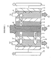
- numeral 1 represents a cathode, 2 and 2' anion-exchange membranes, 3 and 3' concentration compartments, 4 and 4' cation-exchange membranes, 5 a deionization compartment, 6 a non-woven fabric composed of cation-exchange fiber, 7 a non-woven fabric composed of anion-exchange fiber, 8 a deionization compartment spacer that is placed in the deionization compartment to provide the passageway of the feed water, 9 and 9' concentration compartment spacers that are placed in the concentration compartments to provide the passageways of the concentrate water, and 10 an anode.
- Numeral 11 represents the feed water, 12 the product water (deionized water), 13 and 13' effluent streams of water from the concentration compartments, and 14 and 14' the streams of concentration water being introduced into the concentration compartments.
- Fig. 1 shows schematically an electrical deionization apparatus according to an embodiment of the invention.
- the cathode 1 and the anode 10 at opposite ends have between them the following components in the order written: anion-exchange membrane 2, concentration compartment 3, cation-exchange membrane 4, non-woven fabric 6 made of cation-exchange fiber, deionization compartment 5, non-woven fabric 7 made of anion-exchange fiber, anion-exchange membrane 2', concentration compartment 3', and cation-exchange membrane 4'.
- the alternation of two sets of the cation-exchange membrane and anion-exchange membrane may be repeated in at least a part of the apparatus to provide a parallel array of two or more deionization compartment cells (pairs of one concentration compartment, deionization compartment and another concentration compartment).
- the ion-conducting spacer 8 is placed within the deionization compartment 5 to provide the passageway of the feed water.
- no electrode compartment is shown but, if desired, the concentration compartment that is the closest to an electrode may be used as an electrode compartment; alternatively, an independent electrode compartment may be provided adjacent the concentration compartment that is the closest to an electrode and in a position that is close enough to the electrode to contact it.
- concentration compartment that is the closest to an electrode is used as an electrode compartment, there is no need to provide an ion-exchange membrane on the side of said compartment closer to the electrode.
- the arrangement of ion-exchange membranes may be such that ion-exchange membranes of the same type succeed each other in at least a part of the apparatus.
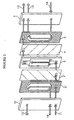
- Fig. 2 shows the structures of the members that make up the electrical deionization apparatus of the invention which is shown schematically in Fig. 1 .
- the apparatus shown in Fig. 2 has only one deionization compartment cell.
- the concentration compartment that is the closest to an electrode is used as an electrode compartment, there is no need to provide an ion-exchange membrane on the side of said compartment closer to the electrode; therefore, in the apparatus shown in Fig. 2 , the concentration compartment on either side has no ion-exchange membrane provided on the electrode side.
- the structure of the deionization compartment 5 is shown specifically in Fig.
- anions such as Cl - and SO 4 2- in the feed water undergo ion-exchange on the anion-exchange non-woven fabric 7 in the deionization compartment 5 and driven by the electric field to transfer the anion-exchange non-woven fabric 7 and the anion-exchange membrane 2' to permeate the concentration compartment 3', from which it is discharged as the stream of concentrate water 13'.
- the concentration compartment 3 or 3'
- the cations in the supplied stream of concentration water 9 (or 9') are attracted toward the cathode and the anions toward the anode; however, on account of the blocking ion-exchange membrane, they cannot permeate but remain as such in the concentrate water and are cleared in the concentrate water 13 (or 13').
- the electrical deionization apparatus of the invention as the feed water 11 is distributed to pass through the deionization compartment 5 while forming turbulent flows under the action of the diagonal net of spacer 8, the cations are trapped on the cation-exchange non-woven fabric 6 and the anions on the anion-exchange non-woven fabric 7. As a result, the ionic substances in the feed water 11 are removed with high efficiency to yield highly deionized product water 12.
- the deionization apparatus of the invention has also been found to have a surprising effect in that it can effectively remove the TOC that was difficult to remove not only by the conventional electrical deionization apparatus but also by the ion-exchange resin technology.
- One or more ion-conducting spacers 8 may be placed within the deionization compartment.
- a cation-conducting spacer and an anion-conducting spacer that have different ion-exchanging capabilities may be used in any suitable combinations.
- deionization apparatus of various performance levels can be fabricated.
- an anion-conducting spacer and a cation-conducting spacer may be placed adjacent the anion- and cation-exchange fibers, respectively, within the deionization compartment.
- another ion-conducting spacer is preferably placed in the concentration compartment 3. While either a cation-conducting spacer or an anion-conducting spacer may be applied, the former is preferred if one wants to suppress the elevation in the cation concentration on the surface of a cation-exchange membrane and the latter is preferred if one wants to suppress the elevation in the anion concentration on the surface of an anion-exchange membrane.
- another ion-conducting spacer is desirably placed in an electrode compartment in order to reduce its electrical resistance. It is generally preferred to place a cation-conducting spacer in the cathode compartment made up by the cation-exchange membrane and the cathode: particularly in the case where one wants to suppress the concentration of cations on the cathode surface, a cation-conducting spacer may be placed on the cation-exchange membrane side whereas an anion-conducting spacer or a polyolefinic spacer into which no ion-exchange groups have been introduced is placed on the cathode surface side and this is effective in suppressing the elevation in the ion concentrations on both the cation-exchange membrane surface and the cathode surface.
- an anion-conducting spacer in the anode compartment defined by the anion-exchange membrane and the anode; particularly in the case where one wants to suppress the concentration of anions on the anode surface, an anion-conducting spacer may be placed on the anion-exchange membrane side whereas a cation-conducting spacer or a polyolefinic spacer into which no ion-exchange groups have been introduced is placed on the anode surface side and this is effective in suppressing the elevation in the ion concentrations on both the anion-exchange membrane surface and the anode surface.
- Providing an ion-conducting spacer not only in the deionization compartment but also in the concentration compartments and the electrode compartments offers an advantage in that even if concentration water having a very low ion concentration is used, the areas where the ion-conducting spacer is present become as if they had an increased ion concentration and the electrical resistance is correspondingly lowered to permit more electric current to flow.
- the ion concentration in the concentration fluid is lowered, fewer ions diffuse from the concentration compartment to the deionization compartment and deionization proceeds at such a low voltage that the feed water can easily be deionized to an ion concentration close to the level for ultra-pure water.
- the electrical deionization apparatus of the invention operates on the principle that the water in the deionization compartment is dissociated to produce H + and OH - ions, which regenerate the ion exchanger in the deionization compartment to allow for continued ion exchange. If no ion-conducting spacer is used in the concentration compartment, the generated OH - ions, as they permeate the anion-exchange membrane, move faster in the membrane than in the water to become concentrated on the boundary layer on the side of the anion-exchange membrane which faces the concentration compartment; the concentrated OH - ions react with hardness components such as Ca and Mg in the concentrate water to form precipitates such as CaCO 3 and Mg(OH) 2 , making it difficult to continue the operation in a consistent manner.
- an anion-conducting spacer is provided in the concentration compartment of the electrical deionization apparatus of the invention as mentioned above, the mobility of anions within the concentration compartment increases to restrain the increase in the concentration of OH - ions on the boundary layer of the anion-exchange membrane, thereby permitting consistent operation to be performed with greater ease.
- concentration water If a fluid having low ion concentration equivalent to a specific resistance of 5 M ⁇ cm or more is supplied as the concentration water, precipitates are less prone to form since the concentration water inherently contains small amounts of hardness components such as Ca and Mg.
- deionized water having quality at least comparable to that of water treated by RO (reverse osmosis) to have a specific resistance of about 0.1 M ⁇ cm or more can consistently be produced from filtered water having ion concentrations at the levels for city water (with a specific resistance of about 0.005 M ⁇ cm or less), and high-purity water (having a specific resistance of about 15 M ⁇ cm or more) from water of the quality comparable to that of RO treated water, and ultra-pure water (having a specific resistance of about 18 M ⁇ cm or more) from the high-purity water.
- the apparatus consumes less power and, hence, can be constructed in a larger size.
- the non-woven fabrics and spacers are advantageously functionalized with ion-exchanging capabilities by grafting, preferably by radiation-induced graft polymerization.
- Radiation-induced graft polymerization is a technique by which a polymeric substrate is exposed to radiation to form radicals, which are reacted with a monomer so that it is introduced into the substrate.
- a polyolefinic polymer in particular, polyethylene is a common substrate for non-woven fabrics; a composite of polyethylene and polypropylene is particularly preferred but this is not the sole example that can be employed.
- Substrates for the spacer include polyolefinic polymers such as polyethylene and polypropylene.
- polyethylene is preferably used since it allows for easy radiation-induced graft polymerization.
- the ion-exchange groups to be introduced into the substrates for non-woven fabrics and spacer are not limited in any particular way and various cation- and anion-exchange groups may be employed.
- Exemplary cation exchangers include those which contain cation-exchange groups such as a sulfonic group, a carboxyl group, a phosphoric group and a phenolic hydroxyl group
- exemplary anion exchangers include those which contain anion-exchange groups such as primary, secondary and tertiary amino groups and a quaternary ammonium group.
- ion exchangers containing both a cation- and an anion-exchange group may be employed.
- Polymerizable monomers are grafted to the substrates for the non-woven fabrics and spacer to be used in the electrical deionization apparatus of the invention and they have either ion-exchange groups or groups that can be converted to ion-exchange groups.
- Monomers having ion-exchange groups may be exemplified by acrylic acid (AAc), methacrylic acid, sodium styrenesulfonate (SSS), sodium methallylsulfonate, sodium allylsulfonate and vinylbenzyltrimethyl ammonium chloride (VBTAC) and these may be subjected to radiation-induced graft polymerization to introduce ion-exchange groups directly into the substrates.
- Monomers having groups that can be converted to ion-exchange groups include acrylonitrile, acrolein, vinylpyridine, styrene, chloromethylstyrene and glycidyl methacrylate (GMA).
- GMA glycidyl methacrylate
- glycidyl methacrylate may be introduced into the substrate by radiation-induced graft polymerization, then reacted with a sulfonating agent such as sodium sulfite to introduce sulfonic groups or aminated with diethanolamine or the like to produce ion-exchange non-woven fabrics or ion-conducting spacer.
- At least a sulfonic group is preferably introduced and when introducing anion-exchange groups, at least a quaternary ammonium group is preferably introduced.
- the pH of the feed water is in the neutral range and unless the ion-exchange group available is either a sulfonic group or a quaternary ammonium group that can dissociate even in this pH range, the operating voltage becomes so high that the deionization apparatus of the invention may occasionally fail to exhibit the intended performance.
- a carboxyl group which is a weakly acidic cation-exchange group, a tertiary amino group which is a weakly basic anion-exchange group and lower amino groups may also be present in the non-woven fabrics and spacer; however, in the case of non-woven fabrics, each of a sulfonic group and a quaternary ammonium group is preferably present in an amount of 0.5 - 3.0 meq/g in terms of salt splitting capacity and, in the case of spacer, each of these groups is preferably present in an amount of 0.5 - 2.0 meq/g in terms of salt splitting capacity.
- the ion exchange capacity can be adjusted by varying the graft ratio and the higher the graft ratio, the larger the ion exchange capacity.
- the deionization compartment in the electrical deionization apparatus of the invention has preferably a thickness of 2.5 - 5 mm and considering the requirements for lower voltage and larger flow volume, a thickness of 3 - 4 mm is particularly preferred as proposed in Japanese Patent Public Disclosure No. 99221/1997 , supra.
- the present inventors conducted many experiments on the deionization compartment that was filled with various kinds of ion-exchange non-woven fabrics and ion-conducting spacers.
- the substrate for non-woven fabrics should preferably have a thickness of 0.1 - 1.0 mm, an areal density of 10 - 100 g/m 2 , a porosity of 50 - 98% and a fiber size of 10 - 70 ⁇ m whereas the substrate for spacer should preferably have a thickness of 0.3 - 1.5 mm.
- a diagonal net is a preferred shape of the spacer to be filled in the deionization compartment and preferably in the concentration compartment, too, of the electrical deionization apparatus of the invention.
- the spacer should satisfy many conditions, among which the following are particularly important: the feed water should easily produce turbulent flows that are distributed randomly as it flows; the spacer should have sufficiently intimate contact with the ion-exchange fiber; the dissolution of unwanted substances and the generation of particles should be minimal; the pressure loss should be small; and the spacer should be in sufficient contact with the non-woven fabrics to prevent them from becoming deformed or compacted.
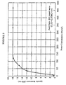
- An advantageous substrate that satisfies these conditions is a diagonal net of the type shown in Fig. 3 but this is not the sole example that can be employed.
- the thickness of the net is advantageously within the range of 0.3 - 1.5 mm since the flow volume of the feed water can be sufficiently increased to reduce the pressure loss. More than one spacer can be placed if the total thickness is within the stated range.
- the deionization compartment which preferably has a thickness of 2.5 - 5 mm is fitted with an assembly of the cation- and anion-exchange non-woven fabrics that are spaced apart by the ion-conducting spacer.
- the sum of the thicknesses of the respective members is greater than the thickness of the deionization compartment.
- the thickness of each member can be determined appropriately considering various factors such as flow volume, pressure loss, the quality of feed water and voltage.
- the same comment applies to the shape of the spacer to be loaded in the concentration compartment and the electrode compartment and the thickness of each member and these may be determined appropriately considering various factors such as flow volume, pressure loss and the dispersibility of the concentrate water.
- each of the deionization compartment and the concentration compartment including the electrode compartment is defined by a frame which is advantageously made of rigid poly(vinyl chloride), polyethylene or EPDM since these are easily available, can be processed easily and have good shape stability.
- a frame which is advantageously made of rigid poly(vinyl chloride), polyethylene or EPDM since these are easily available, can be processed easily and have good shape stability.
- composition of the deionization apparatus is typically shown in Fig. 1 ; one or more cells each consisting of a deionization compartment held between two concentration compartments are placed between electrodes at opposite ends, with each cell being composed of ion-exchange membranes, ion-exchange non-woven fabrics and an ion-conducting spacer.
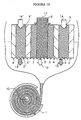
- Fig. 1 Another embodiment of the invention is shown in Fig.
- sheets of ion-exchange membranes, ion-exchange non-woven fabrics and ion-conducting spacer are placed one on another to form a composite sheet member that comprises a cell consisting of a deionization compartment held between two concentration compartments; the composite sheet member is then wound onto an electrode into a cylindrical form, which is surrounded with the other electrode to fabricate a deionization unit.
- a plurality of ion-exchange membranes may be arranged to alternate with each other, thereby forming a sheet member having a plurality of deionization compartment cells in a parallel array.
- cation-exchange membranes are alternated with anion-exchange membranes to form deionization compartments that alternate with concentration compartments, and a woven or non-woven fabric made of cation-exchange fiber is loaded in each deionization compartment such that it is placed on the cation-exchange membrane side in a face-to-face relationship with a woven or non-woven fabric made of anion-exchange fiber that is placed on the anion-exchange membrane side, and an ion-conducting spacer provided with an ion-exchanging capability is placed in the passageway of feed water between the two woven or non-woven fabrics to assemble a sheet member; the sheet member is then wound onto an electrode into a cylindrical form, which is surrounded with the electrode of other polarity, thereby completing the fabrication of an electrical deionization apparatus.
- Fig. 10 the components which are identical to those of the deionization apparatus shown in Fig. 1 are identified by like numerals, except
- Table 1 shows the specifications of the substrate non-woven fabric used in Example 1 to prepare an ion-exchange non-woven fabric.
- the substrate non-woven fabric was prepared by thermal fusion of composite fibers consisting of a polypropylene core and a polyethylene sheath.
- TABLE 1 Core/sheath Polypropylene/polyethylene Areal density 50 g/m 2 Thickness 0.55 mm Fiber diameter 15 - 40 ⁇ m Process Thermal fusion Porosity 91%
- Table 2 shows the specifications of the diagonal net used as the substrate for preparing an ion-conducting spacer in Example 1.
- TABLE 2 Constituent material Polyethylene Shape Diagonal net Thickness 0.8 mm Mesh opening 6 mm x 3 mm
- an electrical deionization apparatus of the construction shown in Fig. 1 was assembled.
- the commercial ion-exchange membranes were the cation- and anion-exchange membranes produced by Tokuyama Corp. and sold under the respective trade names, C66-10F and AMH.
- the assembled deionization apparatus had a parallel array of 11 deionization compartment cells of the structure shown in Fig. 1 .
- Each deionization compartment measured 400 x 600 mm with a thickness of 3 mm and each concentration compartment was 0.8 mm thick.
- Each deionization compartment was loaded with one sheet of the cation-conducting spacer (see above) on the cation-exchange non-woven fabric side and also one sheet of the anion-conducting spacer (see above) on the anion-exchange non-woven fabric side.
- No ion-conducting spacer was loaded within the concentration compartments; instead, they each were loaded with a single sheet of polyethylene diagonal net that had not been subjected to graft polymerization.
- a water pass test was conducted with the same apparatus as used in Example 1, except that the deionization compartments were filled with two spacers that were solely made of the substrate diagonal net (see Table 2) which was not subjected to graft polymerization and which hence had no ion conductivity.
- the quality of the product water was no better than 15 M ⁇ cm in terms of specific resistance but the voltage between cells increased to 720 V.
- the ion-exchange membranes, ion-exchange non-woven fabrics and ion-conducting spacers that were of the same types as used in Example 1 were arranged in the same manner to assemble a deionization apparatus of the construction shown in Fig. 1 . Eleven deionization compartment cells were formed. Using this deionization apparatus, a water pass test was conducted under the conditions shown in Table 4. The feed water was tap water that was freed of organic matter and iron by the combination of adsorption on activated charcoal, microfiltration (MF) and treatment with a nano-filter (NF). The product water had specific resistances of 3 - 3.5 M ⁇ cm. TABLE 4 Feed water Electroconductivity Filtered water of feed water 160 - 230 ⁇ S/cm Water temperature 12 - 18°C Flow volume 0.5 m 3 /h
- ion-exchange non-woven fabrics ion-conducting spacers and ion-exchange membranes that were of the same types as used in Example 1
- the deionization compartments each measured 400 x 600 mm with a thickness of 3 mm.
- the concentration compartments each had a thickness of 1.5 mm.
- the assembled deionization apparatus had a parallel array of 11 deionization compartment cells of the configuration shown in Fig. 1 .
- Each deionization compartment was loaded with one sheet of cation-conducting spacer on the cation-exchange non-woven fabric side and one sheet of anion-conducting spacer on the anion-exchange non-woven fabric side.
- Each concentration compartment was loaded with one sheet of 0.8 mm thick anion-conducting spacer on the anion-exchange membrane side and one sheet of 0.8 mm thick cation-conducting spacer on the cation-exchange membrane side.
- Feed water was passed through this apparatus as in Example 1 under the conditions shown in Table 3.
- the product water had consistent values of specific resistance and TOC at 17.2 M ⁇ cm and 28 - 35 ppb, respectively.
- the operating voltage was 240 V and the pressure loss was no greater than 0.3 kg/cm 2 .
- the silica removal was also as high as 96%.
- the specific resistance of the product water could be controlled by controlling the voltage and current being applied.
- An 11-cell deionization unit was assembled as in Example 3, except that the outermost concentration compartments (on the electrode side) which served as anode and cathode compartments were loaded with a cation-conducting spacer (in the cathode compartment) and an anion-conducting spacer (in the anode compartment). Two such units were connected in series to build a deionization apparatus.
- the cathode compartments of 1.5 mm thick were each loaded with two sheets of cation-conducting spacer 0.8 mm thick and the anode compartments of 1.5 mm thick were each loaded with two sheets of anion-conducting spacer 0.8 mm thick.
- the product water exiting in a flow volume of 1.33 m 3 /h from the deionization compartment 5 in the first-stage unit of the deionization apparatus was branched in a volume of 0.33 m 3 /h and supplied into the concentration compartment 3 in the second-stage unit, the product water exiting from the concentration compartment 3 in the second-stage unit was supplied into the concentration compartment 3 in the first-stage unit, and the product water 13 exiting from the concentration compartment 3 in the first-stage unit was recovered into the supply tank to the RO apparatus.
- Example 1 A water pass test was conducted as in Example 1 under the conditions set forth in Table 3 to give the performance curve shown in Fig. 5 which described the quality of the product water 12 from the deionization compartment in the second-stage unit as a function of the total power consumed by the two units.
- the product water 12 had a consistent TOC level at 10 ppb or less.
- the pressure loss through the two units was no more than 0.6 kg/cm 2 .
- the silica removal was 99% or more for the total power consumption of 0.6 kWh/m 3 .
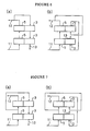
- Figs. 6 - 9 are flow diagrams showing how the streams of deionization water and concentration water are supplied to the respective units in a two-stage configuration of the deionization apparatus.
- Each diagram labeled (a) refers to a counter-current system and each labeled (b) refers to a concurrent system.
- the lower block designates the first-stage unit of deionization apparatus and the upper block the second-stage unit; numeral 5 refers to the deionization compartment; 3 is the concentration compartment; 11 is the feed water to the deionization compartment in the first-stage unit; 12 is the (deionized) product water exiting from the deionization compartment in the second-stage unit; 13 is the concentrate water being recirculated to the supply tank of the feed water.
- two units of the deionization apparatus of the invention may be series-connected in various circuits to implement the invention.
- a diagonal net substrate (see Table 2) of the same type as used in Example 1 was irradiated with ⁇ -rays in a nitrogen atmosphere and thereafter immersed in a liquid mixture of sodium styrenesulfonate (SSS), acrylic acid (AAc) and water for reaction, and graft ratio of 160% was obtained.
- SSS sodium styrenesulfonate
- AAc acrylic acid
- water water for reaction
- graft ratio of 160% was obtained.
- Measurement of ion-exchange conductivity revealed the production of a strong acidic cation-conducting spacer having a salt splitting capacity of 1.05 meq/g.
- Another sample of the same diagonal net substrate was irradiated with ⁇ -rays in a nitrogen atmosphere and immersed in a liquid mixture of vinylbenzyltrimethyl ammonium chloride (VBTAC), DMAA and water for reaction, and a graft ratio of 130% was obtained.
- the product was a strong basic anion-conducting spacer having a salt splitting capacity of 0.82 meq/g.
- Example 4 an electrical deionization apparatus of the construction shown in Fig. 1 was assembled as in Example 4.
- the ion-exchange membranes were of the same types as used in Example 1. It consisted of two series-connected units each having 11 deionization compartment cells of the construction shown in Fig. 1 . Each deionization compartment measured 400 x 600 mm with a thickness of 3 mm, and each concentration compartment had a thickness of 1.5 mm. Each deionization compartment was loaded with two sheets of the cation-conducting spacer (see above). Each concentration compartment was loaded with a 0.8 mm thick sheet of anion-conducting spacer on the anion-exchange membrane side and a 0.8 mm thick sheet of cation-conducting spacer on the cation-exchange membrane side.
- Feed water was passed through this apparatus as in Example 4 under the conditions set forth in Table 3.
- the total power consumed by the two units was 0.15 kWh/m 3 and the product water had consistent values of specific resistance and TOC at 17 M ⁇ cm and 30 ppb or less, respectively.
- the pressure loss was as low as 0.6 kg/cm 2 or less.
- the silica removal was also satisfactory at 90%.
- the specific resistance of the product water could be controlled by adjusting the voltage and current being applied.
- Example 5 Using the ion-exchange non-woven fabrics and the ion-conducting spacers in Example 5, an electrical deionization apparatus of the construction shown in Fig. 1 was assembled.
- the ion-exchange membranes were of the same types as used in Example 1. It consisted of two series-connected units each having 11 deionization compartment cells of the construction shown in Fig. 1 . Each deionization compartment measured 400 x 600 mm with a thickness of 3 mm, and each concentration compartment had a thickness of 1.5 mm.
- Each deionization compartment was loaded with two sheets of the anion-conducting spacer (see above). Each concentration compartment was loaded with a 0.8 mm thick sheet of anion-conducting spacer on the anion-exchange membrane side and a 0.8 mm thick sheet of cation-conducting spacer on the cation-exchange membrane side.
- Feed water was passed through this apparatus as in Example 4 under the conditions set forth in Table 3.
- the total power consumed by the two units was 0.3 kWh/m 3 and the product water had consistent values of specific resistance and TOC at 18.1 M ⁇ cm and 5 ppb or less, respectively.
- the pressure loss was as low as 0.6 kg/cm 2 or less.
- the silica removal was also satisfactory at 99.5%.
- the specific resistance of the product water could be controlled by adjusting the voltage and current being applied.
- the deionization compartment of an electrical deionization apparatus is loaded with not only ion-exchange non-woven fabrics but also spacers provided with an ion-conducting capabilities.
- the apparatus of the invention is markedly improved in the quality of product water and reduced in power consumption and deionization can be performed in a higher efficiency, with smaller dissolution of unwanted matter, at a lower running cost and requiring a smaller installation space.
- the electrical deionization apparatus of the invention even ultra-pure water can be produced without chemicals but using only electrical energy.
- ion-conducting spacers are also loaded in the concentration compartment and this contributes to make a further improvement in performance.
- Another advantage of the electrical deionization apparatus of the invention is that product water of the desired quality can be obtained by merely changing the treatment conditions (electrical conditions).
Landscapes
- Chemical & Material Sciences (AREA)
- Chemical Kinetics & Catalysis (AREA)
- Engineering & Computer Science (AREA)
- Water Supply & Treatment (AREA)
- Organic Chemistry (AREA)
- Health & Medical Sciences (AREA)
- Life Sciences & Earth Sciences (AREA)
- Analytical Chemistry (AREA)
- General Chemical & Material Sciences (AREA)
- Hydrology & Water Resources (AREA)
- Electrochemistry (AREA)
- Environmental & Geological Engineering (AREA)
- Molecular Biology (AREA)
- Urology & Nephrology (AREA)
- Separation Using Semi-Permeable Membranes (AREA)
- Water Treatment By Electricity Or Magnetism (AREA)
- Electrical Discharge Machining, Electrochemical Machining, And Combined Machining (AREA)
- Treatment Of Water By Ion Exchange (AREA)
- Control Of Electric Motors In General (AREA)
- Developing Agents For Electrophotography (AREA)
- Fats And Perfumes (AREA)
Claims (17)
- Elektrische Deionisierungsvorrichtung, bei der zumindest ein Teil der Kationenaustauschmembranen (4, 4') und der Anionenaustauschmembranen (2, 2') zwischen Elektroden (1, 10) abwechseln, um eine abwechselnde Anordnung von Deionisierungs- und Konzentrationsabteilen (5; 3, 3') zu bilden, und wobei das Deionisierungsabteil (5) einen gewebten oder nicht gewebten Stoff aus einer Kationenaustauschfaser enthält, der auf der Kationenaustauschmembranseite in einer Stirnseite an Stirnseite liegender Beziehung mit einem gewebten oder nicht gewebten Stoff angeordnet ist, der aus einer Anionenaustauschfaser gemacht ist, der auf der Anionenaustauschmembranseite angeordnet ist, wobei der Durchlassweg für Einspeisungswassers zwischen den zwei gewebten oder nicht gewebten Stoffen einen Ionen leitenden Abstandshalter (8) aufweist, der mit einer lonenaustauschfähigkeit versehen ist.
- Elektrische Deionisierungsvorrichtung nach Anspruch 1, wobei zumindest ein Teil der Kationenaustauschmembranen und der Anionenaustauschmembranen, der gewebten oder nicht gewebten Stoffen und der lonenaustauschabstandshalter (8) zu einem Flächenelementglied montiert sind, welches dann auf eine Elektrode zu einer zylindrischen Form gewickelt ist und mit der Elektrode der anderen Polarität umgeben ist.
- Elektrische Deionisierungsvorrichtung nach Anspruch 1 oder 2, wobei der Durchlassweg für Einspeisungswasser in das Deionisierungsabteil (5) mit einem Kationen leitenden Abstandshalter auf der Kationenaustauschseite des nicht gewebten Stoffes und einem Anionen leitenden Abstandshalter auf der Anionenaustauschseite des nicht gewebten Stoffes belastet bzw. beschlagen ist.
- Elektrische Deionisierungsvorrichtung nach Anspruch 1 oder 2, wobei der Durchlassweg für Einspeisungswasser (11) in dem Deionisierungsabteil (5) mit einem oder mehreren Kationen leitenden Abstandshaltern beladen bzw. beschlagen ist.
- Elektrische Deionisierungsvorrichtung nach Anspruch 1 oder 2 , wobei der Durchlassweg für Einspeisungswasser (11) in dem Deionisierungsabteil (5) mit einem oder mehreren Anionen leitenden Abstandshaltern beladen bzw. beschlagen ist.
- Elektrische Deionisierungsvorrichtung nach einem der Ansprüche 1-5, wobei der Durchlassweg für konzentriertes Wasser in dem Konzentrationsabteil (3; 3') mit einem Ionen leitenden Abstandshalter beladen bzw. beschlagen ist, der mit einer Ionenaustauschfähigkeit versehen ist.
- Elektrische Deionisierungsvorrichtung nach Anspruch 6, wobei der Durchlassweg für konzentriertes Wasser in dem Konzentrationsabteil (3; 3') mit einem Kationen leitenden Abstandshalter auf der Seite der Kationenaustauschmembran (4, 4') und einem Anionen leitenden Abstandshalter auf der Seite der Anionenaustauschmembran (2, 2') beladen bzw. beschlagen ist.
- Elektrische Deionisierungsvorrichtung nach einem der Ansprüche 1-7, wobei ein Elektrodenabteil zwischen jeder Elektrode und der Ionenaustauschmembran benachbart zur Elektrode ausgeformt ist.
- Elektrische Deionisierungsvorrichtung nach einem der Ansprüche 1-7, wobei das Konzentrationsabteil (3, 3') benachbart zu jeder Elektrode ein Elektrodenabteil definiert.
- Elektrische Deionisierungsvorrichtung nach Anspruch 8 oder 9, wobei zumindest ein Teil des Durchlassweges des Wassers, welches durch das Elektrodenabteil fließt, mit einem Ionen leitenden Abstandshalter beladen bzw. beschlagen ist, der mit einer Ionenaustauschfähigkeit versehen ist.
- Elektrische Deionisierungsvorrichtung nach Anspruch 10, wobei zumindest ein Teil des Durchlassweges des Wassers, welches durch das Anodenabteil fließt, mit einem Anionen leitenden Abstandshalter beladen bzw. beschlagen ist, und wobei zumindest ein Teil des Durchlassweges des Wassers, welches durch das Kathodenabteil fließt, mit einem Kationen leitenden Abstandshalter beladen bzw. beschlagen ist.
- Elektrische Deionisierungsvorrichtung nach einem der Ansprüche 1-11, wobei der gewebte Stoff oder der nicht gewebte Stoff aus Ionenaustauschfaser ein Substrat aufweist, welches aus Polyolefinfasern mit hohem Molekulargewicht gemacht ist, in welche Ionenaustauschgruppen durch durch Strahlung eingeleitete Pfropfpolymerisation eingeleitet worden sind.
- Elektrische Deionisierungsvorrichtung nach einem der Ansprüche 1-12, wobei der Ionen leitenden Abstandshalter ein diagonales Netzsubstrat aufweist, welches aus Polyolefinfasern mit hohem Molekulargewicht gemacht ist, in die Ionenaustauschgruppen durch durch Strahlung eingeleitete Pfropfpolymerisation eingeführt worden sind.
- Elektrische Deionisierungsvorrichtung nach Anspruch 12, wobei der gewebte Stoff oder der nicht gewebte Stoff, der aus einer Ionenaustauschfaser hergestellt ist, auf einem Faserverbundsubstrat basiert, welches eine Po-Iypropylenkernkomponente und eine Polyethylenhüllenkomponente aufweist, und in welches Schwefelgruppen oder Gruppen aus quaternärem Ammoniak durch durch Strahlung hervorgerufene Pfropfpolymerisation eingeführt worden sind.
- Elektrische Deionisierungsvorrichtung nach Anspruch 13, wobei der Ionen leitenden Abstandshalter ein diagonales Polyethylen-Netzsubstrat aufweist, in welches Schwefelgruppen oder Gruppen aus quaternärem Ammonium durch durch Strahlung eingeleitete Pfropfpolymerisation eingeführt worden sind.
- Elektrische Deionisierungsvorrichtung nach einem der Ansprüche 1-15, wobei das Deinonisierungsabteil (5) und das Konzentrationsabteil (3, 3') beide aus einem Rahmenglied aufgebaut sind, welches Leitungen hat, die das Hindurchleiten von Einspeisungswasser, Produktwasser und Konzentratwasser gestatten, wobei eine Vielzahl von solchen Deionisierungs- und Konzentrationsabteilen stapelartig angeordnet ist, um die Deionisierungsvorrichtung zusammenzustellen.
- Elektrische Deionisierungsvorrichtung nach einem der Ansprüche 1-16, wobei das Konzentrationsabteil (3, 3') mit deinonisiertem Wasser beliefert wird, welches einen spezifischen Widerstand von mindestens 5MΩ.· cm hat.
Applications Claiming Priority (5)
| Application Number | Priority Date | Filing Date | Title |
|---|---|---|---|
| JP9386898 | 1998-03-24 | ||
| JP9386898 | 1998-03-24 | ||
| JP15369798 | 1998-05-20 | ||
| JP15369798 | 1998-05-20 | ||
| PCT/JP1999/001391 WO1999048820A1 (en) | 1998-03-24 | 1999-03-19 | Electric desalting apparatus |
Publications (3)
| Publication Number | Publication Date |
|---|---|
| EP1069079A1 EP1069079A1 (de) | 2001-01-17 |
| EP1069079A4 EP1069079A4 (de) | 2006-05-10 |
| EP1069079B1 true EP1069079B1 (de) | 2008-11-05 |
Family
ID=26435150
Family Applications (1)
| Application Number | Title | Priority Date | Filing Date |
|---|---|---|---|
| EP99910671A Expired - Lifetime EP1069079B1 (de) | 1998-03-24 | 1999-03-19 | Elektrische entionisierungsvorrichtung |
Country Status (8)
| Country | Link |
|---|---|
| US (1) | US6423205B1 (de) |
| EP (1) | EP1069079B1 (de) |
| JP (1) | JP4065664B2 (de) |
| CN (1) | CN1136155C (de) |
| AT (1) | ATE413365T1 (de) |
| CA (1) | CA2325403C (de) |
| DE (1) | DE69939865D1 (de) |
| WO (1) | WO1999048820A1 (de) |
Families Citing this family (31)
| Publication number | Priority date | Publication date | Assignee | Title |
|---|---|---|---|---|
| JP3385553B2 (ja) | 1999-03-25 | 2003-03-10 | オルガノ株式会社 | 電気式脱イオン水製造装置及び脱イオン水製造方法 |
| JP4343105B2 (ja) * | 2002-05-17 | 2009-10-14 | 株式会社荏原製作所 | 電気式脱塩装置 |
| FR2845082B1 (fr) | 2002-09-26 | 2006-02-10 | Millipore Corp | Module de purification d'un fluide, notamment d'eau |
| CA2413467A1 (en) * | 2002-11-29 | 2004-05-29 | Ian Glenn Towe | Spacer for electrically driven membrane process apparatus |
| JP4454502B2 (ja) | 2002-12-27 | 2010-04-21 | 荏原エンジニアリングサービス株式会社 | 電気式脱塩装置 |
| EP1651331B1 (de) * | 2003-08-05 | 2007-05-30 | Millipore Corporation | Modul zur elektrischen entionisierung und dieses umfassende vorrichtung |
| GB0406141D0 (en) * | 2004-03-18 | 2004-04-21 | Boc Group Plc | Electromembrane process and apparatus |
| CN100518905C (zh) * | 2004-11-02 | 2009-07-29 | 浙江欧美环境工程有限公司 | 折返式电除盐器 |
| NL1036698C2 (en) * | 2009-03-11 | 2010-09-14 | Stichting Wetsus Ct Excellence Sustainable Water Technology | Spacer, cell and device for an ion-exchanging process and method therefore. |
| EA026762B1 (ru) * | 2009-08-24 | 2017-05-31 | Оасис Уотер, Инк. | Прямоосмотическая мембрана |
| ES2748340T3 (es) | 2009-08-26 | 2020-03-16 | Evoqua Water Tech Pte Ltd | Membranas de intercambio iónico |
| WO2011069050A1 (en) | 2009-12-03 | 2011-06-09 | Yale University | High flux thin-film composite forward osmosis and pressure-retarded osmosis membranes |
| KR20130101533A (ko) | 2010-10-04 | 2013-09-13 | 오아시스 워터, 인크. | 박막 필름 복합 열 교환기 |
| SG189894A1 (en) | 2010-10-15 | 2013-06-28 | Siemens Industry Inc | Process for making a monomer solution for making cation exchange membranes |
| JP2013545595A (ja) | 2010-10-15 | 2013-12-26 | シーメンス インダストリー インコーポレイテッド | アニオン交換膜及び製造方法 |
| US8524062B2 (en) * | 2010-12-29 | 2013-09-03 | General Electric Company | Electrodeionization device and method with improved scaling resistance |
| CN103058425B (zh) | 2011-10-21 | 2015-07-29 | 通用电气公司 | 脱盐系统和方法 |
| EP2888205B1 (de) | 2012-08-27 | 2018-10-24 | Merck Patent GmbH | Verbessert elektrodeionisationsmodul und gerät |
| US20150315042A1 (en) | 2012-10-04 | 2015-11-05 | Evoqua Water Technologies Llc | High-Performance Anion Exchange Membranes and Methods of Making Same |
| US9540261B2 (en) | 2012-10-11 | 2017-01-10 | Evoqua Water Technologies Llc | Coated ion exchange membranes |
| KR102093443B1 (ko) * | 2012-11-29 | 2020-03-25 | 삼성전자주식회사 | 전기 흡착 탈이온 장치 및 이를 사용한 유체 처리 방법 |
| ITPD20130065A1 (it) | 2013-03-15 | 2014-09-16 | Idropan Dell Orto Depuratori S R L | Apparecchiatura per la purificazione di un fluido e metodo di purificazione di un fluido, in particolare mediante la suddetta apparecchiatura |
| KR20150094254A (ko) | 2014-02-11 | 2015-08-19 | 삼성전자주식회사 | 연수 장치 |
| KR101721697B1 (ko) * | 2016-01-18 | 2017-03-30 | 한남대학교 산학협력단 | 축전식 탈염장치 내의 유로형태 설계 |
| KR101833047B1 (ko) * | 2016-05-17 | 2018-02-27 | 한남대학교 산학협력단 | 축전식 탈염 장치 |
| CN112752789A (zh) | 2018-09-25 | 2021-05-04 | 懿华水处理技术有限责任公司 | 通过uv引发的聚合的离子交换膜 |
| KR20210070359A (ko) * | 2018-10-09 | 2021-06-14 | 에보쿠아 워터 테크놀로지스 엘엘씨 | 고 회수 전기투석 방법 |
| CN109898322A (zh) * | 2019-03-15 | 2019-06-18 | 天津工业大学 | 一种磺化非织造布及制备方法 |
| JP2022060806A (ja) * | 2020-10-05 | 2022-04-15 | オルガノ株式会社 | 純水製造システムおよび純水製造方法 |
| CN115028242B (zh) * | 2021-06-17 | 2024-07-02 | 上海安江环保科技合伙企业(有限合伙) | 一种实现粒子约束的电化学组件、装置及方法 |
| CN114084941A (zh) * | 2021-11-30 | 2022-02-25 | 中科精仪吉林省科技有限公司 | 基于双极性离子膜用的渗透析净水设备及其净水方法 |
Family Cites Families (17)
| Publication number | Priority date | Publication date | Assignee | Title |
|---|---|---|---|---|
| US2815320A (en) | 1953-10-23 | 1957-12-03 | Kollsman Paul | Method of and apparatus for treating ionic fluids by dialysis |
| US4925541B1 (en) | 1984-07-09 | 1994-08-02 | Millipore Corp | Electrodeionization apparatus and method |
| DE3568946D1 (en) | 1984-07-09 | 1989-04-27 | Millipore Corp | Improved electrodeionization apparatus and method |
| JPH0472567A (ja) | 1990-07-13 | 1992-03-06 | Canon Inc | 免疫的に活性な物質の測定方法および測定装置 |
| JP2865389B2 (ja) | 1990-07-10 | 1999-03-08 | オルガノ株式会社 | 電気式脱イオン水製造装置とそれに用いる枠体 |
| JP3200458B2 (ja) | 1991-03-13 | 2001-08-20 | 日本原子力研究所 | 電気再生式脱塩装置 |
| EP0503651B1 (de) | 1991-03-13 | 1995-08-23 | Ebara Corporation | Elektrisch regenerierbare Entmineralisierungsvorrichtung |
| JP3188511B2 (ja) | 1992-03-30 | 2001-07-16 | 野村マイクロ・サイエンス株式会社 | 電気透析装置 |
| ES2092267T3 (es) * | 1992-05-15 | 1996-11-16 | Christ Ag | Dispositivo para la desalinizacion electroquimica continua de soluciones acuosas. |
| JP3232466B2 (ja) | 1992-09-03 | 2001-11-26 | 東レ株式会社 | 超純水製造方法 |
| JP2751090B2 (ja) | 1993-04-21 | 1998-05-18 | 日本錬水株式会社 | 純水製造装置 |
| JP2699256B2 (ja) | 1993-10-05 | 1998-01-19 | 株式会社荏原製作所 | 電気再生式連続イオン交換装置とその使用方法 |
| AU7933094A (en) * | 1993-10-25 | 1995-05-22 | Bwt Aktiengesellschaft | Process for preparing salt-containing solutions |
| JPH08155272A (ja) * | 1994-11-30 | 1996-06-18 | Asahi Glass Co Ltd | 純水製造装置 |
| JP3513955B2 (ja) | 1995-01-19 | 2004-03-31 | 旭硝子株式会社 | 電気透析型脱イオン水製造方法 |
| JP3394372B2 (ja) | 1995-10-04 | 2003-04-07 | 株式会社荏原製作所 | 電気再生式脱塩装置 |
| IL120634A (en) * | 1997-04-10 | 2001-04-30 | Univ Ben Gurion | Interval replaces ions and processes for its preparation for electrode dialysis |
-
1999
- 1999-03-19 WO PCT/JP1999/001391 patent/WO1999048820A1/ja not_active Ceased
- 1999-03-19 EP EP99910671A patent/EP1069079B1/de not_active Expired - Lifetime
- 1999-03-19 JP JP2000537810A patent/JP4065664B2/ja not_active Expired - Lifetime
- 1999-03-19 CA CA002325403A patent/CA2325403C/en not_active Expired - Lifetime
- 1999-03-19 DE DE69939865T patent/DE69939865D1/de not_active Expired - Lifetime
- 1999-03-19 US US09/646,958 patent/US6423205B1/en not_active Expired - Lifetime
- 1999-03-19 AT AT99910671T patent/ATE413365T1/de not_active IP Right Cessation
- 1999-03-19 CN CNB998043176A patent/CN1136155C/zh not_active Expired - Lifetime
Also Published As
| Publication number | Publication date |
|---|---|
| WO1999048820A1 (en) | 1999-09-30 |
| JP4065664B2 (ja) | 2008-03-26 |
| DE69939865D1 (de) | 2008-12-18 |
| CA2325403C (en) | 2009-09-29 |
| EP1069079A4 (de) | 2006-05-10 |
| US6423205B1 (en) | 2002-07-23 |
| ATE413365T1 (de) | 2008-11-15 |
| CN1136155C (zh) | 2004-01-28 |
| EP1069079A1 (de) | 2001-01-17 |
| CA2325403A1 (en) | 1999-09-30 |
| CN1294564A (zh) | 2001-05-09 |
Similar Documents
| Publication | Publication Date | Title |
|---|---|---|
| EP1069079B1 (de) | Elektrische entionisierungsvorrichtung | |
| US5154809A (en) | Process for purifying water | |
| JP4778664B2 (ja) | 電気透析用の装置および方法 | |
| JPWO1999048820A1 (ja) | 電気式脱塩装置 | |
| EP1017482B1 (de) | Elektrochemisch unterstützter ionenaustausch | |
| JP3781361B2 (ja) | 電気式脱イオン水製造装置 | |
| CN101195081B (zh) | 防止电去离子作用装置中结垢的方法及装置 | |
| USRE35741E (en) | Process for purifying water | |
| EP1506941A1 (de) | Elektrischer entsalzer | |
| EP1577268B1 (de) | Elektrischer entsalzer | |
| US3761386A (en) | Novel membrane spacer | |
| JP2002527238A5 (de) | ||
| JP2003334560A (ja) | 電気式脱イオン水製造装置 | |
| US9550687B2 (en) | Electrodeionization module and apparatus | |
| JP4303242B2 (ja) | 電気式脱塩モジュール及び該モジュールを備えた装置 | |
| JP2003145164A (ja) | 電気式脱イオン水製造装置及び脱イオン水の製造方法 | |
| EP1462172A1 (de) | Elektrische entmineralisierungsvorrichtung | |
| JP4193586B2 (ja) | 電気再生式純水製造装置 | |
| JP2003190961A (ja) | 電気式脱塩装置 | |
| JP2004344847A (ja) | 電気再生式純水製造装置 | |
| IL302180A (en) | Electroionization configuration for accelerated removal of weakly ionized species | |
| JP2003190962A (ja) | イオン交換体及び電気式脱塩装置 | |
| JP2004105868A (ja) | 電気再生式純水製造装置 |
Legal Events
| Date | Code | Title | Description |
|---|---|---|---|
| PUAI | Public reference made under article 153(3) epc to a published international application that has entered the european phase |
Free format text: ORIGINAL CODE: 0009012 |
|
| 17P | Request for examination filed |
Effective date: 20000925 |
|
| AK | Designated contracting states |
Kind code of ref document: A1 Designated state(s): AT BE CH CY DE DK ES FI FR GB GR IE IT LI LU MC NL PT SE |
|
| A4 | Supplementary search report drawn up and despatched |
Effective date: 20060323 |
|
| RIC1 | Information provided on ipc code assigned before grant |
Ipc: B01D 61/48 20060101ALI20060317BHEP Ipc: C02F 1/469 20060101AFI19991012BHEP |
|
| 17Q | First examination report despatched |
Effective date: 20070209 |
|
| GRAP | Despatch of communication of intention to grant a patent |
Free format text: ORIGINAL CODE: EPIDOSNIGR1 |
|
| RTI1 | Title (correction) |
Free format text: ELECTRIC DEIONIZATION APPARATUS |
|
| GRAS | Grant fee paid |
Free format text: ORIGINAL CODE: EPIDOSNIGR3 |
|
| GRAA | (expected) grant |
Free format text: ORIGINAL CODE: 0009210 |
|
| AK | Designated contracting states |
Kind code of ref document: B1 Designated state(s): AT BE CH CY DE DK ES FI FR GB GR IE IT LI LU MC NL PT SE |
|
| REG | Reference to a national code |
Ref country code: GB Ref legal event code: FG4D |
|
| REG | Reference to a national code |
Ref country code: CH Ref legal event code: EP |
|
| REG | Reference to a national code |
Ref country code: IE Ref legal event code: FG4D |
|
| REF | Corresponds to: |
Ref document number: 69939865 Country of ref document: DE Date of ref document: 20081218 Kind code of ref document: P |
|
| NLV1 | Nl: lapsed or annulled due to failure to fulfill the requirements of art. 29p and 29m of the patents act | ||
| PG25 | Lapsed in a contracting state [announced via postgrant information from national office to epo] |
Ref country code: ES Free format text: LAPSE BECAUSE OF FAILURE TO SUBMIT A TRANSLATION OF THE DESCRIPTION OR TO PAY THE FEE WITHIN THE PRESCRIBED TIME-LIMIT Effective date: 20090216 Ref country code: AT Free format text: LAPSE BECAUSE OF FAILURE TO SUBMIT A TRANSLATION OF THE DESCRIPTION OR TO PAY THE FEE WITHIN THE PRESCRIBED TIME-LIMIT Effective date: 20081105 |
|
| PG25 | Lapsed in a contracting state [announced via postgrant information from national office to epo] |
Ref country code: NL Free format text: LAPSE BECAUSE OF FAILURE TO SUBMIT A TRANSLATION OF THE DESCRIPTION OR TO PAY THE FEE WITHIN THE PRESCRIBED TIME-LIMIT Effective date: 20081105 Ref country code: FI Free format text: LAPSE BECAUSE OF FAILURE TO SUBMIT A TRANSLATION OF THE DESCRIPTION OR TO PAY THE FEE WITHIN THE PRESCRIBED TIME-LIMIT Effective date: 20081105 |
|
| PG25 | Lapsed in a contracting state [announced via postgrant information from national office to epo] |
Ref country code: DK Free format text: LAPSE BECAUSE OF FAILURE TO SUBMIT A TRANSLATION OF THE DESCRIPTION OR TO PAY THE FEE WITHIN THE PRESCRIBED TIME-LIMIT Effective date: 20081105 Ref country code: BE Free format text: LAPSE BECAUSE OF FAILURE TO SUBMIT A TRANSLATION OF THE DESCRIPTION OR TO PAY THE FEE WITHIN THE PRESCRIBED TIME-LIMIT Effective date: 20081105 |
|
| PG25 | Lapsed in a contracting state [announced via postgrant information from national office to epo] |
Ref country code: SE Free format text: LAPSE BECAUSE OF FAILURE TO SUBMIT A TRANSLATION OF THE DESCRIPTION OR TO PAY THE FEE WITHIN THE PRESCRIBED TIME-LIMIT Effective date: 20090205 Ref country code: PT Free format text: LAPSE BECAUSE OF FAILURE TO SUBMIT A TRANSLATION OF THE DESCRIPTION OR TO PAY THE FEE WITHIN THE PRESCRIBED TIME-LIMIT Effective date: 20090406 |
|
| PLBE | No opposition filed within time limit |
Free format text: ORIGINAL CODE: 0009261 |
|
| STAA | Information on the status of an ep patent application or granted ep patent |
Free format text: STATUS: NO OPPOSITION FILED WITHIN TIME LIMIT |
|
| 26N | No opposition filed |
Effective date: 20090806 |
|
| PG25 | Lapsed in a contracting state [announced via postgrant information from national office to epo] |
Ref country code: MC Free format text: LAPSE BECAUSE OF NON-PAYMENT OF DUE FEES Effective date: 20090331 |
|
| REG | Reference to a national code |
Ref country code: CH Ref legal event code: PL |
|
| REG | Reference to a national code |
Ref country code: IE Ref legal event code: MM4A |
|
| PG25 | Lapsed in a contracting state [announced via postgrant information from national office to epo] |
Ref country code: LI Free format text: LAPSE BECAUSE OF NON-PAYMENT OF DUE FEES Effective date: 20090331 Ref country code: IE Free format text: LAPSE BECAUSE OF NON-PAYMENT OF DUE FEES Effective date: 20090319 Ref country code: CH Free format text: LAPSE BECAUSE OF NON-PAYMENT OF DUE FEES Effective date: 20090331 |
|
| REG | Reference to a national code |
Ref country code: GB Ref legal event code: 732E Free format text: REGISTERED BETWEEN 20100617 AND 20100623 |
|
| REG | Reference to a national code |
Ref country code: FR Ref legal event code: TP |
|
| PG25 | Lapsed in a contracting state [announced via postgrant information from national office to epo] |
Ref country code: GR Free format text: LAPSE BECAUSE OF FAILURE TO SUBMIT A TRANSLATION OF THE DESCRIPTION OR TO PAY THE FEE WITHIN THE PRESCRIBED TIME-LIMIT Effective date: 20090206 |
|
| PG25 | Lapsed in a contracting state [announced via postgrant information from national office to epo] |
Ref country code: IT Free format text: LAPSE BECAUSE OF FAILURE TO SUBMIT A TRANSLATION OF THE DESCRIPTION OR TO PAY THE FEE WITHIN THE PRESCRIBED TIME-LIMIT Effective date: 20081105 |
|
| PG25 | Lapsed in a contracting state [announced via postgrant information from national office to epo] |
Ref country code: LU Free format text: LAPSE BECAUSE OF NON-PAYMENT OF DUE FEES Effective date: 20090319 |
|
| PG25 | Lapsed in a contracting state [announced via postgrant information from national office to epo] |
Ref country code: CY Free format text: LAPSE BECAUSE OF FAILURE TO SUBMIT A TRANSLATION OF THE DESCRIPTION OR TO PAY THE FEE WITHIN THE PRESCRIBED TIME-LIMIT Effective date: 20081105 |
|
| REG | Reference to a national code |
Ref country code: FR Ref legal event code: PLFP Year of fee payment: 18 |
|
| REG | Reference to a national code |
Ref country code: FR Ref legal event code: PLFP Year of fee payment: 19 |
|
| REG | Reference to a national code |
Ref country code: FR Ref legal event code: PLFP Year of fee payment: 20 |
|
| PGFP | Annual fee paid to national office [announced via postgrant information from national office to epo] |
Ref country code: GB Payment date: 20180314 Year of fee payment: 20 Ref country code: DE Payment date: 20180306 Year of fee payment: 20 |
|
| PGFP | Annual fee paid to national office [announced via postgrant information from national office to epo] |
Ref country code: FR Payment date: 20180223 Year of fee payment: 20 |
|
| REG | Reference to a national code |
Ref country code: DE Ref legal event code: R071 Ref document number: 69939865 Country of ref document: DE |
|
| REG | Reference to a national code |
Ref country code: GB Ref legal event code: PE20 Expiry date: 20190318 |
|
| PG25 | Lapsed in a contracting state [announced via postgrant information from national office to epo] |
Ref country code: GB Free format text: LAPSE BECAUSE OF EXPIRATION OF PROTECTION Effective date: 20190318 |