EP1069050A2 - Klammer - Google Patents
Klammer Download PDFInfo
- Publication number
- EP1069050A2 EP1069050A2 EP00115218A EP00115218A EP1069050A2 EP 1069050 A2 EP1069050 A2 EP 1069050A2 EP 00115218 A EP00115218 A EP 00115218A EP 00115218 A EP00115218 A EP 00115218A EP 1069050 A2 EP1069050 A2 EP 1069050A2
- Authority
- EP
- European Patent Office
- Prior art keywords
- binding clip
- receiving portion
- opening
- bound
- leg portions
- Prior art date
- Legal status (The legal status is an assumption and is not a legal conclusion. Google has not performed a legal analysis and makes no representation as to the accuracy of the status listed.)
- Granted
Links
Images


Classifications
-
- B—PERFORMING OPERATIONS; TRANSPORTING
- B65—CONVEYING; PACKING; STORING; HANDLING THIN OR FILAMENTARY MATERIAL
- B65D—CONTAINERS FOR STORAGE OR TRANSPORT OF ARTICLES OR MATERIALS, e.g. BAGS, BARRELS, BOTTLES, BOXES, CANS, CARTONS, CRATES, DRUMS, JARS, TANKS, HOPPERS, FORWARDING CONTAINERS; ACCESSORIES, CLOSURES, OR FITTINGS THEREFOR; PACKAGING ELEMENTS; PACKAGES
- B65D33/00—Details of, or accessories for, sacks or bags
- B65D33/16—End- or aperture-closing arrangements or devices
- B65D33/1616—Elements constricting the neck of the bag
- B65D33/1625—Small plates or the like made of one piece and presenting slits or a central aperture to jam the neck of the bag
-
- B—PERFORMING OPERATIONS; TRANSPORTING
- B65—CONVEYING; PACKING; STORING; HANDLING THIN OR FILAMENTARY MATERIAL
- B65D—CONTAINERS FOR STORAGE OR TRANSPORT OF ARTICLES OR MATERIALS, e.g. BAGS, BARRELS, BOTTLES, BOXES, CANS, CARTONS, CRATES, DRUMS, JARS, TANKS, HOPPERS, FORWARDING CONTAINERS; ACCESSORIES, CLOSURES, OR FITTINGS THEREFOR; PACKAGING ELEMENTS; PACKAGES
- B65D69/00—Articles joined together for convenience of storage or transport without the use of packaging elements
-
- Y—GENERAL TAGGING OF NEW TECHNOLOGICAL DEVELOPMENTS; GENERAL TAGGING OF CROSS-SECTIONAL TECHNOLOGIES SPANNING OVER SEVERAL SECTIONS OF THE IPC; TECHNICAL SUBJECTS COVERED BY FORMER USPC CROSS-REFERENCE ART COLLECTIONS [XRACs] AND DIGESTS
- Y10—TECHNICAL SUBJECTS COVERED BY FORMER USPC
- Y10T—TECHNICAL SUBJECTS COVERED BY FORMER US CLASSIFICATION
- Y10T24/00—Buckles, buttons, clasps, etc.
- Y10T24/15—Bag fasteners
- Y10T24/155—Resilient slot bag tie
-
- Y—GENERAL TAGGING OF NEW TECHNOLOGICAL DEVELOPMENTS; GENERAL TAGGING OF CROSS-SECTIONAL TECHNOLOGIES SPANNING OVER SEVERAL SECTIONS OF THE IPC; TECHNICAL SUBJECTS COVERED BY FORMER USPC CROSS-REFERENCE ART COLLECTIONS [XRACs] AND DIGESTS
- Y10—TECHNICAL SUBJECTS COVERED BY FORMER USPC
- Y10T—TECHNICAL SUBJECTS COVERED BY FORMER US CLASSIFICATION
- Y10T24/00—Buckles, buttons, clasps, etc.
- Y10T24/15—Bag fasteners
- Y10T24/157—Twist-to-close bag tie
Definitions
- the present invention relates to a binding clip for binding and closing a mouth of a packing container such as a bag, a net, or the like.
- a binding clip 1 which is disclosed in Japanese Patent No. 2684937 proposed by the Applicant.
- This binding clip which is formed from a flat and thin plate made of resin as shown in Fig. 4, has an opening 2 extending from one end toward the center of the binding clip and a receiving portion 3 for receiving an object to be bound such as a bag, a net or the like in a central part of the binding clip in the depths of the opening 2.
- a pair of leg portions 4, 5 are formed on both sides of the opening, and hooklike engaging portions 6, 7 are formed at distal ends of the leg portions respectively.
- the object 9 is received in the receiving portion 3.
- the receiving portion 3 for receiving the object is reduced in diameter by crossing both the leg portions 4, 5 with each other to put the binding clip into a conical shape with the receiving portion 3 as an apex, thereby to exert a holding force on the object 9 to be bound in a direction of compressing the object.
- the engaging portions 6, 7 which are formed at the distal ends of the leg portions are engaged with each other to compress the object 9 to be bound as its diameter is reduced, thus completing the binding operation as shown in Fig. 6.
- This invention has been proposed in view of such circumstances, and it is an object of the invention to provide a binding clip which can reliably hold and bind an object to be bound even in case where an elastic material such as a bag, a net or the like is to be bound.
- a binding clip is formed from a flat plate material and comprises an opening at its one end, and a receiving portion for receiving an object to be bound in the depths of the opening, a pair of leg portions defining the opening being adapted to be crossed with each other thereby to bind the object to be bound, wherein a pair of engaging projections are bulgingly formed at portions continuing from the opening to the receiving portion for receiving the object to be bound, the engaging projections being adapted to overlap each other and project into the receiving portion for receiving the object to be bound when the leg portions are crossed, and the engaging projections being adapted to divide an expanding force of the object which has been bound in two directions when the engaging projections are overlapped.
- a binding clip is formed from a flat plate material and comprises an opening at its one end, and a receiving portion for receiving an object to be bound in the depths of the opening, a pair of leg portions defining the opening being adapted to be crossed with each other thereby to bind the object to be bound, wherein a pair of engaging projections are bulgingly formed at portions continuing from the opening to the receiving portion for receiving the object to be bound, the engaging projections being adapted to overlap each other and project into the receiving portion for receiving the object to be bound so as to bite the object when the leg portions are crossed.
- the receiving portion for receiving the object to be bound is in a substantially triangular shape making a deepest end of the opening as an apex.
- the binding clip according to the invention is so constructed that a pair of engaging projections are formed at portions continuing from the opening to the receiving portion for receiving the object to be bound, the engaging projections being adapted to overlap each other and project into the receiving portion when the leg portions are crossed. Therefore, when the bag, net or the like is bound, a force of the object coming out toward the crossed parts of the leg portions will be divided in the two directions by means of the engaging projections, thus preventing the object to be bound from coming out toward the crossed parts of the leg portions.
- the engaging projections are pressed against the plastic bag, net or the like which tends to expand, and distal ends of the engaging projections hold the plastic bag, net or the like in a biting attitude, whereby a strong binding force can be obtained.
- the receiving portion for receiving the object to be bound is in a substantially triangular shape making a deepest end of the opening as an apex
- tapered portions consisting of the two edges having the deepest end as the apex act to press the plastic bag, net or the like, which tries to expand, toward the engaging projections, whereby a strong binding force can be obtained.
- the binding clip according to the invention is formed from a flat and thin plate made of resin, and includes an opening 10 tapered from one end of the binding clip toward its center in a V-shape, and a receiving portion 11 for receiving the object to be bound in a substantially triangular shape which is provided in a central part of the binding clip in the depths of the opening 10 communicating therewith and adapted to receive a bag, a net or the like.
- the receiving portion 11 is defined by receiving edges 20a, 20b which extend at an angle of substantially 90 degrees from an apex 23 in the deepest end.
- a pair of holding edges 19a, 19b are formed continuing from the receiving edges 20a, 20b, in a direction of right angle with respect to a longitudinal direction of the binding clip. Both the receiving edges and the holding edges are formed in a crooked shape in cooperation with their respective mating edges.
- a pair of leg portions 12a, 12b are formed on both sides of the opening 10, and hooklike engaging portions 14a, 14b are formed at distal ends of both the leg portions.
- the opening 10 has opening edges 10a, 10b, and a pair of engaging projections 18a, 18b are formed at connecting portions 16a, 16b between the opening edges 10a, 10b and holding edges 19a, 19b respectively.
- the object 9 to be bound is inserted from the opening 10 of the binding clip 1' toward the receiving portion 11. Since the opening 10 is provided with the opening edges 10a, 10b tapered toward the center, the object 9 to be bound can be smoothly inserted. As the object 9 to be bound is inserted further, it will be received in the receiving portion 11 after the engaging projections 18a, 18b are elastically deformed to pass it through.
- both the leg portions 12a, 12b are crossed with each other as shown in Fig. 2.
- the binding clip is deformed into a conical shape which is enlarged downward with the receiving portion 11, corresponding to the receiving portion 3 in Fig. 6, as an apex so as to bind the object 9.
- the engaging portions 14a, 14b, corresponding to the engaging portions 6, 7 in Fig. 6, may be hooked with each other as shown in Figs. 2 and 4, or mechanical means, for example, bonding of the crossed parts of both the leg portions by heat welding or so, caulking them with a press or the like, or stapling means such as a stapler or the like can be employed.
- a shape of the receiving portion 11 when the leg portions 12a, 12b are crossed with each other will be in a state where the engaging projections 18a, 18b are overlapped on each other and projected into the receiving portion 11 in a crooked shape, making the overlapped parts of the engaging projections as an apex as shown in Fig. 2, and an acute angle will be formed between the receiving edges 20a and 20b with the apex 23 as a starting point, thus reducing an area of the receiving portion 11.
- the object 9 will be clamped by the receiving edges 20a, 20b and guided by the receiving edges 20a, 20b to be pushed out toward the opening 10.
- the object 9 will receive a force divided in two directions of b and b', so as to be pushed out in the two directions into relief portions 21a, 21b while bulging, and then, bound.
- energy of the compressed object 9 will be divided in two as described above, and at the same time, will not expand the binding clip, because the object 9 is pressed by the holding edges 19a, 19b.
- the binding clip 1' according to the invention has been described in detail referring to the embodiment in which it is used in a form of a single binding clip.
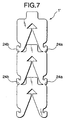
- a number of the binding clips connected with one another can be used by connecting the distal portions of both the leg portions of a binding clip with both shoulder portions formed at upper ends of both the leg portions of another binding clip at connecting parts 24a, 24b as shown in Fig. 7.
- a number of the binding clips thus connected with one another can be wound into a roll shape to form an assembly consisting of 500 to 2000 clips, and the assembly of the clips can be loaded in a binding machine, which is not shown, to conduct a binding operation, whereby a rapid binding operation can be continuously conducted.
- the binding clip according to the invention is so constructed that a pair of engaging projections are formed at portions continuing from the opening to the receiving portion for receiving the object to be bound, the engaging projections being adapted to overlap each other and project into the receiving portion for receiving the object to be bound when the leg portions are crossed. Therefore, when the bag, net or the like is bound, a force of the object coming out toward the crossed parts of the leg portions will be divided in the two directions by means of the engaging projections, thus preventing the object to be bound from coming out toward the crossed parts of the leg portions.
- the engaging projections are pressed against the plastic bag, net or the like which tends to expand, and the distal ends of the engaging projections hold the plastic bag, net or the like in a biting attitude, whereby the strong binding force can be obtained.
- the receiving portion for receiving the object to be bound is in a substantially triangular shape making the deepest end of the opening as the apex, the tapered portions consisting of the two edges with the deepest end as the apex act to press the plastic bag, net or the like toward the engaging projections, whereby the strong binding force can be obtained.
- the present invention is based on Japanese Patent Application No. Hei. 11-199563 which is incorporated herein by reference.
Landscapes
- Engineering & Computer Science (AREA)
- Mechanical Engineering (AREA)
- Auxiliary Apparatuses For Manual Packaging Operations (AREA)
- Bag Frames (AREA)
- Package Closures (AREA)
- Clamps And Clips (AREA)
- Insertion Pins And Rivets (AREA)
Applications Claiming Priority (2)
| Application Number | Priority Date | Filing Date | Title |
|---|---|---|---|
| JP19956399 | 1999-07-13 | ||
| JP19956399A JP3674395B2 (ja) | 1999-07-13 | 1999-07-13 | 結束用クリップ |
Publications (3)
| Publication Number | Publication Date |
|---|---|
| EP1069050A2 true EP1069050A2 (de) | 2001-01-17 |
| EP1069050A3 EP1069050A3 (de) | 2001-12-19 |
| EP1069050B1 EP1069050B1 (de) | 2004-09-29 |
Family
ID=16409920
Family Applications (1)
| Application Number | Title | Priority Date | Filing Date |
|---|---|---|---|
| EP00115218A Expired - Lifetime EP1069050B1 (de) | 1999-07-13 | 2000-07-13 | Klammer |
Country Status (4)
| Country | Link |
|---|---|
| US (1) | US6591460B1 (de) |
| EP (1) | EP1069050B1 (de) |
| JP (1) | JP3674395B2 (de) |
| DE (1) | DE60014260T2 (de) |
Cited By (1)
| Publication number | Priority date | Publication date | Assignee | Title |
|---|---|---|---|---|
| EP2444330A4 (de) * | 2009-06-15 | 2012-11-14 | Sung Hyun Kim | Klemme |
Families Citing this family (11)
| Publication number | Priority date | Publication date | Assignee | Title |
|---|---|---|---|---|
| NL1024491C2 (nl) * | 2003-10-09 | 2005-04-12 | Schutte Holding B V | Werkwijze voor het sluiten van een flexibele verpakking, een inrichting daarvoor en een gesloten flexibele verpakking. |
| US7565780B2 (en) * | 2005-02-04 | 2009-07-28 | Poly-Clip System Corp. | Clip and clipper |
| BRPI0707265A2 (pt) * | 2006-01-27 | 2011-04-26 | Poly Clip System Corp | grampo e grampeador |
| US9403630B2 (en) * | 2010-08-05 | 2016-08-02 | The Lindy Bowman Company | System, method and apparatus for gift bag binding |
| US8931242B1 (en) * | 2012-06-05 | 2015-01-13 | Louis Sardo | Stretchable gift wrap system |
| USD707553S1 (en) * | 2013-03-08 | 2014-06-24 | Joshua Vantrease | Enclosure fastener |
| USD880296S1 (en) | 2018-09-25 | 2020-04-07 | Klr Systems Inc. | Bag closure clip |
| USD871212S1 (en) | 2018-09-25 | 2019-12-31 | Klr Systems Inc. | Bag closure clip |
| USD1005104S1 (en) * | 2019-09-27 | 2023-11-21 | Bedford Industries, Inc. | Closure roll |
| US20220297891A1 (en) * | 2021-03-16 | 2022-09-22 | Frank Matte | Bag fastener for flexible bags |
| USD1028649S1 (en) * | 2023-05-10 | 2024-05-28 | Jikke Roos Amalia de Jong | Plant-clip |
Family Cites Families (22)
| Publication number | Priority date | Publication date | Assignee | Title |
|---|---|---|---|---|
| US3234616A (en) * | 1965-02-16 | 1966-02-15 | Edward F Wantland | Ring fasteners |
| US3535746A (en) * | 1966-11-07 | 1970-10-27 | Stanley E Thomas Jr | Reusable bag fastener |
| GB1446012A (en) | 1973-07-05 | 1976-08-11 | Britt J P | Packaging |
| US3882573A (en) * | 1974-01-02 | 1975-05-13 | Jr Stanley E Thomas | Flexible, reusable fastener |
| US3910811A (en) | 1974-07-18 | 1975-10-07 | Kwik Lok | Method and machine for removeably securing stiff plastic closures flat against series of moving packages |
| US4174554A (en) * | 1978-07-14 | 1979-11-20 | Bonar & Bemis Ltd. | Bag closure |
| US4357186A (en) | 1980-06-17 | 1982-11-02 | The Mead Corporation | Machine and method for forming and applying carrying straps to article cartons |
| JPS57125106A (en) | 1981-01-28 | 1982-08-04 | Toshiyuki Kokito | Packer for food |
| US4497091A (en) * | 1983-03-18 | 1985-02-05 | Elliott Jon S | Twist clip |
| US4896366A (en) | 1988-11-18 | 1990-01-23 | World Manufacturing, Inc. | T-shirt bag closure |
| US5269120A (en) | 1990-09-17 | 1993-12-14 | Kwik Lok Corporation | System for marking and installing closures |
| US5425826A (en) | 1991-06-28 | 1995-06-20 | The Boeing Company | Method and apparatus for forming a welded identification sleeve |
| JP2684937B2 (ja) * | 1992-09-07 | 1997-12-03 | マックス株式会社 | 結束方法および結束具 |
| US5286110A (en) * | 1993-04-01 | 1994-02-15 | Mickey Benson | Bag having tamper-resistant seal |
| US5485711A (en) * | 1993-08-20 | 1996-01-23 | Max Co., Ltd. | Binding machine |
| US5564255A (en) | 1994-09-28 | 1996-10-15 | Tetra Laval Holdings & Finance S.A. | Apparatus and method for sealing and creasing gabled containers |
| JP3355469B2 (ja) * | 1996-04-30 | 2002-12-09 | 保男 樋口 | 包装用袋口結束具 |
| US5782067A (en) | 1996-06-28 | 1998-07-21 | Free-Flow Packaging International, Inc. | Bag sealer and cutter for use in packaging loose fill packaging materials |
| JP3491462B2 (ja) | 1996-08-13 | 2004-01-26 | マックス株式会社 | 結束方法 |
| JP3147006B2 (ja) | 1996-10-08 | 2001-03-19 | マックス株式会社 | 袋結束機及び袋を結縛する結束方法 |
| DE69908196T2 (de) | 1998-02-16 | 2003-11-27 | Max Co. Ltd., Tokio/Tokyo | Bindemaschine |
| US6112499A (en) | 1999-01-19 | 2000-09-05 | Hellermanntyton Corporation | Bag closure apparatus |
-
1999
- 1999-07-13 JP JP19956399A patent/JP3674395B2/ja not_active Expired - Fee Related
-
2000
- 2000-07-12 US US09/614,703 patent/US6591460B1/en not_active Expired - Fee Related
- 2000-07-13 EP EP00115218A patent/EP1069050B1/de not_active Expired - Lifetime
- 2000-07-13 DE DE60014260T patent/DE60014260T2/de not_active Expired - Fee Related
Cited By (1)
| Publication number | Priority date | Publication date | Assignee | Title |
|---|---|---|---|---|
| EP2444330A4 (de) * | 2009-06-15 | 2012-11-14 | Sung Hyun Kim | Klemme |
Also Published As
| Publication number | Publication date |
|---|---|
| US6591460B1 (en) | 2003-07-15 |
| JP3674395B2 (ja) | 2005-07-20 |
| EP1069050A3 (de) | 2001-12-19 |
| DE60014260T2 (de) | 2005-02-03 |
| DE60014260D1 (de) | 2004-11-04 |
| JP2001031029A (ja) | 2001-02-06 |
| EP1069050B1 (de) | 2004-09-29 |
Similar Documents
| Publication | Publication Date | Title |
|---|---|---|
| EP1069050A2 (de) | Klammer | |
| US3722670A (en) | Clip stack | |
| CA2009209C (en) | Closure strip | |
| JPH02292506A (ja) | 2個の閉鎖エッジを連結するための装置を有するクランプを備えた管クランプまたは管クランプとして用いたプレスリングおよびその製造方法 | |
| US5314065A (en) | Sheet metal clip | |
| US7937813B2 (en) | Clip | |
| US5303821A (en) | Resilient clip assembly | |
| AU629766B1 (en) | Binding strap with integral connecting structure and anti-disengagement feature | |
| US5927491A (en) | Resilient U-clip assembly | |
| US5682994A (en) | Collated clip assembly | |
| US5314064A (en) | Sheet metal clip | |
| US2393514A (en) | Wallboard package and holder | |
| US8122571B2 (en) | Closure clip and process for the production thereof | |
| US5878880A (en) | Collated clip assembly | |
| US4860532A (en) | Method for joining together two segments of a snow-chain, and connecting element to implement the method | |
| US3197831A (en) | Ligature joint and seal therefor | |
| US20060168768A1 (en) | Sealed joint devices for securing strap ends together | |
| JP2002362590A (ja) | クリップ及びクリップ用クリンチャー | |
| JP3025877B2 (ja) | ゴム紐結束具 | |
| AU2010202502B2 (en) | Clip | |
| US20250376293A1 (en) | Box closure clip | |
| JP2005153433A (ja) | レールホルダー | |
| JP3005271U (ja) | 抜け防止機能を備えたステープル | |
| JP2004067199A (ja) | 結束具および結束装置並びに結束方法 | |
| JPS61244746A (ja) | 裂開可能な缶部材 |
Legal Events
| Date | Code | Title | Description |
|---|---|---|---|
| PUAI | Public reference made under article 153(3) epc to a published international application that has entered the european phase |
Free format text: ORIGINAL CODE: 0009012 |
|
| AK | Designated contracting states |
Kind code of ref document: A2 Designated state(s): AT BE CH CY DE DK ES FI FR GB GR IE IT LI LU MC NL PT SE Kind code of ref document: A2 Designated state(s): DE FR GB |
|
| AX | Request for extension of the european patent |
Free format text: AL;LT;LV;MK;RO;SI |
|
| PUAL | Search report despatched |
Free format text: ORIGINAL CODE: 0009013 |
|
| AK | Designated contracting states |
Kind code of ref document: A3 Designated state(s): AT BE CH CY DE DK ES FI FR GB GR IE IT LI LU MC NL PT SE |
|
| AX | Request for extension of the european patent |
Free format text: AL;LT;LV;MK;RO;SI |
|
| 17P | Request for examination filed |
Effective date: 20020606 |
|
| AKX | Designation fees paid |
Free format text: DE FR GB |
|
| 17Q | First examination report despatched |
Effective date: 20021001 |
|
| GRAP | Despatch of communication of intention to grant a patent |
Free format text: ORIGINAL CODE: EPIDOSNIGR1 |
|
| GRAS | Grant fee paid |
Free format text: ORIGINAL CODE: EPIDOSNIGR3 |
|
| GRAA | (expected) grant |
Free format text: ORIGINAL CODE: 0009210 |
|
| AK | Designated contracting states |
Kind code of ref document: B1 Designated state(s): DE FR GB |
|
| REG | Reference to a national code |
Ref country code: GB Ref legal event code: FG4D |
|
| REG | Reference to a national code |
Ref country code: IE Ref legal event code: FG4D |
|
| REF | Corresponds to: |
Ref document number: 60014260 Country of ref document: DE Date of ref document: 20041104 Kind code of ref document: P |
|
| ET | Fr: translation filed | ||
| PLBE | No opposition filed within time limit |
Free format text: ORIGINAL CODE: 0009261 |
|
| STAA | Information on the status of an ep patent application or granted ep patent |
Free format text: STATUS: NO OPPOSITION FILED WITHIN TIME LIMIT |
|
| 26N | No opposition filed |
Effective date: 20050630 |
|
| PGFP | Annual fee paid to national office [announced via postgrant information from national office to epo] |
Ref country code: FR Payment date: 20090710 Year of fee payment: 10 |
|
| PGFP | Annual fee paid to national office [announced via postgrant information from national office to epo] |
Ref country code: DE Payment date: 20090709 Year of fee payment: 10 Ref country code: GB Payment date: 20090708 Year of fee payment: 10 |
|
| GBPC | Gb: european patent ceased through non-payment of renewal fee |
Effective date: 20100713 |
|
| REG | Reference to a national code |
Ref country code: FR Ref legal event code: ST Effective date: 20110331 |
|
| PG25 | Lapsed in a contracting state [announced via postgrant information from national office to epo] |
Ref country code: DE Free format text: LAPSE BECAUSE OF NON-PAYMENT OF DUE FEES Effective date: 20110201 |
|
| REG | Reference to a national code |
Ref country code: DE Ref legal event code: R119 Ref document number: 60014260 Country of ref document: DE Effective date: 20110201 |
|
| PG25 | Lapsed in a contracting state [announced via postgrant information from national office to epo] |
Ref country code: FR Free format text: LAPSE BECAUSE OF NON-PAYMENT OF DUE FEES Effective date: 20100802 |
|
| PG25 | Lapsed in a contracting state [announced via postgrant information from national office to epo] |
Ref country code: GB Free format text: LAPSE BECAUSE OF NON-PAYMENT OF DUE FEES Effective date: 20100713 |