EP1069019A1 - Dispositif pour realiser une connexion électrique - Google Patents
Dispositif pour realiser une connexion électrique Download PDFInfo
- Publication number
- EP1069019A1 EP1069019A1 EP00113087A EP00113087A EP1069019A1 EP 1069019 A1 EP1069019 A1 EP 1069019A1 EP 00113087 A EP00113087 A EP 00113087A EP 00113087 A EP00113087 A EP 00113087A EP 1069019 A1 EP1069019 A1 EP 1069019A1
- Authority
- EP
- European Patent Office
- Prior art keywords
- plug
- electrical
- realizing
- segments
- coupling
- Prior art date
- Legal status (The legal status is an assumption and is not a legal conclusion. Google has not performed a legal analysis and makes no representation as to the accuracy of the status listed.)
- Granted
Links
- 230000008878 coupling Effects 0.000 claims abstract description 63
- 238000010168 coupling process Methods 0.000 claims abstract description 63
- 238000005859 coupling reaction Methods 0.000 claims abstract description 63
- 238000003780 insertion Methods 0.000 claims abstract description 36
- 230000037431 insertion Effects 0.000 claims abstract description 36
- 230000000295 complement effect Effects 0.000 claims abstract description 14
- 238000009434 installation Methods 0.000 claims description 3
- 238000013461 design Methods 0.000 description 15
- 230000001050 lubricating effect Effects 0.000 description 6
- 238000000926 separation method Methods 0.000 description 6
- 230000008901 benefit Effects 0.000 description 3
- 239000004020 conductor Substances 0.000 description 2
- 239000000428 dust Substances 0.000 description 2
- 238000005242 forging Methods 0.000 description 2
- 238000009413 insulation Methods 0.000 description 2
- 238000005461 lubrication Methods 0.000 description 2
- 238000004519 manufacturing process Methods 0.000 description 2
- 239000000463 material Substances 0.000 description 2
- 238000000034 method Methods 0.000 description 2
- 238000003825 pressing Methods 0.000 description 2
- 230000008569 process Effects 0.000 description 2
- 230000000717 retained effect Effects 0.000 description 2
- 239000004576 sand Substances 0.000 description 2
- 230000009471 action Effects 0.000 description 1
- 230000015572 biosynthetic process Effects 0.000 description 1
- 239000012876 carrier material Substances 0.000 description 1
- 238000004140 cleaning Methods 0.000 description 1
- 239000011248 coating agent Substances 0.000 description 1
- 238000000576 coating method Methods 0.000 description 1
- 238000005520 cutting process Methods 0.000 description 1
- 238000011161 development Methods 0.000 description 1
- 230000000694 effects Effects 0.000 description 1
- 230000007613 environmental effect Effects 0.000 description 1
- 230000003993 interaction Effects 0.000 description 1
- 238000012423 maintenance Methods 0.000 description 1
- 230000013011 mating Effects 0.000 description 1
- 239000007769 metal material Substances 0.000 description 1
Images

Classifications
-
- B—PERFORMING OPERATIONS; TRANSPORTING
- B61—RAILWAYS
- B61G—COUPLINGS; DRAUGHT AND BUFFING APPLIANCES
- B61G5/00—Couplings for special purposes not otherwise provided for
- B61G5/06—Couplings for special purposes not otherwise provided for for, or combined with, couplings or connectors for fluid conduits or electric cables
- B61G5/10—Couplings for special purposes not otherwise provided for for, or combined with, couplings or connectors for fluid conduits or electric cables for electric cables
-
- H—ELECTRICITY
- H01—ELECTRIC ELEMENTS
- H01R—ELECTRICALLY-CONDUCTIVE CONNECTIONS; STRUCTURAL ASSOCIATIONS OF A PLURALITY OF MUTUALLY-INSULATED ELECTRICAL CONNECTING ELEMENTS; COUPLING DEVICES; CURRENT COLLECTORS
- H01R35/00—Flexible or turnable line connectors, i.e. the rotation angle being limited
- H01R35/04—Turnable line connectors with limited rotation angle with frictional contact members
Definitions
- the invention relates to a device for realizing an electrical plug connection an electric coupling device for an automatic train coupling according to the preamble of claim 1, further an electric coupling device and a automatic train coupling with such an electric coupling device.
- Automatic train couplings enable the automated connection of two Rail vehicles, in the coupled state two such couplings one Establish a rigid connection between the vehicles.
- An automatic train coupling has become known from EP 05 01 244, comprising a coupling head as well as a cable coupling with elastic at the front push-back and in the coupling state pneumatically forward, in the pressing direction to a mating line coupling head, loaded line coupling head.
- DE 43 10 741 shows an automatic train coupling with a coupling body and an electric clutch, which subsequently, i.e. after finishing mechanical Coupling, coupling.
- Such a coupling must be up to the compensation certain transverse play between the mechanical couplings only in the longitudinal direction be moved.
- the electric clutch known from DE 43 10 741 is designed such that the Electric clutch is released before mechanical decoupling, so that by the transverse movements forced by the mechanical coupling the longitudinal guidance the electrical coupling is not damaged.
- All described coupling devices each comprise at least one device to realize an electrical connection in the form of an electrical Plug connection, comprising a plug device and a plug element.
- This Functions are achieved, for example, through the interaction of pin contacts realized with a socket, butt contacts or knife contacts.
- a generic Plug connection comprising a plug device with at least one first electrical contact, which with a complementary second electrical Contact of a plug-in element by inserting and touching each other the contact surfaces can be brought into active connection, is from the publication DE 43 16 902 A1 known.
- the contact surfaces of the electrical contacts are from Plug devices and plug element viewed in cross section in the installation position, in an angle to the theoretical insertion axis of the plug element into the plug device aligned and the contact surfaces themselves are designed as lubricating surfaces.
- the invention is therefore based on the object of a device for implementation an electrical connection, in particular an electrical connector for the use in electric coupling devices for an automatic train coupling such to further develop that the disadvantages of the prior art are avoided, especially the susceptibility to failure by ensuring a safe electrical Connection is significantly reduced even under load.
- the electric clutch should Adequate both in the coupled and in the uncoupled position Protection against weather and environmental influences, especially pollution exhibit.
- the one to be used to implement and maintain the electrical connection should be as low as possible, while at the same time high separation and coupling speeds, i.e. high speeds in the implementation of the electrical coupling and the disconnection process, i.e. the solution of the electrical coupling are desired.
- In the axial direction i.e. viewed in the installation position in the direction of the theoretical connection axis of the two rail vehicles to be connected by means of the automatic train coupling or Waggongs, is within the interlocking game of the electric coupling electrical contact and thus the electrical connection at all times and ensure under disruptive influences, i.e. for example, even with strong ones Vibrations in this direction. Because of the purpose and the knotted in it Requirements for any downtimes and changeover times to be provided should the device for realizing the electrical connection through a high Mark downtime and low maintenance.
- the device for realizing an electrical connection comprises one, at least a first electrical contact or a plurality of first electrical Contacts-carrying connector and one, at least a second electrical Contact or plug-in element carrying a plurality of second electrical contacts, the first contacts with the to realize the electrical connection second contacts can be brought into active connection.
- the electrical contacts are connected with corresponding connecting lines.
- this is achieved by the curved formation of the contact surfaces on the plug device or on Plug element as a sliding surface, which is at an angle to the insertion axis of the Plug element considered in the plug device in cross section of the device are aligned, realized.
- the sliding surfaces on the plug element are included can be described by at least two different radii.
- the plug element complementary plug contacts of the plug device are preferably in cross section considered circular and form the to the surface to be smeared on Plug-in element complementary contact surface, which is only a radius can be described.
- the alignment at an angle to the insertion axis and the arcuate configuration enable provision even with little force on the plug element a high contact pressure.
- the sliding surfaces on the plug element are due to the geometric design viewed in cross section generated in the form of a toggle lever. This forms in the coupling area Lubricating surfaces, which realize an electrical contact enable by touching the surface.
- the electrical contacts are on the sliding surfaces arranged or are made of an electrical when the plug element conductive material formed by this.
- the connecting lines extend themselves in the electrical plug-in element up to the sliding surfaces and step over them when coupling with the plug device with the contacts contained in it Active connection.
- the solution according to the invention makes it possible in a simple and reliable manner and Way to make electrical contacts. Due to the design of the active connection Stepping areas with surface contact can be used to create and maintain of the contact required force from the state of the Technically known designs can be kept considerably lower.
- the toggle action enables automatic train couplings when used in electrical couplings a safe contact with large vibrations occurring in the axial Direction, i.e. in the direction of the theoretical connection axis of the automatic Train coupling rail vehicles to be coupled.
- the geometrical Design of the plug-in element with toggle lever and sliding surfaces with a complementary arrangement and configuration of the cross section in theory possible contact area circular contact surfaces of the plug device furthermore enables the implementation of a small coupling path.
- the contact path in the axial direction is compared to that in the prior art known versions significantly lower. Because most of the total Frictional resistance occurs at the contact point, the coupling and separation energy be kept small.
- Another advantage is that due to the small coupling path as well of the surface contact, the friction path is low due to the small plug path can be held.
- the relative movement of the contact surfaces on the connector element opposite the contact surfaces in the connector is determined, which creates a self-cleaning effect is achieved.
- the plug device has a socket on which is designed as a spring clip segment and which the connector segments resiliently supported.
- the connector segments are also in the Cross-section considered, can be divided into at least three sub-areas, a first Partial area, which is designed as a projection and which in the bulge of the Socket engages a second section that carries the electrical contacts and a third section which is complementary to the toggle lever of the plug element Contour, however, has a larger dimension and thus a positive Carrying the plug element under certain operating conditions enables.
- the toggle lever can also be used at high speeds or when stiff an electrical connection can be reliably established.
- the geometric design enables it also that in the axial direction within the interlocking game the electrical coupling, even with large vibrations, an electrical contact can be produced. At high separation speeds, the contact is achieved by positive locking returned to its original position.
- the socket is on the insertion side the side facing away from the plug-in element is preferably designed to be open. Together with the V-shaped configuration of the individual segments the possibility of easy removal of deposits, e.g. Dust, sand e.t.c.
- the device designed according to the invention for realizing an electrical connection is very versatile.
- a preferred use is for those Applications in which to provide high contact forces with a small plug force are.
- An example of this are electric coupling devices used in automatic train couplings can be used.
- FIG. 1a illustrates an embodiment of an embodiment designed according to the invention Device for realizing an electrical connection 1, comprising a, first electrical contacts 2 carrying connector 3 and a second electrical contacts 4 supporting plug-in element 5, which by coupling an electrical Connection between the one connected to the plug device 3 and the plug element 5, or connected to these electrical line systems, here representative 6a and 6d for the electrical contacts 2a and 2d of the plug-in device 3 and 7a and 7d for the electrical contacts 4a and 4d of the plug element 5.
- the connector 3 carries six electrical contacts in the case shown. This are corresponding to the plug-in device 3 in a view from above in FIG. 1c reproduced in the representation in Figure 1a and marked with 2a - 2f.
- the Plug-in element 5 carries the complementary that can be brought into operative connection therewith executed electrical contacts 4a to 4f, as in the view I-I of FIG. 1a in Figure 1c shown.
- the connector 3 is for this purpose in six connector segments 3a to 3f and the plug element in six plug element segments 5a to 5f divided. These segments can be made of plastic. Only in the area of the contact areas these are then used to implement the function with a electrical contact material coated, which with the electrical connection lines 6a to 6f or 7a to 7f is connected.
- plug element segments 5a to 5f and plug device segments 3a to 3f made entirely of an electrically conductive material, to manufacture, for example, metallic material, the contact surfaces being none at all require a separate coating. In this case there are between the individual segments However, appropriate insulation must be provided to ensure functionality and To ensure security.
- the coupling is done mechanically and electrically.
- the electrical Contacts 4a to 4f of the plug element and 2a to 2f of the plug device can be written on and contact surfaces that can be brought into operative connection as The cross-section of the sliding surfaces 8a to 8f and 9a to 9f viewed in this manner carried out that the contact between the electrical contacts 4a to 4f and 2a to 2f even with a theoretically possible relative movement of plug element 5 to plug device 3 of small size (longitudinal play compensation) in the direction of the insertion axis A of the plug element 5 is retained in the plug device 3.
- the plug element 5 complementary electrical contacts 2a to 2f or through them in cross section considered writable surfaces 8a to 8f on the connector 3 are preferably of circular design and form the sliding surface 9a to 9f on the plug-in element 5 complementary contact surfaces, which are characterized by only one Let radius be described.
- the contact surfaces of the electrical contacts are viewed in the coupled state of plug device 3 and plug element 5 in aligned at an angle to the insertion axis A.
- the plug element 5 is in its end region 10 in the direction of insertion of the plug element 5 into the plug device 3 viewed in cross section in the individual segments 5a to 5f in the form of a toggle lever.
- the geometric design as a toggle lever offers in addition to the arcuate design in cross section Schmiege vom 9a-9f the advantage that when executing the connector 3 in Coupling area with larger recess corresponding to the toggle lever Dimension during the separation process, i.e. the disconnection of the electrical connection a positive entrainment in the starting position at high cutting speed he follows.
- the plug device 3 comprises a socket 11, which as Spring clip segment is executed and in which the individual connector segments 2a to 2f are supported and supported elastically.
- the single ones Plug device segments 3a to 3f are in a view II-II according to Figure 1a as in Figure 1c shown V-shaped, the end regions 12.1a, 12.1b-12.6a, 12.6b of the individual legs 12.1 to 12.6 in a bulge 13 of the socket 11 intervene. Viewed in cross section, as shown in FIG.
- each is Segments 3a to 3f can be subdivided into at least three partial areas, a first one Partial area 14, which is designed as a projection and which extends into the bulge 13 the socket 11 engages a second portion 15, which is the electrical contacts 2 carries and a third portion 16, which one to the toggle of the plug element 5 has complementary contour but with larger dimensions and thus a form-fitting entrainment of the plug element 5 under certain operating conditions enables.
- the socket 11 is on the insertion side of the plug element 5 opposite side preferably carried out open. Together with the V-shaped configuration of the individual segments 3a to 3f is therefore possible easy removal of deposits, e.g. Dust, sand e.t.c.
- the Lubrication surfaces 8a-8f of the plug device and the lubrication surfaces 9a to 9f of the Plug elements are viewed in the circumferential direction to the insertion axis in the figures 1 aligned in this direction and straight. There is also this here Possibility of aligning the sliding surfaces in the circumferential direction, not shown to the insertion axis A on a certain diameter.
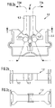
- FIG. 2a to 2c illustrate a further embodiment of an inventive designed device for realizing an electrical connection 1.2 in Flat arrangement.
- the basic structure corresponds essentially to that in FIG. 1 described, which is why the same reference numerals are used for the same elements become.
- the flat arrangement is characterized in that plug device 3.2 and connector element 5.2 in a view from above, i.e. on the insertion axis A. a rectangular contour can be written on.
- the sliding surfaces 8a.2 and 8b.2 of the Plug device 3.2 are viewed in the cross section of the device 1.2 as a circular arc educated.
- the view from above according to FIG. 2b illustrates one embodiment of the sliding surfaces parallel to the insertion axis or a plane, which through the insertion axis A and a perpendicular to this can be written.
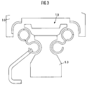
- FIG. 3 illustrates an alternative embodiment of a device for implementation an electrical connection 1.3, in which the contact surfaces form Elements of the plug element 5.3 are each formed by a spring clip.
Landscapes
- Engineering & Computer Science (AREA)
- Mechanical Engineering (AREA)
- Connector Housings Or Holding Contact Members (AREA)
- Details Of Connecting Devices For Male And Female Coupling (AREA)
Applications Claiming Priority (2)
| Application Number | Priority Date | Filing Date | Title |
|---|---|---|---|
| DE19932469A DE19932469C2 (de) | 1999-07-12 | 1999-07-12 | Vorrichtung zur Realisierung einer elektrischen Steckverbindung |
| DE19932469 | 1999-07-12 |
Publications (2)
| Publication Number | Publication Date |
|---|---|
| EP1069019A1 true EP1069019A1 (fr) | 2001-01-17 |
| EP1069019B1 EP1069019B1 (fr) | 2003-01-29 |
Family
ID=7914452
Family Applications (1)
| Application Number | Title | Priority Date | Filing Date |
|---|---|---|---|
| EP00113087A Expired - Lifetime EP1069019B1 (fr) | 1999-07-12 | 2000-06-27 | Dispositif pour realiser une connexion électrique |
Country Status (2)
| Country | Link |
|---|---|
| EP (1) | EP1069019B1 (fr) |
| DE (2) | DE19932469C2 (fr) |
Citations (3)
| Publication number | Priority date | Publication date | Assignee | Title |
|---|---|---|---|---|
| DE1563964A1 (de) * | 1964-02-24 | 1971-01-28 | Licentia Gmbh | Automatische elektrische Kupplung fuer die Heiz- und Steuerstromkreise von Vollbahnen |
| US5833482A (en) * | 1995-09-08 | 1998-11-10 | The Whitaker Corporation | Pivotable electrical connector |
| WO1999032343A1 (fr) * | 1997-12-18 | 1999-07-01 | Knorr-Bremse Systeme für Schienenfahrzeuge GmbH | Dispositif d'assemblage pour l'assemblage par enfichage d'une prise male et d'une prise femelle |
Family Cites Families (4)
| Publication number | Priority date | Publication date | Assignee | Title |
|---|---|---|---|---|
| DE1008377B (de) * | 1953-02-20 | 1957-05-16 | Bergische Stahlindustrie | Druckkontakt fuer elektrische Leitungen, insbesondere bei Fahrzeugkupplungen |
| DE4106421A1 (de) * | 1991-02-28 | 1992-09-03 | Knorr Bremse Ag | Selbsttaetige kupplung fuer schienenfahrzeuge |
| FR2691584A1 (fr) * | 1992-05-21 | 1993-11-26 | Drogo Pierre | Connecteur électrique et dispositif de connexion électrique comportant au moins un tel connecteur. |
| DE4310741A1 (de) * | 1993-04-01 | 1994-10-06 | Knorr Bremse Ag | Automatische Kupplung für Schienenfahrzeuge |
-
1999
- 1999-07-12 DE DE19932469A patent/DE19932469C2/de not_active Expired - Fee Related
-
2000
- 2000-06-27 EP EP00113087A patent/EP1069019B1/fr not_active Expired - Lifetime
- 2000-06-27 DE DE50001157T patent/DE50001157D1/de not_active Expired - Lifetime
Patent Citations (3)
| Publication number | Priority date | Publication date | Assignee | Title |
|---|---|---|---|---|
| DE1563964A1 (de) * | 1964-02-24 | 1971-01-28 | Licentia Gmbh | Automatische elektrische Kupplung fuer die Heiz- und Steuerstromkreise von Vollbahnen |
| US5833482A (en) * | 1995-09-08 | 1998-11-10 | The Whitaker Corporation | Pivotable electrical connector |
| WO1999032343A1 (fr) * | 1997-12-18 | 1999-07-01 | Knorr-Bremse Systeme für Schienenfahrzeuge GmbH | Dispositif d'assemblage pour l'assemblage par enfichage d'une prise male et d'une prise femelle |
Also Published As
| Publication number | Publication date |
|---|---|
| EP1069019B1 (fr) | 2003-01-29 |
| DE50001157D1 (de) | 2003-03-06 |
| DE19932469A1 (de) | 2001-02-08 |
| DE19932469C2 (de) | 2001-05-17 |
Similar Documents
| Publication | Publication Date | Title |
|---|---|---|
| EP2441129B1 (fr) | Contact à insérer pour relier un composant électronique à une carte de circuits imprimés ainsi qu'outil d'insertion et procédé pour fabriquer un contact à insérer | |
| DE60210073T2 (de) | Optische steckeranordnung zur verbindung mehrerer glasfasern | |
| DE69724011T2 (de) | Optischer steckverbinder | |
| DE69904119T2 (de) | Faseroptischer Verbinder in dem eine optische Faser auch dann geschützt wird, wenn die Verbindung nicht hergestellt ist | |
| EP4000137B1 (fr) | Élément de contact pour relier électriquement des cartes à circuit imprimé et procédé d'assemblage d'un arrangement de cartes à circuit imprimé | |
| DE69705658T2 (de) | Modularer Aufbau, bestehend aus mehreren Einheiten, mit den entsprechenden Steckverbindern | |
| EP2339701A2 (fr) | Connecteur à fiche de plaquettes doté d'un dispositif de verrouillage | |
| WO2013186111A1 (fr) | Système adaptateur de balai d'essuie-glace | |
| DE102017118014B3 (de) | Steckverbinderteil mit einem Verriegelungselement | |
| DE10140153B4 (de) | Steckverbindung zum gleichzeitigen Verbinden mehrerer Koaxialkabel | |
| EP0887896A2 (fr) | Connecteur électrique | |
| DE2824507C2 (de) | Steckvorrichtung zur elektromagnetischen Kopplung von optischen Faserleitern | |
| DE102017001943A1 (de) | Anschlusssystem | |
| EP3981046B1 (fr) | Connecteur de carte de circuit imprimé modulaire | |
| DE102018000940A1 (de) | Steckverbinder und Kontaktanordnung | |
| DE69131026T2 (de) | Optischer Steckverbinder mit Adapter mit Vorrichtung zum Schliessen und Trennen des optischen Kontakts | |
| DE202012005124U1 (de) | Vorrichtung für die Kontaktierung eines LED-Bandes sowie Vorrichtung für die elektrisch leitende Verbindung mindestens zweier LED-Bänder | |
| DE102016200243A1 (de) | Kontaktverbinder, Anschlusskontakt und Verfahren zur Herstellung eines Kontaktverbinders | |
| DE102024131689A1 (de) | Verbinder | |
| EP1069019B1 (fr) | Dispositif pour realiser une connexion électrique | |
| WO1989002167A1 (fr) | Dispositif de raccordement electrique | |
| EP1381118B1 (fr) | Connecteur symétrique | |
| EP2195887B1 (fr) | Connecteur de matrice multipolaire | |
| CH654420A5 (de) | Loesbare optische steckerverbindung. | |
| EP0419891B1 (fr) | Outil manuel pour terminer un câble plat dans un connecteur |
Legal Events
| Date | Code | Title | Description |
|---|---|---|---|
| PUAI | Public reference made under article 153(3) epc to a published international application that has entered the european phase |
Free format text: ORIGINAL CODE: 0009012 |
|
| AK | Designated contracting states |
Kind code of ref document: A1 Designated state(s): DE FR GB SE |
|
| AX | Request for extension of the european patent |
Free format text: AL;LT;LV;MK;RO;SI |
|
| 17P | Request for examination filed |
Effective date: 20010717 |
|
| AKX | Designation fees paid |
Free format text: DE FR GB SE |
|
| 17Q | First examination report despatched |
Effective date: 20010918 |
|
| GRAG | Despatch of communication of intention to grant |
Free format text: ORIGINAL CODE: EPIDOS AGRA |
|
| GRAG | Despatch of communication of intention to grant |
Free format text: ORIGINAL CODE: EPIDOS AGRA |
|
| GRAH | Despatch of communication of intention to grant a patent |
Free format text: ORIGINAL CODE: EPIDOS IGRA |
|
| GRAH | Despatch of communication of intention to grant a patent |
Free format text: ORIGINAL CODE: EPIDOS IGRA |
|
| GRAA | (expected) grant |
Free format text: ORIGINAL CODE: 0009210 |
|
| AK | Designated contracting states |
Designated state(s): DE FR GB SE |
|
| REG | Reference to a national code |
Ref country code: GB Ref legal event code: FG4D Free format text: NOT ENGLISH |
|
| REF | Corresponds to: |
Ref document number: 50001157 Country of ref document: DE Date of ref document: 20030306 Kind code of ref document: P |
|
| GBT | Gb: translation of ep patent filed (gb section 77(6)(a)/1977) |
Effective date: 20030315 |
|
| ET | Fr: translation filed | ||
| PLBE | No opposition filed within time limit |
Free format text: ORIGINAL CODE: 0009261 |
|
| STAA | Information on the status of an ep patent application or granted ep patent |
Free format text: STATUS: NO OPPOSITION FILED WITHIN TIME LIMIT |
|
| 26N | No opposition filed |
Effective date: 20031030 |
|
| PG25 | Lapsed in a contracting state [announced via postgrant information from national office to epo] |
Ref country code: GB Free format text: LAPSE BECAUSE OF NON-PAYMENT OF DUE FEES Effective date: 20040627 |
|
| GBPC | Gb: european patent ceased through non-payment of renewal fee |
Effective date: 20040627 |
|
| PGFP | Annual fee paid to national office [announced via postgrant information from national office to epo] |
Ref country code: FR Payment date: 20050621 Year of fee payment: 6 |
|
| PGFP | Annual fee paid to national office [announced via postgrant information from national office to epo] |
Ref country code: SE Payment date: 20050629 Year of fee payment: 6 |
|
| PG25 | Lapsed in a contracting state [announced via postgrant information from national office to epo] |
Ref country code: SE Free format text: LAPSE BECAUSE OF NON-PAYMENT OF DUE FEES Effective date: 20060628 |
|
| EUG | Se: european patent has lapsed | ||
| REG | Reference to a national code |
Ref country code: FR Ref legal event code: ST Effective date: 20070228 |
|
| PG25 | Lapsed in a contracting state [announced via postgrant information from national office to epo] |
Ref country code: FR Free format text: LAPSE BECAUSE OF NON-PAYMENT OF DUE FEES Effective date: 20060630 |
|
| PGFP | Annual fee paid to national office [announced via postgrant information from national office to epo] |
Ref country code: DE Payment date: 20100825 Year of fee payment: 11 |
|
| REG | Reference to a national code |
Ref country code: DE Ref legal event code: R119 Ref document number: 50001157 Country of ref document: DE Effective date: 20120103 |
|
| PG25 | Lapsed in a contracting state [announced via postgrant information from national office to epo] |
Ref country code: DE Free format text: LAPSE BECAUSE OF NON-PAYMENT OF DUE FEES Effective date: 20120103 |