EP1068614B1 - Abspielgerät - Google Patents
Abspielgerät Download PDFInfo
- Publication number
- EP1068614B1 EP1068614B1 EP99924780A EP99924780A EP1068614B1 EP 1068614 B1 EP1068614 B1 EP 1068614B1 EP 99924780 A EP99924780 A EP 99924780A EP 99924780 A EP99924780 A EP 99924780A EP 1068614 B1 EP1068614 B1 EP 1068614B1
- Authority
- EP
- European Patent Office
- Prior art keywords
- plate
- disk
- storage
- annular
- playback device
- Prior art date
- Legal status (The legal status is an assumption and is not a legal conclusion. Google has not performed a legal analysis and makes no representation as to the accuracy of the status listed.)
- Expired - Lifetime
Links
- 239000000463 material Substances 0.000 claims description 19
- 230000001133 acceleration Effects 0.000 claims description 12
- 239000011148 porous material Substances 0.000 claims description 9
- 239000004753 textile Substances 0.000 claims description 3
- 230000010355 oscillation Effects 0.000 claims 1
- 238000013016 damping Methods 0.000 description 21
- 239000010410 layer Substances 0.000 description 9
- 230000003287 optical effect Effects 0.000 description 7
- 230000008901 benefit Effects 0.000 description 5
- 230000008859 change Effects 0.000 description 4
- 239000003795 chemical substances by application Substances 0.000 description 3
- 238000005259 measurement Methods 0.000 description 2
- 239000011241 protective layer Substances 0.000 description 2
- 230000009467 reduction Effects 0.000 description 2
- 230000004044 response Effects 0.000 description 2
- 238000006748 scratching Methods 0.000 description 2
- 230000002393 scratching effect Effects 0.000 description 2
- 238000001228 spectrum Methods 0.000 description 2
- 238000011161 development Methods 0.000 description 1
- 230000018109 developmental process Effects 0.000 description 1
- 239000013013 elastic material Substances 0.000 description 1
- 239000003292 glue Substances 0.000 description 1
- 238000007373 indentation Methods 0.000 description 1
- 230000007774 longterm Effects 0.000 description 1
- 230000007246 mechanism Effects 0.000 description 1
- 239000002184 metal Substances 0.000 description 1
- 238000000034 method Methods 0.000 description 1
- 230000008569 process Effects 0.000 description 1
- 239000000523 sample Substances 0.000 description 1
- 230000035945 sensitivity Effects 0.000 description 1
- 230000035939 shock Effects 0.000 description 1
- 239000000725 suspension Substances 0.000 description 1
Images

Classifications
-
- G—PHYSICS
- G11—INFORMATION STORAGE
- G11B—INFORMATION STORAGE BASED ON RELATIVE MOVEMENT BETWEEN RECORD CARRIER AND TRANSDUCER
- G11B17/00—Guiding record carriers not specifically of filamentary or web form, or of supports therefor
- G11B17/02—Details
- G11B17/022—Positioning or locking of single discs
- G11B17/028—Positioning or locking of single discs of discs rotating during transducing operation
- G11B17/0282—Positioning or locking of single discs of discs rotating during transducing operation by means provided on the turntable
-
- G—PHYSICS
- G11—INFORMATION STORAGE
- G11B—INFORMATION STORAGE BASED ON RELATIVE MOVEMENT BETWEEN RECORD CARRIER AND TRANSDUCER
- G11B17/00—Guiding record carriers not specifically of filamentary or web form, or of supports therefor
- G11B17/02—Details
- G11B17/022—Positioning or locking of single discs
- G11B17/028—Positioning or locking of single discs of discs rotating during transducing operation
- G11B17/0284—Positioning or locking of single discs of discs rotating during transducing operation by clampers
-
- G—PHYSICS
- G11—INFORMATION STORAGE
- G11B—INFORMATION STORAGE BASED ON RELATIVE MOVEMENT BETWEEN RECORD CARRIER AND TRANSDUCER
- G11B19/00—Driving, starting, stopping record carriers not specifically of filamentary or web form, or of supports therefor; Control thereof; Control of operating function ; Driving both disc and head
- G11B19/20—Driving; Starting; Stopping; Control thereof
- G11B19/2009—Turntables, hubs and motors for disk drives; Mounting of motors in the drive
- G11B19/2018—Incorporating means for passive damping of vibration, either in the turntable, motor or mounting
-
- G—PHYSICS
- G11—INFORMATION STORAGE
- G11B—INFORMATION STORAGE BASED ON RELATIVE MOVEMENT BETWEEN RECORD CARRIER AND TRANSDUCER
- G11B33/00—Constructional parts, details or accessories not provided for in the other groups of this subclass
- G11B33/02—Cabinets; Cases; Stands; Disposition of apparatus therein or thereon
- G11B33/08—Insulation or absorption of undesired vibrations or sounds
Definitions
- the invention relates to a player of the type of the main claim.
- US-A-4 641 152 discloses a player according to the preamble of Main claim 1.
- the player of the invention with the features of The main claim has the advantage that between the disk and the first disk within one a predetermined distance is provided and that the range and distance are selected so that in the event of vibrations occurring approximately perpendicular to the plate levels the player with one not over one acceleration given a value an amplitude a resulting vibration of an outer edge of the Disk in relation to a center of the Storage disk results below a given one Value.
- This way through the air layer between the storage disk and the first disk in the predetermined Area and by the volume change between the Disk and the first disk in the specified area when the disk vibrates, especially at the resonance frequency the disk the vibration of the Storage disk can be steamed without additional Damping agents are required.
- the air layer between the storage disk and the first disk in the given one Area and the volume change between the disk and the first plate in the predetermined area at the Vibration of the storage disk thus acts as a damping means.
- Another advantage is that position errors at focusing tracks of an optical disc by a light beam from a reading device for scanning of the information stored in the tracks at vertical vibrations of the storage disk occurring at the disk level can be largely suppressed, so that the reading device is very resistant to vibrations the player perpendicular to the disc plane is. This is particularly advantageous when using a Compact disc player trained player, the one Suspension of a disk drive without additional Has damping agents.
- Another advantage is that by damping the vibrations of the disk vertically to the disk plane the inertial forces that occur when the player is shaken transferred to the housing of the player will be greatly reduced.
- Another advantage is that by damping the vibrations of the disk vertically to the disk plane one for clamping the disk between the first and the second plate required locking force, those for fixing the storage disk to the second disk serves, is reduced.
- Vibrations of the storage disk By damping those that occur vertically to the plate level Vibrations of the storage disk can cause the storage disk So fix with a lower locking force while reducing their sensitivity to Vibrations of the player. If the second plate and with it through the storage disk and the first disk an axis driven by a motor during operation for Reading data is set in rotation, so the Motor and its bearings due to the locking force for clamping the disk between the first disk and the second plate less stressed, so its lifespan extended and the quality of the selection process long-term is maintained.
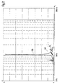
- FIG. 1 shows a side view of an inventive Player and Figure 2 shows a course of a Vibration amplitude over frequency.
- 10 indicates a player for storage disks 1.
- the storage disks for example to optical, magnetic, opto-magnetic storage disks 1 or the like.
- the playback device 10 can then be a compact disc player, a video disc player, or the like.
- the playback device 10 comprises a drive motor 2 which is fastened to a sheet metal 3 of a base support.
- the motor 2 drives an axis 55.
- a second circular plate 4 is mounted on the axis 55 and has an annular projection 60 concentric with the second plate 4, which engages in a circular opening 65 of the storage plate 1.
- the storage disk 1 is also circular, with a center 35 of the storage disk 1 being the center of the opening 65 at the same time.
- the storage plate 1 is centered on the second plate 4 by the projection 60 and concentric to the second plate 4.
- the projection 60 has an annular recess 70, which is also concentric with the second plate 4.
- the first plate 6 is also circular.
- a locking force F S is exerted approximately centrally on the first plate 6 approximately perpendicular to the plane of the plate, so that the storage plate 1 is clamped between the first plate 6 and the second plate 4 by the locking force F S.
- the first plate 6 has a second annular highlight 80 on a surface 85 facing the storage plate 1.
- the second annular highlight 80 of the first plate 6 is concentric with the first annular highlight 75 of the first plate 6.
- the second annular highlight 80 of the first plate 6 has a larger radius than the first annular highlight 75 of the first plate 6. In this way, the second annular highlight 80 of the first plate 6 rests on the storage plate 1.
- the second plate 4 comprises, on a surface 95 facing the storage plate 1, an annular projection 90 which is concentric with the projection 60 and has a larger radius than the projection 60.
- the storage disk 1 thus lies on the highlight 90 of the second disk 4.
- the radius of the second highlight 80 of the first plate 6 and the radius of the highlight 90 of the second plate 4 are approximately the same, so that the locking force F S is distributed along a circular ring concentric to the second plate 4 on the second plate 4.
- the locking force F S is, for example, between 1 and 2N.
- the read head On the plate 3 of the base support there are also an optical one Read head and a mechanism for guiding and transport arranged of the read head, but not shown in Figure 1.
- the read head probes for tracks using one the disk 1 focused light beam in the tracks recorded information. For this, the storage disk 1 via the axis 55 by the drive motor 2 in rotation added.
- the diameter of the second plate 4 is in this embodiment about 30 mm and corresponds approximately to that Diameter of the annular highlight 90 of the second Plate 4.
- storage disks 1 inserted into the player 10 behave like vibrators when the player 10, which can be integrated, for example, into a car radio, experiences vibrations according to an acceleration spectrum that are transmitted to its housing.
- the axial force F S which acts centrally on the first plate 6, suppresses any axial play in the area of the axis 55 arranged in the common center of the two plates 4, 6 and the storage plate 1.
- the amplitude of the described relative movement of the storage disk 1 is maximum when the drive motor 2 experiences an acceleration with a frequency that corresponds to the natural frequency of the storage disk 1 and the locking system.
- the storage disk 1 is then excited at its resonance frequency and the relative movement of the storage disk 1 takes on very large amplitudes when the damping of the storage disk 1 and its assembly is weak.
- the lens of the optical read head is controlled by a position control and thus follows the movements the disk 1.
- the inventors have found that with a typical acceleration spectrum, that is due to shocks the player 10 in about the vertical direction Plate level of the two plates 4, 6 and the storage plate 1 results in a position error in the regulation of Focusing the light beam of the optical reading head on a trace of the disk 1 as the main cause of the relative movement the disk 1 at its resonant frequency Has. It was found that the maximum allowable acceleration, in which there is still no interference with the scanning of the Traces of the disk 1 occur at the resonance frequency disk 1 is the lowest.
- An outer diameter 50 of the second annular highlight 80 of the first plate 6 corresponds approximately to the diameter the second plate 4, the annular highlighting 90 of the second plate 4 on an outer edge of the second plate 4 runs.
- a total diameter of 45 first plate 6 is larger than the outer diameter 50 of the second annular highlight 80 of the first plate 6 and less than or equal to an overall diameter of the storage disk 1.
- the distance 20 can be, for example be a few tenths of a millimeter.
- the one in the ring-shaped area 15 existing air forms a Air layer, the vibration of the disk 1 about perpendicular to the plane of the plate, especially at the resonance frequency the disk 1 dampens these vibrations.
- a essential non-elastic material with pores be arranged in a part of the annular disc-shaped area 15 or in the entire annular disc-shaped area 15 . It can be a textile or Act layer of felt, which due to the pores also air contains and thus to dampen the described Vibrations of the disk 1 contributes. This damping is further improved by the inelasticity of the material. Due to the air layer in the annular disk-shaped area 15 and the vibration of the disk 1 about Volume change of the ring-shaped area 15, these vibrations the disk 1 damped approximately perpendicular to the disk plane. By changing the dimensions of the washer-shaped Area 15 can have different damping can be set.
- the dimensions of the washer-shaped Area 15 can thereby be changed, for example be that with a constant outer diameter 50 of second annular highlight 80 of the first plate 6 of the Overall diameter 45 of the first plate 6 and / or the distance 20 between the first disk 6 and the storage disk 1 can be varied. With corresponding tests it was found that adequate vibration damping the disk 1 is reached when the total diameter 45 of the first plate 6 is chosen to be larger than 50 mm.
- FIG. 2 shows a course of an amplitude A of the relative movement of the storage disk 1 between its center 35 and its outer edge 30 as a function of the frequency f.
- the drive motor 2 was subjected to a sinusoidal movement approximately vertically to the plane of the disk 1, the frequency of which was changed between 20 Hz and 2000 Hz.
- An acceleration that occurs during movement 2 was set constant.
- an acceleration of 2 4m / s 2 selected.
- the storage disk 1 deforms approximately perpendicular to the disk plane of the storage disk 1, the resulting relative movement between the outer edge 30 of the storage disk 1 and a circular ring of the storage disk 1 in the region of the second annular highlighting 80 of the first disk 6 as representative of the center 35 was measured.
- the amplitude A of this relative movement is due to the constant acceleration 2 normalized in Figure 2 plotted against the frequency f. It is identified there by the reference numeral 25 and lies below a predetermined amplitude value 40 over the entire frequency range under consideration.
- the total diameter 45 of the first plate 6 was 60 mm, for the outer diameter 50 of the second annular highlighting 80 of the first plate 6 30 mm and a value of 0.1 mm is chosen for the distance 20 between the first plate 6 and the storage plate 1.
- the Philips test plate with the designation "SBC 444" was used as the storage plate 1 for the measurements. 2N were set as the locking force F S.
- the maximum amplitude of the vibrations was 40 ⁇ m for the relative movement.
- the outer diameter 50 of the second annular Emphasis 80 of the first plate 6 and the distance 20 between the first disk 6 and the storage disk 1 can damping through the air layer in this annular disk-shaped area 15 can be adjusted so that at approximately perpendicular to the plane of the plates 4, 6 and Storage disk 1 occurring vibrations of the player 10 with a not above a predetermined value lying acceleration an amplitude of the resulting Vibration of the outer edge 30 of the disk 1 in relation to the center 35 or to one in the area of second highlighting 80 of the first plate 6 Circular ring of the disk 1 or another point or Area of the disk 1, preferably in the vicinity thereof Center 35, is below a predetermined value.
- the total diameter 45 of the first Plate 6 exceeds a predetermined value in the described embodiment is 30 mm and the Outer diameter 50 of the second annular highlight 80 corresponds to the first plate 6. That way exceeds also the inner diameter of the washer-shaped Area 15 the outer diameter 50 of the second annular Emphasis 80 of the first plate 6 as given Value.
- a distance 20 between the first plate 6 and the Storage plate 1 in the annular disc-shaped area 15 can also 0 mm can be set, with such Distance 20 in the vibration of the disk 1 about perpendicular to the plane of the disk 1 nevertheless changing volume with an air layer between the first disk 6 and the disk 1 sets and as Damping agent is used. With otherwise selected parameters this results in a damping of the amplitude of the relative movement, which are of the same order of magnitude as the Choice of a distance 20 of 0.1 mm.
- the distance 20 remains in the entire annular disk-shaped area 15 approximately constant and the disk 1 does not get there in contact with the first plate 6.
- the Storage disk 1 in an edge region 105 of the first disk 6 only deformed by a few ⁇ m, since the deformations with fourth power of the radius increase towards the outside of the plate and thus 16 times smaller at the edge area 105, about 30 mm from the center 35 of the disk 1 away than at Outer edge 30 of the disk 1 are when the total diameter the disk 1 about twice as large is the total diameter 45 of the first plate 6.
- one metallized surface of the storage plate 1 covering can be placed under the first plate 6 at least in a part of the annular disk-shaped area 15 an essentially inelastic and with pores Material, for example in the form of a thin felt be glued.
- This material can also cover the entire the surface 85 of the first facing the storage disk 1 Cover plate 6 within the ring-shaped area 15.
- the material can also be provided only in part of the annular disk-shaped area 15 the surface 85 of the first facing the storage disk 1 Glue plate 6. This part can also be ring-shaped and be concentric with the second plate 4.
- So can for example an annular felt material with a Inner diameter of 57 mm and the total diameter 45 of the first plate 6 corresponding outer diameter of 60 mm on the surface 85 facing the storage disk 1 the first plate 6 is glued concentrically to the second plate 4 become.
- the thickness of the material can be chosen in this way be that the surface facing the first plate 6 the disk 1 also touches.
- the damping of the Amplitude of the relative movement of the disk 1 is included Using an essentially inelastic and with pores provided material at least in part of the annular disc Area 15 in the same order of magnitude as without using such a material in the form of an annular disk Area 15, the damping of the vibrations this relative movement even when using the essentially inelastic and porous material in the annular disk-shaped area 15 by the change in volume between the first disk 6 and the disk 1 and between the material and that facing the first plate 6 Surface of the disk 1 and that in the material even existing air layer is caused.
Landscapes
- Holding Or Fastening Of Disk On Rotational Shaft (AREA)
- Automatic Disk Changers (AREA)
Description
Claims (5)
- Abspielgerät (10) für eine Speicherplatte (1) mit einer ersten Platte (6) und einer zweiten Platte (4), wobei die Speicherplatte (1) zwischen der ersten Platte (6) und der zweiten Platte (4) einspannbar ist und zwischen der Speicherplatte (1) und der ersten Platte (6) innerhalb eines Bereiches (15) ein Abstand (20) vorgesehen ist, dadurch gekennzeichnet, daß der Bereich (15) durch entsprechende Dimensionierung der ersten Platte und der Abstand (20) so einstellbar sind, daß sich bei etwa senkrecht zu den Plattenebenen auftretenden Erschütterungen des Abspielgerätes (10) mit einer nicht über einem vorgegebenen Wert liegenden Beschleunigung eine Amplitude (25) einer sich ergebenden Schwingung eines Außenrandes (30) der Speicherplatte (1) im Verhältnis zu einem Mittelpunkt (35) der Speicherplatte (1) ergibt, die unterhalb eines vorgegebenen Wertes (40) liegt.
- Abspielgerät (10) nach Anspruch 1, dadurch gekennzeichnet, daß die erste und die zweite Platte (6, 4) jeweils kreisförmig ausgebildet sind und daß der Durchmesser (45) der ersten Platte (6) einen vorgegebenen Wert (50) überschreitet.
- Abspielgerät (10) nach Anspruch 2, dadurch gekennzeichnet, daß der Bereich (15) ringförmig ausgebildet ist und daß der Innendurchmesser des Bereiches (15) den vorgegebenen Wert (50) überschreitet.
- Abspielgerät (10) nach Anspruch 1, 2 oder 3, dadurch gekennzeichnet, daß zwischen der Speicherplatte (1) und der ersten Platte (6) zumindest in einem Teil des vorgegebenen Bereiches (15) ein im wesentlichen unelastisches und mit Poren versehenes Material angeordnet ist.
- Abspielgerät (10) nach Anspruch 4, dadurch gekennzeichnet, daß das Material als Filz oder Textil ausgebildet ist.
Applications Claiming Priority (3)
| Application Number | Priority Date | Filing Date | Title |
|---|---|---|---|
| DE19815492 | 1998-04-07 | ||
| DE19815492A DE19815492A1 (de) | 1998-04-07 | 1998-04-07 | Abspielgerät |
| PCT/DE1999/001032 WO1999052108A1 (de) | 1998-04-07 | 1999-04-06 | Abspielgerät |
Publications (2)
| Publication Number | Publication Date |
|---|---|
| EP1068614A1 EP1068614A1 (de) | 2001-01-17 |
| EP1068614B1 true EP1068614B1 (de) | 2002-09-11 |
Family
ID=7863837
Family Applications (1)
| Application Number | Title | Priority Date | Filing Date |
|---|---|---|---|
| EP99924780A Expired - Lifetime EP1068614B1 (de) | 1998-04-07 | 1999-04-06 | Abspielgerät |
Country Status (6)
| Country | Link |
|---|---|
| US (1) | US6469976B1 (de) |
| EP (1) | EP1068614B1 (de) |
| JP (1) | JP2003527717A (de) |
| DE (2) | DE19815492A1 (de) |
| HU (1) | HUP0101989A3 (de) |
| WO (1) | WO1999052108A1 (de) |
Families Citing this family (1)
| Publication number | Priority date | Publication date | Assignee | Title |
|---|---|---|---|---|
| KR100421054B1 (ko) * | 2002-03-25 | 2004-03-04 | 삼성전자주식회사 | 디스크 진동 저감 수단이 구비된 하드 디스크 드라이브 |
Family Cites Families (7)
| Publication number | Priority date | Publication date | Assignee | Title |
|---|---|---|---|---|
| FR2534405A1 (fr) | 1982-10-06 | 1984-04-13 | Hariton Bernard | Dispositif et procede de maintien, par depression, d'un disque sur un plateau tourne-disques |
| US4641152A (en) | 1986-02-24 | 1987-02-03 | Producers Color Service, Inc. | Fixturing apparatus for vibration dampened optical disc recording |
| NL8700819A (nl) | 1987-04-08 | 1988-11-01 | Philips Nv | Inrichting voor het registreren van informatie op of het uitlezen van informatie uit een informatieplaat. |
| JPS63259862A (ja) | 1987-04-16 | 1988-10-26 | Pioneer Electronic Corp | デイスク・クランプ装置 |
| EP0632441B1 (de) | 1993-06-14 | 2002-11-27 | Kabushiki Kaisha Kenwood | Haltevorrichtung für zwei Arten von optischen Platten |
| JPH08106692A (ja) | 1994-05-19 | 1996-04-23 | Pioneer Electron Corp | 両面ディスクのセンタリング機構 |
| DE19642343C2 (de) | 1996-10-14 | 1999-06-10 | Bosch Gmbh Robert | Verfahren zum Regeln der Fokussierung und der Führung eines Lichtstrahls |
-
1998
- 1998-04-07 DE DE19815492A patent/DE19815492A1/de not_active Withdrawn
-
1999
- 1999-04-06 EP EP99924780A patent/EP1068614B1/de not_active Expired - Lifetime
- 1999-04-06 US US09/673,064 patent/US6469976B1/en not_active Expired - Fee Related
- 1999-04-06 HU HU0101989A patent/HUP0101989A3/hu unknown
- 1999-04-06 WO PCT/DE1999/001032 patent/WO1999052108A1/de not_active Ceased
- 1999-04-06 DE DE59902656T patent/DE59902656D1/de not_active Expired - Fee Related
- 1999-04-06 JP JP2000542771A patent/JP2003527717A/ja active Pending
Also Published As
| Publication number | Publication date |
|---|---|
| DE59902656D1 (de) | 2002-10-17 |
| HUP0101989A2 (hu) | 2001-09-28 |
| HUP0101989A3 (en) | 2002-12-28 |
| EP1068614A1 (de) | 2001-01-17 |
| US6469976B1 (en) | 2002-10-22 |
| JP2003527717A (ja) | 2003-09-16 |
| WO1999052108A1 (de) | 1999-10-14 |
| DE19815492A1 (de) | 1999-10-14 |
Similar Documents
| Publication | Publication Date | Title |
|---|---|---|
| DE19536172C2 (de) | Vorrichtung zum Tragen eines optischen Aufnehmers | |
| DE69623736T2 (de) | Drehendes Gerät zur Datenaufnahme und -wiedergabe | |
| DE69736640T2 (de) | Plattenantriebsvorrichtung und Verfahren zur Einstellung ihrer Drehgeschwindigkeit | |
| DE2918919C2 (de) | ||
| DE69729358T2 (de) | CD-Laufwerk | |
| DE69228371T2 (de) | Optisches Plattengerät mit reduzierter Abmessung | |
| DE69811958T2 (de) | Wiederbeschreibbare optische datenspeicherplatte mit verbessenter planheit | |
| CH656736A5 (de) | Aufzeichnungs- und/oder wiedergabegeraet fuer eine flexible magnetscheibe. | |
| DE69728103T2 (de) | Selbstkompensierende dynamische Auswuchtvorrichtung für Plattenspieler | |
| DE3789099T2 (de) | Steuerungsgerät für Objektivlinse. | |
| CH622641A5 (de) | ||
| DE3627451A1 (de) | Dynamische daempfungseinrichtung fuer plattenlaufwerke | |
| DE3884844T2 (de) | Plattenklemmvorrichtung. | |
| DE3788930T2 (de) | Montage von magnetischen Köpfen. | |
| DE3609055C2 (de) | ||
| EP0962361A2 (de) | Elektronisches Gerät mit einer erschütterungsempfindlichen Baueinheit | |
| EP0221097B1 (de) | Elastische lagerung mit einstellbarer dämpfung für schallplattenspieler | |
| DE3889523T2 (de) | Optisches Gerät. | |
| DE4446902C2 (de) | Befestigungseinrichtung für einen Spindelmotor in einem Festplattenlaufwerk | |
| DE19642343C2 (de) | Verfahren zum Regeln der Fokussierung und der Führung eines Lichtstrahls | |
| EP1068614B1 (de) | Abspielgerät | |
| DE3839708C2 (de) | Disk-Abspielgerät mit einer Schwingungen absorbierenden Einrichtung | |
| EP0134428B1 (de) | Lesevorrichtung zum optischen Abtasten von auf einem bewegten plattenförmigen Träger aufgezeichneten Informationen | |
| DE3240734C2 (de) | Lichtabtastvorrichtung | |
| DE60205178T2 (de) | Schwingungsdämpfender Mechanismus |
Legal Events
| Date | Code | Title | Description |
|---|---|---|---|
| PUAI | Public reference made under article 153(3) epc to a published international application that has entered the european phase |
Free format text: ORIGINAL CODE: 0009012 |
|
| 17P | Request for examination filed |
Effective date: 20001107 |
|
| AK | Designated contracting states |
Kind code of ref document: A1 Designated state(s): CH DE FR GB IT LI |
|
| 17Q | First examination report despatched |
Effective date: 20010130 |
|
| GRAG | Despatch of communication of intention to grant |
Free format text: ORIGINAL CODE: EPIDOS AGRA |
|
| GRAG | Despatch of communication of intention to grant |
Free format text: ORIGINAL CODE: EPIDOS AGRA |
|
| GRAG | Despatch of communication of intention to grant |
Free format text: ORIGINAL CODE: EPIDOS AGRA |
|
| GRAH | Despatch of communication of intention to grant a patent |
Free format text: ORIGINAL CODE: EPIDOS IGRA |
|
| GRAH | Despatch of communication of intention to grant a patent |
Free format text: ORIGINAL CODE: EPIDOS IGRA |
|
| GRAA | (expected) grant |
Free format text: ORIGINAL CODE: 0009210 |
|
| AK | Designated contracting states |
Kind code of ref document: B1 Designated state(s): CH DE FR GB IT LI |
|
| REG | Reference to a national code |
Ref country code: GB Ref legal event code: FG4D Free format text: NOT ENGLISH |
|
| REG | Reference to a national code |
Ref country code: CH Ref legal event code: NV Representative=s name: SCINTILLA AG, DIREKTION Ref country code: CH Ref legal event code: EP |
|
| REF | Corresponds to: |
Ref document number: 59902656 Country of ref document: DE Date of ref document: 20021017 |
|
| GBT | Gb: translation of ep patent filed (gb section 77(6)(a)/1977) |
Effective date: 20030113 |
|
| ET | Fr: translation filed | ||
| PLBE | No opposition filed within time limit |
Free format text: ORIGINAL CODE: 0009261 |
|
| STAA | Information on the status of an ep patent application or granted ep patent |
Free format text: STATUS: NO OPPOSITION FILED WITHIN TIME LIMIT |
|
| 26N | No opposition filed |
Effective date: 20030612 |
|
| PGFP | Annual fee paid to national office [announced via postgrant information from national office to epo] |
Ref country code: IT Payment date: 20090428 Year of fee payment: 11 Ref country code: FR Payment date: 20090420 Year of fee payment: 11 |
|
| PGFP | Annual fee paid to national office [announced via postgrant information from national office to epo] |
Ref country code: CH Payment date: 20090427 Year of fee payment: 11 |
|
| PGFP | Annual fee paid to national office [announced via postgrant information from national office to epo] |
Ref country code: GB Payment date: 20090424 Year of fee payment: 11 Ref country code: DE Payment date: 20090624 Year of fee payment: 11 |
|
| REG | Reference to a national code |
Ref country code: CH Ref legal event code: PL |
|
| GBPC | Gb: european patent ceased through non-payment of renewal fee |
Effective date: 20100406 |
|
| REG | Reference to a national code |
Ref country code: FR Ref legal event code: ST Effective date: 20101230 |
|
| PG25 | Lapsed in a contracting state [announced via postgrant information from national office to epo] |
Ref country code: LI Free format text: LAPSE BECAUSE OF NON-PAYMENT OF DUE FEES Effective date: 20100430 Ref country code: DE Free format text: LAPSE BECAUSE OF NON-PAYMENT OF DUE FEES Effective date: 20101103 Ref country code: CH Free format text: LAPSE BECAUSE OF NON-PAYMENT OF DUE FEES Effective date: 20100430 |
|
| PG25 | Lapsed in a contracting state [announced via postgrant information from national office to epo] |
Ref country code: GB Free format text: LAPSE BECAUSE OF NON-PAYMENT OF DUE FEES Effective date: 20100406 Ref country code: IT Free format text: LAPSE BECAUSE OF NON-PAYMENT OF DUE FEES Effective date: 20100406 |
|
| PG25 | Lapsed in a contracting state [announced via postgrant information from national office to epo] |
Ref country code: FR Free format text: LAPSE BECAUSE OF NON-PAYMENT OF DUE FEES Effective date: 20100430 |