EP1068614B1 - Playback device - Google Patents
Playback device Download PDFInfo
- Publication number
- EP1068614B1 EP1068614B1 EP99924780A EP99924780A EP1068614B1 EP 1068614 B1 EP1068614 B1 EP 1068614B1 EP 99924780 A EP99924780 A EP 99924780A EP 99924780 A EP99924780 A EP 99924780A EP 1068614 B1 EP1068614 B1 EP 1068614B1
- Authority
- EP
- European Patent Office
- Prior art keywords
- plate
- disk
- storage
- annular
- playback device
- Prior art date
- Legal status (The legal status is an assumption and is not a legal conclusion. Google has not performed a legal analysis and makes no representation as to the accuracy of the status listed.)
- Expired - Lifetime
Links
- 239000000463 material Substances 0.000 claims description 19
- 230000001133 acceleration Effects 0.000 claims description 12
- 239000011148 porous material Substances 0.000 claims description 9
- 239000004753 textile Substances 0.000 claims description 3
- 230000010355 oscillation Effects 0.000 claims 1
- 238000013016 damping Methods 0.000 description 21
- 239000010410 layer Substances 0.000 description 9
- 230000003287 optical effect Effects 0.000 description 7
- 230000008901 benefit Effects 0.000 description 5
- 230000008859 change Effects 0.000 description 4
- 239000003795 chemical substances by application Substances 0.000 description 3
- 238000005259 measurement Methods 0.000 description 2
- 239000011241 protective layer Substances 0.000 description 2
- 230000009467 reduction Effects 0.000 description 2
- 230000004044 response Effects 0.000 description 2
- 238000006748 scratching Methods 0.000 description 2
- 230000002393 scratching effect Effects 0.000 description 2
- 238000001228 spectrum Methods 0.000 description 2
- 238000011161 development Methods 0.000 description 1
- 230000018109 developmental process Effects 0.000 description 1
- 239000013013 elastic material Substances 0.000 description 1
- 239000003292 glue Substances 0.000 description 1
- 238000007373 indentation Methods 0.000 description 1
- 230000007774 longterm Effects 0.000 description 1
- 230000007246 mechanism Effects 0.000 description 1
- 239000002184 metal Substances 0.000 description 1
- 238000000034 method Methods 0.000 description 1
- 230000008569 process Effects 0.000 description 1
- 239000000523 sample Substances 0.000 description 1
- 230000035945 sensitivity Effects 0.000 description 1
- 230000035939 shock Effects 0.000 description 1
- 239000000725 suspension Substances 0.000 description 1
Images

Classifications
-
- G—PHYSICS
- G11—INFORMATION STORAGE
- G11B—INFORMATION STORAGE BASED ON RELATIVE MOVEMENT BETWEEN RECORD CARRIER AND TRANSDUCER
- G11B17/00—Guiding record carriers not specifically of filamentary or web form, or of supports therefor
- G11B17/02—Details
- G11B17/022—Positioning or locking of single discs
- G11B17/028—Positioning or locking of single discs of discs rotating during transducing operation
- G11B17/0282—Positioning or locking of single discs of discs rotating during transducing operation by means provided on the turntable
-
- G—PHYSICS
- G11—INFORMATION STORAGE
- G11B—INFORMATION STORAGE BASED ON RELATIVE MOVEMENT BETWEEN RECORD CARRIER AND TRANSDUCER
- G11B17/00—Guiding record carriers not specifically of filamentary or web form, or of supports therefor
- G11B17/02—Details
- G11B17/022—Positioning or locking of single discs
- G11B17/028—Positioning or locking of single discs of discs rotating during transducing operation
- G11B17/0284—Positioning or locking of single discs of discs rotating during transducing operation by clampers
-
- G—PHYSICS
- G11—INFORMATION STORAGE
- G11B—INFORMATION STORAGE BASED ON RELATIVE MOVEMENT BETWEEN RECORD CARRIER AND TRANSDUCER
- G11B19/00—Driving, starting, stopping record carriers not specifically of filamentary or web form, or of supports therefor; Control thereof; Control of operating function ; Driving both disc and head
- G11B19/20—Driving; Starting; Stopping; Control thereof
- G11B19/2009—Turntables, hubs and motors for disk drives; Mounting of motors in the drive
- G11B19/2018—Incorporating means for passive damping of vibration, either in the turntable, motor or mounting
-
- G—PHYSICS
- G11—INFORMATION STORAGE
- G11B—INFORMATION STORAGE BASED ON RELATIVE MOVEMENT BETWEEN RECORD CARRIER AND TRANSDUCER
- G11B33/00—Constructional parts, details or accessories not provided for in the other groups of this subclass
- G11B33/02—Cabinets; Cases; Stands; Disposition of apparatus therein or thereon
- G11B33/08—Insulation or absorption of undesired vibrations or sounds
Definitions
- the invention relates to a player of the type of the main claim.
- US-A-4 641 152 discloses a player according to the preamble of Main claim 1.
- the player of the invention with the features of The main claim has the advantage that between the disk and the first disk within one a predetermined distance is provided and that the range and distance are selected so that in the event of vibrations occurring approximately perpendicular to the plate levels the player with one not over one acceleration given a value an amplitude a resulting vibration of an outer edge of the Disk in relation to a center of the Storage disk results below a given one Value.
- This way through the air layer between the storage disk and the first disk in the predetermined Area and by the volume change between the Disk and the first disk in the specified area when the disk vibrates, especially at the resonance frequency the disk the vibration of the Storage disk can be steamed without additional Damping agents are required.
- the air layer between the storage disk and the first disk in the given one Area and the volume change between the disk and the first plate in the predetermined area at the Vibration of the storage disk thus acts as a damping means.
- Another advantage is that position errors at focusing tracks of an optical disc by a light beam from a reading device for scanning of the information stored in the tracks at vertical vibrations of the storage disk occurring at the disk level can be largely suppressed, so that the reading device is very resistant to vibrations the player perpendicular to the disc plane is. This is particularly advantageous when using a Compact disc player trained player, the one Suspension of a disk drive without additional Has damping agents.
- Another advantage is that by damping the vibrations of the disk vertically to the disk plane the inertial forces that occur when the player is shaken transferred to the housing of the player will be greatly reduced.
- Another advantage is that by damping the vibrations of the disk vertically to the disk plane one for clamping the disk between the first and the second plate required locking force, those for fixing the storage disk to the second disk serves, is reduced.
- Vibrations of the storage disk By damping those that occur vertically to the plate level Vibrations of the storage disk can cause the storage disk So fix with a lower locking force while reducing their sensitivity to Vibrations of the player. If the second plate and with it through the storage disk and the first disk an axis driven by a motor during operation for Reading data is set in rotation, so the Motor and its bearings due to the locking force for clamping the disk between the first disk and the second plate less stressed, so its lifespan extended and the quality of the selection process long-term is maintained.
- FIG. 1 shows a side view of an inventive Player and Figure 2 shows a course of a Vibration amplitude over frequency.
- 10 indicates a player for storage disks 1.
- the storage disks for example to optical, magnetic, opto-magnetic storage disks 1 or the like.
- the playback device 10 can then be a compact disc player, a video disc player, or the like.
- the playback device 10 comprises a drive motor 2 which is fastened to a sheet metal 3 of a base support.
- the motor 2 drives an axis 55.
- a second circular plate 4 is mounted on the axis 55 and has an annular projection 60 concentric with the second plate 4, which engages in a circular opening 65 of the storage plate 1.
- the storage disk 1 is also circular, with a center 35 of the storage disk 1 being the center of the opening 65 at the same time.
- the storage plate 1 is centered on the second plate 4 by the projection 60 and concentric to the second plate 4.
- the projection 60 has an annular recess 70, which is also concentric with the second plate 4.
- the first plate 6 is also circular.
- a locking force F S is exerted approximately centrally on the first plate 6 approximately perpendicular to the plane of the plate, so that the storage plate 1 is clamped between the first plate 6 and the second plate 4 by the locking force F S.
- the first plate 6 has a second annular highlight 80 on a surface 85 facing the storage plate 1.
- the second annular highlight 80 of the first plate 6 is concentric with the first annular highlight 75 of the first plate 6.
- the second annular highlight 80 of the first plate 6 has a larger radius than the first annular highlight 75 of the first plate 6. In this way, the second annular highlight 80 of the first plate 6 rests on the storage plate 1.
- the second plate 4 comprises, on a surface 95 facing the storage plate 1, an annular projection 90 which is concentric with the projection 60 and has a larger radius than the projection 60.
- the storage disk 1 thus lies on the highlight 90 of the second disk 4.
- the radius of the second highlight 80 of the first plate 6 and the radius of the highlight 90 of the second plate 4 are approximately the same, so that the locking force F S is distributed along a circular ring concentric to the second plate 4 on the second plate 4.
- the locking force F S is, for example, between 1 and 2N.
- the read head On the plate 3 of the base support there are also an optical one Read head and a mechanism for guiding and transport arranged of the read head, but not shown in Figure 1.
- the read head probes for tracks using one the disk 1 focused light beam in the tracks recorded information. For this, the storage disk 1 via the axis 55 by the drive motor 2 in rotation added.
- the diameter of the second plate 4 is in this embodiment about 30 mm and corresponds approximately to that Diameter of the annular highlight 90 of the second Plate 4.
- storage disks 1 inserted into the player 10 behave like vibrators when the player 10, which can be integrated, for example, into a car radio, experiences vibrations according to an acceleration spectrum that are transmitted to its housing.
- the axial force F S which acts centrally on the first plate 6, suppresses any axial play in the area of the axis 55 arranged in the common center of the two plates 4, 6 and the storage plate 1.
- the amplitude of the described relative movement of the storage disk 1 is maximum when the drive motor 2 experiences an acceleration with a frequency that corresponds to the natural frequency of the storage disk 1 and the locking system.
- the storage disk 1 is then excited at its resonance frequency and the relative movement of the storage disk 1 takes on very large amplitudes when the damping of the storage disk 1 and its assembly is weak.
- the lens of the optical read head is controlled by a position control and thus follows the movements the disk 1.
- the inventors have found that with a typical acceleration spectrum, that is due to shocks the player 10 in about the vertical direction Plate level of the two plates 4, 6 and the storage plate 1 results in a position error in the regulation of Focusing the light beam of the optical reading head on a trace of the disk 1 as the main cause of the relative movement the disk 1 at its resonant frequency Has. It was found that the maximum allowable acceleration, in which there is still no interference with the scanning of the Traces of the disk 1 occur at the resonance frequency disk 1 is the lowest.
- An outer diameter 50 of the second annular highlight 80 of the first plate 6 corresponds approximately to the diameter the second plate 4, the annular highlighting 90 of the second plate 4 on an outer edge of the second plate 4 runs.
- a total diameter of 45 first plate 6 is larger than the outer diameter 50 of the second annular highlight 80 of the first plate 6 and less than or equal to an overall diameter of the storage disk 1.
- the distance 20 can be, for example be a few tenths of a millimeter.
- the one in the ring-shaped area 15 existing air forms a Air layer, the vibration of the disk 1 about perpendicular to the plane of the plate, especially at the resonance frequency the disk 1 dampens these vibrations.
- a essential non-elastic material with pores be arranged in a part of the annular disc-shaped area 15 or in the entire annular disc-shaped area 15 . It can be a textile or Act layer of felt, which due to the pores also air contains and thus to dampen the described Vibrations of the disk 1 contributes. This damping is further improved by the inelasticity of the material. Due to the air layer in the annular disk-shaped area 15 and the vibration of the disk 1 about Volume change of the ring-shaped area 15, these vibrations the disk 1 damped approximately perpendicular to the disk plane. By changing the dimensions of the washer-shaped Area 15 can have different damping can be set.
- the dimensions of the washer-shaped Area 15 can thereby be changed, for example be that with a constant outer diameter 50 of second annular highlight 80 of the first plate 6 of the Overall diameter 45 of the first plate 6 and / or the distance 20 between the first disk 6 and the storage disk 1 can be varied. With corresponding tests it was found that adequate vibration damping the disk 1 is reached when the total diameter 45 of the first plate 6 is chosen to be larger than 50 mm.
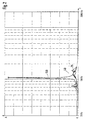
- FIG. 2 shows a course of an amplitude A of the relative movement of the storage disk 1 between its center 35 and its outer edge 30 as a function of the frequency f.
- the drive motor 2 was subjected to a sinusoidal movement approximately vertically to the plane of the disk 1, the frequency of which was changed between 20 Hz and 2000 Hz.
- An acceleration that occurs during movement 2 was set constant.
- an acceleration of 2 4m / s 2 selected.
- the storage disk 1 deforms approximately perpendicular to the disk plane of the storage disk 1, the resulting relative movement between the outer edge 30 of the storage disk 1 and a circular ring of the storage disk 1 in the region of the second annular highlighting 80 of the first disk 6 as representative of the center 35 was measured.
- the amplitude A of this relative movement is due to the constant acceleration 2 normalized in Figure 2 plotted against the frequency f. It is identified there by the reference numeral 25 and lies below a predetermined amplitude value 40 over the entire frequency range under consideration.
- the total diameter 45 of the first plate 6 was 60 mm, for the outer diameter 50 of the second annular highlighting 80 of the first plate 6 30 mm and a value of 0.1 mm is chosen for the distance 20 between the first plate 6 and the storage plate 1.
- the Philips test plate with the designation "SBC 444" was used as the storage plate 1 for the measurements. 2N were set as the locking force F S.
- the maximum amplitude of the vibrations was 40 ⁇ m for the relative movement.
- the outer diameter 50 of the second annular Emphasis 80 of the first plate 6 and the distance 20 between the first disk 6 and the storage disk 1 can damping through the air layer in this annular disk-shaped area 15 can be adjusted so that at approximately perpendicular to the plane of the plates 4, 6 and Storage disk 1 occurring vibrations of the player 10 with a not above a predetermined value lying acceleration an amplitude of the resulting Vibration of the outer edge 30 of the disk 1 in relation to the center 35 or to one in the area of second highlighting 80 of the first plate 6 Circular ring of the disk 1 or another point or Area of the disk 1, preferably in the vicinity thereof Center 35, is below a predetermined value.
- the total diameter 45 of the first Plate 6 exceeds a predetermined value in the described embodiment is 30 mm and the Outer diameter 50 of the second annular highlight 80 corresponds to the first plate 6. That way exceeds also the inner diameter of the washer-shaped Area 15 the outer diameter 50 of the second annular Emphasis 80 of the first plate 6 as given Value.
- a distance 20 between the first plate 6 and the Storage plate 1 in the annular disc-shaped area 15 can also 0 mm can be set, with such Distance 20 in the vibration of the disk 1 about perpendicular to the plane of the disk 1 nevertheless changing volume with an air layer between the first disk 6 and the disk 1 sets and as Damping agent is used. With otherwise selected parameters this results in a damping of the amplitude of the relative movement, which are of the same order of magnitude as the Choice of a distance 20 of 0.1 mm.
- the distance 20 remains in the entire annular disk-shaped area 15 approximately constant and the disk 1 does not get there in contact with the first plate 6.
- the Storage disk 1 in an edge region 105 of the first disk 6 only deformed by a few ⁇ m, since the deformations with fourth power of the radius increase towards the outside of the plate and thus 16 times smaller at the edge area 105, about 30 mm from the center 35 of the disk 1 away than at Outer edge 30 of the disk 1 are when the total diameter the disk 1 about twice as large is the total diameter 45 of the first plate 6.
- one metallized surface of the storage plate 1 covering can be placed under the first plate 6 at least in a part of the annular disk-shaped area 15 an essentially inelastic and with pores Material, for example in the form of a thin felt be glued.
- This material can also cover the entire the surface 85 of the first facing the storage disk 1 Cover plate 6 within the ring-shaped area 15.
- the material can also be provided only in part of the annular disk-shaped area 15 the surface 85 of the first facing the storage disk 1 Glue plate 6. This part can also be ring-shaped and be concentric with the second plate 4.
- So can for example an annular felt material with a Inner diameter of 57 mm and the total diameter 45 of the first plate 6 corresponding outer diameter of 60 mm on the surface 85 facing the storage disk 1 the first plate 6 is glued concentrically to the second plate 4 become.
- the thickness of the material can be chosen in this way be that the surface facing the first plate 6 the disk 1 also touches.
- the damping of the Amplitude of the relative movement of the disk 1 is included Using an essentially inelastic and with pores provided material at least in part of the annular disc Area 15 in the same order of magnitude as without using such a material in the form of an annular disk Area 15, the damping of the vibrations this relative movement even when using the essentially inelastic and porous material in the annular disk-shaped area 15 by the change in volume between the first disk 6 and the disk 1 and between the material and that facing the first plate 6 Surface of the disk 1 and that in the material even existing air layer is caused.
Landscapes
- Holding Or Fastening Of Disk On Rotational Shaft (AREA)
- Automatic Disk Changers (AREA)
Description
Die Erfindung geht von einem Abspielgerät nach der Gattung des Hauptanspruchs aus.The invention relates to a player of the type of the main claim.
Aus der noch nicht vorveröffentlichten deutschen Patentanmeldung
mit dem Aktenzeichen 1 96 42 343 ist bereits ein Abspielgerät
bekannt, bei dem ein Compact-Disc-Motor über eine
Achse einen als Compact-Disc ausgebildeten Aufzeichnungsträger
antreibt, der zwischen eine erste mit der Achse verbundene
Platte und eine zweite Platte eingespannt ist.From the as yet unpublished German patent application
with the
US-A-4 641 152 offenbart ein Abspielgerät gemäß des Oberbegriffes von
Hauptanspruch 1.US-A-4 641 152 discloses a player according to the preamble of
Das erfindungsgemäße Abspielgerät mit den Merkmalen des Hauptanspruchs hat demgegenüber den Vorteil, daß zwischen der Speicherplatte und der ersten Platte innerhalb eines vorgegebenen Bereiches ein vorgegebener Abstand vorgesehen ist und daß der Bereich und der Abstand so gewählt sind, daß bei etwa senkrecht zu den Plattenebenen auftretenden Erschütterungen des Abspielgerätes mit einer nicht über einem vorgegebenen Wert liegenden Beschleunigung eine Amplitude einer sich ergebenden Schwingung eines Außenrandes der Speicherplatte im Verhältnis zu einem Mittelpunkt der Speicherplatte ergibt, die unterhalb eines vorgegebenen Wertes liegt. Auf diese Weise kann durch die Luftschicht zwischen der Speicherplatte und der ersten Platte im vorgegebenen Bereich und durch die Volumenänderung zwischen der Speicherplatte und der ersten Platte im vorgegebenen Bereich bei der Schwingung der Speicherplatte, vor allem bei der Resonanzfrequenz der Speicherplatte die Schwingung der Speicherplatte gedämpft werden, ohne daß zusätzliche Dämpfungsmittel erforderlich sind. Die Luftschicht zwischen der Speicherplatte und der ersten Platte in dem vorgegebenen Bereich und die Volumenänderung zwischen der Speicherplatte und der ersten Platte in dem vorgegebenen Bereich bei der Schwingung der Speicherplatte wirken somit als Dämpfungsmittel.The player of the invention with the features of The main claim has the advantage that between the disk and the first disk within one a predetermined distance is provided and that the range and distance are selected so that in the event of vibrations occurring approximately perpendicular to the plate levels the player with one not over one acceleration given a value an amplitude a resulting vibration of an outer edge of the Disk in relation to a center of the Storage disk results below a given one Value. This way, through the air layer between the storage disk and the first disk in the predetermined Area and by the volume change between the Disk and the first disk in the specified area when the disk vibrates, especially at the resonance frequency the disk the vibration of the Storage disk can be steamed without additional Damping agents are required. The air layer between the storage disk and the first disk in the given one Area and the volume change between the disk and the first plate in the predetermined area at the Vibration of the storage disk thus acts as a damping means.
Ein weiterer Vorteil besteht darin, daß Positionsfehler bei der Fokussierung von Spuren einer optischen Speicherplatte durch einen Lichtstrahl einer Lesevorrichtung zur Abtastung der in den Spuren gespeicherten Informationen bei vertikal zur Plattenebene auftretenden Schwingungen der Speicherplatte in großem Umfang unterdrückt werden können, so daß die Lesevorrichtung sehr widerstandsfähig gegenüber Erschütterungen des Abspielgerätes senkrecht zu der Plattenebene ist. Dies ist besonders vorteilhaft bei einem als Compact-Disc-Spieler ausgebildeten Abspielgerät, das eine Aufhängung eines Plattenlaufwerks ohne zusätzliche Dämpfungsmittel aufweist. Another advantage is that position errors at focusing tracks of an optical disc by a light beam from a reading device for scanning of the information stored in the tracks at vertical vibrations of the storage disk occurring at the disk level can be largely suppressed, so that the reading device is very resistant to vibrations the player perpendicular to the disc plane is. This is particularly advantageous when using a Compact disc player trained player, the one Suspension of a disk drive without additional Has damping agents.
Ein weiterer Vorteil besteht darin, daß durch die Dämpfung der Schwingungen der Speicherplatte vertikal zur Plattenebene die Inertialkräfte, die bei Erschütterungen des Abspielgerätes auf das Gehäuse des Abspielgerätes übertragen werden, stark verringert werden.Another advantage is that by damping the vibrations of the disk vertically to the disk plane the inertial forces that occur when the player is shaken transferred to the housing of the player will be greatly reduced.
Ein weiterer Vorteil besteht darin, daß durch die Dämpfung der Schwingungen der Speicherplatte vertikal zur Plattenebene eine zum Einspannen der Speicherplatte zwischen die erste und die zweite Platte erforderliche Feststellkraft, die zur Fixierung der Speicherplatte auf der zweiten Platte dient, reduziert wird.Another advantage is that by damping the vibrations of the disk vertically to the disk plane one for clamping the disk between the first and the second plate required locking force, those for fixing the storage disk to the second disk serves, is reduced.
Durch die Dämpfung der vertikal zur Plattenebene auftretenden Schwingungen der Speicherplatte läßt sich die Speicherplatte also mit einer geringeren Feststellkraft fixieren bei gleichzeitiger Verringerung ihrer Empfindlichkeit gegenüber Erschütterungen des Abspielgerätes. Wenn die zweite Platte und mit ihr die Speicherplatte und die erste Platte durch eine von einem Motor angetriebene Achse beim Betrieb zum Auslesen von Daten in Rotation versetzt wird, so wird der Motor und seine Lager durch die Feststellkraft zum Einspannen der Speicherplatte zwischen die erste Platte und die zweite Platte weniger belastet, so daß seine Lebensdauer verlängert und die Qualität des Auslesevorgangs langfristig aufrechterhalten wird.By damping those that occur vertically to the plate level Vibrations of the storage disk can cause the storage disk So fix with a lower locking force while reducing their sensitivity to Vibrations of the player. If the second plate and with it through the storage disk and the first disk an axis driven by a motor during operation for Reading data is set in rotation, so the Motor and its bearings due to the locking force for clamping the disk between the first disk and the second plate less stressed, so its lifespan extended and the quality of the selection process long-term is maintained.
Durch die in den Unteransprüchen aufgeführten Maßnahmen sind vorteilhafte Weiterbildungen und Verbesserungen des im Hauptanspruch angegebenen Abspielgerätes möglich. By the measures listed in the subclaims advantageous further developments and improvements of the Main claim specified player possible.
Besonders vorteilhaft ist es, daß zwischen der Speicherplatte und der ersten Platte zumindest in einem Teil des vorgegebenen Bereiches ein im wesentlichen unelastisches und mit Poren versehenes Material angeordnet ist. Auf diese Weise wird verhindert, daß bei Schwingungen der Speicherplatte vertikal zur Plattenebene ein Zerkratzen einer eine beispielsweise metallisierte Oberfläche der Speicherplatte abdeckenden Schutzschicht durch wiederholtes Auftreffen der Speicherplatte auf der ersten Platte erfolgt. Eine Dämpfung der Schwingungen der Speicherplatte senkrecht zur Plattenebene ist dabei aufgrund der Poren des Materials möglich, die eine Luftschicht zwischen der Speicherplatte und der ersten Platte ermöglichen. Durch Verwendung eines unelastischen Materials wird die Dämpfung der Schwingungen der Speicherplatte vertikal zur Plattenebene weiter verbessert.It is particularly advantageous that between the storage disk and the first plate in at least part of the given range is essentially inelastic and material is provided with pores. To this This prevents the disk from vibrating a scratching one a vertical to the plate level for example, metallized surface of the storage disk covering protective layer by repeatedly hitting the Storage disk is done on the first disk. A damping the vibrations of the storage disk perpendicular to the disk plane is possible due to the pores of the material, which is an air layer between the disk and the enable first plate. By using an inelastic The damping of the vibrations of the material Storage disk vertical to disk level further improved.
Ein Ausführungsbeispiel der Erfindung ist in der Zeichnung dargestellt und in der nachfolgenden Beschreibung näher erläutert. Es zeigen Figur 1 eine Seitenansicht eines erfindungsgemäßen Abspielgerätes und Figur 2 einen Verlauf einer Schwingungsamplitude über der Frequenz.An embodiment of the invention is in the drawing shown and explained in more detail in the following description. 1 shows a side view of an inventive Player and Figure 2 shows a course of a Vibration amplitude over frequency.
In Figur 1 kennzeichnet 10 ein Abspielgerät für Speicherplatten
1. Bei den Speicherplatten 1 kann es sich beispielsweise
um optische, magnetische, opto-magnetische Speicherplatten
1 oder dergleichen handeln. In diesem Ausführungsbeispiel
wird ein Abspielgerät 10 zum Abspielen einer optischen
Speicherplatte 1, beispielsweise einer Compact-Disc,
einer digitalen Video-Disc oder dergleichen beschrieben. Das
Abspielgerät 10 kann dann entsprechend ein Compact-Disc-Spieler,
ein Video-Disc-Spieler, oder dergleichen sein.In Figure 1, 10 indicates a player for
Das Abspielgerät 10 umfaßt einen Antriebsmotor 2, der an
einem Blech 3 eines Grundträgers befestigt ist. Der Motor 2
treibt eine Achse 55 an. Auf die Achse 55 ist eine zweite
kreisförmig ausgebildete Platte 4 montiert, die einen ringförmigen
Vorsprung 60 konzentrisch zur zweiten Platte 4 aufweist,
der in einen kreisförmigen Durchbruch 65 der
Speicherplatte 1 eingreift. Die Speicherplatte 1 ist ebenfalls
kreisförmig ausgebildet, wobei ein Mittelpunkt 35 der
Speicherplatte 1 gleichzeitig der Mittelpunkt des Durchbruchs
65 ist. Die Speicherplatte 1 liegt auf der zweiten
Platte 4 zentriert durch den Vorsprung 60 und konzentrisch
zur zweiten Platte 4 auf. Der Vorsprung 60 weist eine ringförmige
Einbuchtung 70 auf, die ebenfalls konzentrisch zur
zweiten Platte 4 ist. In die ringförmige Einbuchtung 70
greift eine erste ringförmige Hervorhebung 75 einer ersten
Platte 6, die ebenfalls konzentrisch zur zweiten Platte 4
ist, ein. Die erste Platte 6 ist ebenfalls kreisförmig ausgebildet.
Durch ein in Figur 1 nicht dargestelltes Hebelsystem
wird eine Feststellkraft FS etwa senkrecht zur
Plattenebene auf die erste Platte 6 etwa mittig ausgeübt, so
daß die Speicherplatte 1 durch die Feststellkraft FS
zwischen die erste Platte 6 und die zweite Platte 4 eingespannt
wird. Durch den Eingriff der ersten Hervorhebung 75
in die Einbuchtung 70 ist die erste Platte 6 zentriert und
auf der zweiten Platte 4 fixiert. Die erste Platte 6 weist
eine zweite ringförmige Hervorhebung 80 an einer der
Speicherplatte 1 zugewandten Oberfläche 85 auf. Die zweite
ringförmige Hervorhebung 80 der ersten Platte 6 ist dabei
konzentrisch zur ersten ringförmigen Hervorhebung 75 der
ersten Platte 6. Die zweite ringförmige Hervorhebung 80 der
ersten Platte 6 weist jedoch einen größeren Radius als die
erste ringförmige Hervorhebung 75 der ersten Platte 6 auf.
Auf diese Weise liegt die zweite ringförmige Hervorhebung 80
der ersten Platte 6 auf der Seicherplatte 1 auf.The
Die zweite Platte 4 umfaßt an einer der Speicherplatte 1 zugewandten
Oberfläche 95 eine ringförmige Hervorhebung 90,
die zum Vorsprung 60 konzentrisch ist und einen größeren Radius
als der Vorsprung 60 aufweist. Die Speicherplatte 1
liegt somit auf der Hervorhebung 90 der zweiten Platte 4
auf. Der Radius der zweiten Hervorhebung 80 der ersten
Platte 6 und der Radius der Hervorhebung 90 der zweiten
Platte 4 sind etwa gleich, so daß sich die Feststellkraft FS
entlang eines zur zweiten Platte 4 konzentrischen Kreisrings
auf der zweiten Platte 4 verteilt. Es gibt jedoch auch Abspielgeräte,
bei denen die Feststellkraft FS in umgekehrter
Richtung auf die erste Platte 6 wirkt und dort entsprechend
auf einem Kreisring oder auch beispielsweise auf drei um
120° voneinander beabstandeten Punkten verteilt wirkt. Die
Feststellkraft FS liegt beispielsweise zwischen 1 und 2N.The
Auf dem Blech 3 des Grundträgers sind außerdem ein optischer
Lesekopf und ein Mechanismus zur Führung und zum Transport
des Lesekopfes angeordnet, in Figur 1 jedoch nicht dargestellt.
Der Lesekopf tastet dabei mittels eines auf Spuren
der Speicherplatte 1 fokussierten Lichtstrahls in den Spuren
aufgezeichnete Informationen ab. Dazu wird die Speicherplatte
1 über die Achse 55 durch den Antriebsmotor 2 in Rotation
versetzt. On the plate 3 of the base support there are also an optical one
Read head and a mechanism for guiding and transport
arranged of the read head, but not shown in Figure 1.
The read head probes for tracks using one
the
Der Durchmesser der zweiten Platte 4 beträgt in diesem Ausführungsbeispiel
etwa 30 mm und entspricht ungefähr dem
Durchmesser der ringförmigen Hervorhebung 90 der zweiten
Platte 4.The diameter of the
Wird das Abspielgerät 10 in einem Fahrzeug montiert, so verhalten
sich in das Abspielgerät 10 eingelegte Speicherplatten
1 wie Schwinger, wenn das Abspielgerät 10, das beispielsweise
in ein Autoradio integriert sein kann, Erschütterungen
gemäß eines Beschleunigungsspektrums erfährt,
die an sein Gehäuse übertragen werden. Durch die Feststellkraft
FS, die mittig auf die erste Platte 6 einwirkt, wird
jegliches axiale Spiel im Bereich der im gemeinsamen Mittelpunkt
der beiden Platten 4, 6 und der Speicherplatte 1 angeordneten
Achse 55 unterdrückt. Auf diese Weise ergibt sich
bei Einwirkung einer Vibration auf das Abspielgerät 10 in
axialer Richtung, d. h. etwa vertikal zur Plattenebene der
beiden Platten 4, 6 und der Speicherplatte 1, eine symmetrische
Deformation der Speicherplatte 1 bezüglich der Achse
55, wobei sich eine Relativbewegung eines Außenrandes 30 der
Speicherplatte 1 bezüglich dem Mittelpunkt 35 der Speicherplatte
1 ergibt. Die Amplitude dieser Bewegung hängt von der
Frequenz und der Amplitude der Beschleunigung des Antriebsmotors
2, dem Material und den Abmessungen der Speicherplatte
1 selbst und vom verwendeten Feststellsystem zur
zentrierten Einspannung der Speicherplatte 1 zwischen der
ersten Platte 6 und der zweiten Platte 4 ab. Die Beschleunigung
des Antriebsmotors 2 rührt dabei von Erschütterungen
des Abspielgerätes 10 im Fahrzeug her. Die
Amplitude der beschriebenen Relativbewegung der Speicherplatte
1 ist dabei maximal, wenn der Antriebsmotor 2 eine
Beschleunigung mit einer Frequenz erfährt, die der Eigenfrequenz
der Speicherplatte 1 und des Feststellsystems entspricht.
Die Speicherplatte 1 wird dann bei ihrer Resonanzfrequenz
angeregt und die Relativbewegung der Speicherplatte
1 nimmt sehr große Amplituden an, wenn die Dämpfung der
Speicherplatte 1 und ihrer Montage schwach ist. Um den eingestellten
Abstand zwischen einem Objektiv des optischen
Lesekopfes und der Speicherplatte 1 mit einer zum fehlerfreien
Auslesen der Spuren der Speicherplatte 1 erforderlichen
Genauigkeit von zur Zeit etwa ±2 µm einzuhalten, wird
das Objektiv des optischen Lesekopfes durch eine Positionsregelung
angesteuert und folgt somit den Bewegungen der
Speicherplatte 1.If the
Die Erfinder haben festgestellt, daß bei einem typischen Beschleunigungsspektrum,
das sich aufgrund von Erschütterungen
des Abspielgerätes 10 in etwa vertikaler Richtung zur
Plattenebene der beiden Platten 4, 6 und der Speicherplatte
1 ergibt, ein Positionsfehler bei der Regelung der
Fokussierung des Lichtstrahls des optischen Lesekopfes auf
eine Spur der Speicherplatte 1 als Hauptursache die Relativbewegung
der Speicherplatte 1 bei ihrer Resonanzfrequenz
hat. Es wurde festgestellt, daß die maximal zulässige Beschleunigung,
bei der noch keine Störungen der Abtastung der
Spuren der Speicherplatte 1 auftreten, bei der Resonanzfrequenz
der Speicherplatte 1 am geringsten ist.The inventors have found that with a typical acceleration spectrum,
that is due to shocks
the
Ein Außendurchmesser 50 der zweiten ringförmigen Hervorhebung
80 der ersten Platte 6 entspricht ungefähr dem Durchmesser
der zweiten Platte 4, wobei die ringförmige Hervorhebung
90 der zweiten Platte 4 an einem Außenrand der
zweiten Platte 4 verläuft. Ein Gesamtdurchmesser 45 der
ersten Platte 6 ist größer als der Außendurchmesser 50 der
zweiten ringförmigen Hervorhebung 80 der ersten Platte 6 und
kleiner oder gleich einem Gesamtdurchmesser der Speicherplatte
1.An outer diameter 50 of the second
Zwischen dem Außendurchmesser 50 der zweiten ringförmigen
Hervorhebung 80 der ersten Platte 6 und dem Gesamtdurchmesser
45 der ersten Platte 6 ist ein Abstand 20 zwischen
der ersten Platte 6 und der Speicherplatte 1 vorgesehen. Auf
diese Weise entsteht zwischen dem Außendurchmesser 50 der
zweiten ringförmigen Hervorhebung 80 der ersten Platte 6 und
dem Gesamtdurchmesser 45 der ersten Platte 6 ein konzentrisch
zur zweiten Platte 4 angeordneter ringscheibenförmiger
Bereich 15. Der Abstand 20 kann dabei beispielsweise
einige Zehntel Millimeter betragen. Die in dem
ringscheibenförmigen Bereich 15 vorhandene Luft bildet eine
Luftschicht, die bei Schwingung der Speicherplatte 1 etwa
senkrecht zur Plattenebene, vor allem bei der Resonanzfrequenz
der Speicherplatte 1 diese Schwingungen dämpft. In
einem Teil des ringscheibenförmigen Bereiches 15 oder auch
im gesamten ringscheibenförmigen Bereich 15 kann ein im
wesentlichen unelastisches und mit Poren versehenes Material
angeordnet sein. Dabei kann es sich um eine Textil- oder
Filzschicht handeln, die aufgrund der Poren ebenfalls Luft
enthält und somit zur Dämpfung der beschriebenen
Schwingungen der Speicherplatte 1 beiträgt. Diese Dämpfung
wird durch die Unelastizität des Materials noch verbessert.
Aufgrund der Luftschicht im ringscheibenförmigen Bereich 15
und der bei der Schwingung der Speicherplatte 1 etwa
senkrecht zur Plattenebene auftretenden Volumenänderung des
ringscheibenförmigen Bereiches 15 werden diese Schwingungen
der Speicherplatte 1 etwa senkrecht zur Plattenebene gedämpft.
Durch Veränderung der Abmessungen des ringscheibenförmigen
Bereiches 15 können unterschiedliche Dämpfungen
eingestellt werden. Die Abmessungen des ringscheibenförmigen
Bereiches 15 können dabei beispielsweise dadurch geändert
werden, daß bei gleichbleibendem Außendurchmesser 50 der
zweiten ringförmigen Hervorhebung 80 der ersten Platte 6 der
Gesamtdurchmesser 45 der ersten Platte 6 und/oder der Abstand
20 zwischen der ersten Platte 6 und der Speicherplatte
1 variiert werden. Bei entsprechenden Versuchen wurde festgestellt,
daß eine ausreichende Dämpfung der Schwingungen
der Speicherplatte 1 erreicht wird, wenn der Gesamtdurchmesser
45 der ersten Platte 6 größer als 50 mm gewählt wird.Between the outer diameter 50 of the second
Figur 2 zeigt einen Verlauf einer Amplitude A der Relativbewegung
der Speicherplatte 1 zwischen ihrem Mittelpunkt 35
und ihrem Außenrand 30 in Abhängigkeit der Frequenz f. Zur
Ermittlung des Frequenzgangs dieser Amplitude wurde der Antriebsmotor
2 etwa vertikal zur Plattenebene der Speicherplatte
1 einer sinusförmigen Bewegung unterworfen, deren
Frequenz zwischen 20 Hz und 2000 Hz verändert wurde. Eine
bei der Bewegung auftretende Beschleunigung ![]()
![]()
Die gleichen Messungen wurden auch mit einer ersten Platte 6
durchgeführt, deren Gesamtdurchmesser 45 etwa dem Außendurchmesser
50 der zweiten ringförmigen Hervorhebung 80 der
ersten Platte 6 entspricht, so daß sich kein dämpfender
ringscheibenförmiger Bereich 15 ergibt. Dabei ergibt sich
eine in Figur 2 durch das Bezugszeichen 100 gekennzeichnete
Amplitude der Relativbewegung zwischen dem Außenrand 30 der
Speicherplatte 1 und dem Kreisring der Speicherplatte 1, der
sich im Bereich der zweiten ringförmigen Hervorhebung 80 der
ersten Platte 6 befindet, wobei diese Amplitude 100 bei der
Resonanzfrequenz der Speicherplatte 1 von 106,8 Hz einen
Maximalwert von 487 µm erreicht. Bei anderen Speicherplatten
ergaben sich für Resonanzfrequenzwerte zwischen 85 Hz und
115 Hz Amplituden in der gleichen Größenordnung. Daraus ergibt
sich bei Verwendung des ringscheibenförmigen Bereiches
15 mit den beschriebenen Abmessungen von 60 mm für den Gesamtdurchmesser
45 der ersten Platte 6 und 0,1 mm für den
Abstand 20 zwischen der ersten Platte 6 und der Speicherplatte
1 eine Verringerung der Amplitude der Relativbewegung
um etwa den Faktor 12. Der gemäß Figur 2 beispielhaft vorgegebene
Wert 40 für die Amplitude A, der die obere Grenze für
die Amplitude der Relativbewegung sein und von der Amplitude
der Relativbewegung unterschritten werden soll, entspricht
etwa 70 µm.The same measurements were also made with a
Bei dem Gesamtdurchmesser 45 der ersten Platte 6 von 60 mm
und doppeltem Abstand 20 zwischen der ersten Platte 6 und
der Speicherplatte 1 von 0,2 mm ergibt sich eine maximale
Amplitude für die Relativbewegung, die gegenüber dem Maximum
der Amplitude 100 für die beschriebene Anordnung ohne
dämpfenden ringscheibenförmigen Bereich 15 lediglich eine
Verringerung um den Faktor 2,5 aufweist und damit eine Überschreitung
des vorgegebenen Amplitudenwertes 40 zur Folge
hat.With the total diameter 45 of the
Durch entsprechende Dimensionierung des ringscheibenförmigen
Bereiches 15 mittels der Wahl des Gesamtdurchmessers 45 der
ersten Platte 6, des Außendurchmessers 50 der zweiten ringförmigen
Hervorhebung 80 der ersten Platte 6 und des Abstandes
20 zwischen der ersten Platte 6 und der Speicherplatte
1 kann die Dämpfung durch die Luftschicht in diesem
ringscheibenförmigen Bereich 15 so eingestellt werden, daß
bei etwa senkrecht zur Plattenebene der Platten 4, 6 und der
Speicherplatte 1 auftretenden Erschütterungen des Abspielgerätes
10 mit einer nicht über einem vorgegebenen Wert
liegenden Beschleunigung eine Amplitude der sich ergebenden
Schwingung des Außenrandes 30 der Speicherplatte 1 im Verhältnis
zum Mittelpunkt 35 oder zu einem im Bereich der
zweiten Hervorhebung 80 der ersten Platte 6 befindlichen
Kreisring der Speicherplatte 1 oder einem anderen Punkt oder
Bereich der Speicherplatte 1, vorzugsweise in der Nähe deren
Mittelpunktes 35, unterhalb eines vorgegebenen Wertes liegt. By appropriate dimensioning of the
Zur Realisierung des ringscheibenförmigen Bereiches 15 ist
es erforderlich, daß der Gesamtdurchmesser 45 der ersten
Platte 6 einen vorgegebenen Wert überschreitet, der in dem
beschriebenen Ausführungsbeispiel 30 mm beträgt und dem
Außendurchmesser 50 der zweiten ringförmigen Hervorhebung 80
der ersten Platte 6 entspricht. Auf diese Weise überschreitet
auch der Innendurchmesser des ringscheibenförmigen
Bereiches 15 den Außendurchmesser 50 der zweiten ringförmigen
Hervorhebung 80 der ersten Platte 6 als vorgegebenen
Wert.To realize the annular disk-shaped
Als Abstand 20 zwischen der ersten Platte 6 und der
Speicherplatte 1 im ringscheibenförmigen Bereich 15 können
auch 0 mm eingestellt werden, wobei sich bei einem solchen
Abstand 20 bei der Schwingung der Speicherplatte 1 etwa
senkrecht zur Plattenebene der Speicherplatte 1 dennoch ein
sich änderndes Volumen mit einer Luftschicht zwischen der
ersten Platte 6 und der Speicherplatte 1 einstellt und als
Dämpfungsmittel dient. Bei ansonsten gleich gewählten Parametern
ergibt sich dabei eine Dämpfung der Amplitude der Relativbewegung,
die in der gleichen Größenordnung wie bei der
Wahl eines Abstandes 20 von 0,1 mm liegt.As a
Wenn die Speicherplatte 1 eine ebene Oberfläche aufweist,
bleibt der Abstand 20 im ganzen ringscheibenförmigen Bereich
15 etwa konstant und die Speicherplatte 1 gelangt dort nicht
in Berührung mit der ersten Platte 6. In der Tat wird die
Speicherplatte 1 in einem Randbereich 105 der ersten Platte
6 nur um einige µm deformiert, da die Deformationen mit
vierter Potenz des Radius zum Plattenäußeren hin zunehmen
und somit 16 mal kleiner beim Randbereich 105, etwa 30 mm
vom Mittelpunkt 35 der Speicherplatte 1 entfernt, als beim
Außenrand 30 der Speicherplatte 1 sind, wenn der Gesamtdurchmesser
der Speicherplatte 1 etwa doppelt so groß wie
der Gesamtdurchmesser 45 der ersten Platte 6 ist.If the
Selbst bei Messung der Testspeicherplatte "Abex TCD.731 A",
die einen axialen Schlag von 1 mm aufweist, ergab sich bei
Wahl des Abstandes 20 von 0,1 mm und ansonsten gleichen
Parametern ein Amplitudenmaximum der Relativbewegung, das
gegenüber dem Amplitudenmaximum bei einer Anordnung ohne
ringscheibenförmigen Bereich 15 gemäß der Amplitude 100 in
Figur 2 noch um den Faktor 8 niedriger liegt.Even when measuring the test storage disk "Abex TCD.731 A",
which has an axial runout of 1 mm, resulted in
Choice of the
Um dennoch die mögliche Gefahr eines Zerkratzens einer eine
metallisierte Oberfläche der Speicherplatte 1 bedeckenden
Schutzschicht zu verhindern, kann unter die erste Platte 6
zumindest in einem Teil des ringscheibenförmigen Bereiches
15 ein im wesentlichen unelastisches und mit Poren versehenes
Material, beispielsweise in Form eines dünnen Filzes
geklebt werden. Dabei kann dieses Material auch die gesamte
der Speicherplatte 1 zugewandte Oberfläche 85 der ersten
Platte 6 innerhalb des ringscheibenförmigen Bereiches 15 bedecken.
Es kann jedoch auch vorgesehen sein, das Material
nur in einem Teil des ringscheibenförmigen Bereichs 15 auf
die der Speicherplatte 1 zugewandte Oberfläche 85 der ersten
Platte 6 zu kleben. Dieser Teil kann dabei ebenfalls ringförmig
und konzentrisch zur zweiten Platte 4 sein. So kann
beispielsweise ein ringförmiges Filzmaterial mit einem
Innendurchmesser von 57 mm und einem dem Gesamtdurchmesser
45 der ersten Platte 6 entsprechenden Außendurchmesser von
60 mm auf die der Speicherplatte 1 zugewandte Oberfläche 85
der ersten Platte 6 konzentrisch zur zweiten Platte 4 geklebt
werden. Die Dicke des Materials kann dabei so gewählt
werden, daß es die der ersten Platte 6 zugewandte Oberfläche
der Speicherplatte 1 ebenfalls berührt. Die Dämpfung der
Amplitude der Relativbewegung der Speicherplatte 1 liegt bei
Verwendung eines im wesentlichen unelastischen und mit Poren
versehenen Materials zumindest in einem Teil des ringscheibenförmigen
Bereiches 15 in der gleichen Größenordnung
wie ohne Verwendung eines solchen Materials im ringscheibenförmigen
Bereich 15, wobei die Dämpfung der Schwingungen
dieser Relativbewegung auch bei Verwendung des im wesentlichen
unelastischen und mit Poren versehenen Materials im
ringscheibenförmigen Bereich 15 durch die Volumenänderung
zwischen der ersten Platte 6 und der Speicherplatte 1 und
die zwischen dem Material und der der ersten Platte 6 zugewandten
Oberfläche der Speicherplatte 1 und die im Material
selbst vorhandene Luftschicht bewirkt wird.To nevertheless the possible danger of scratching one
metallized surface of the
Statt des Filzes kann auch ein im wesentlichen gleich
wirkendes Textilmaterial verwendet werden. Bei Verwendung
eines Abstandes 20 zwischen 10 µm und 200 µm lassen sich
ohne Verwendung eines Materials im ringscheibenförmigen Bereich
15 vergleichsweise hohe Dämpfungswerte für die Relativbewegung
realisieren. Bei Verwendung des im wesentlichen
unelastischen und mit Poren versehenen Materials zumindest
in einem Teil des ringscheibenförmigen Bereiches 15
ergeben sich vergleichsweise hohe Dämpfungswerte für die Relativbewegung
bei Wahl eines Abstandes 20 zwischen 200 µm
und 1000 µm. Das auf die der Speicherplatte 1 zugewandte
Oberfläche 85 der ersten Platte 6 geklebte Material kann,
muß jedoch nicht die der ersten Platte 6 zugewandte Oberfläche
der Speicherplatte 1 berühren.Instead of the felt, one can be essentially the same
acting textile material can be used. Using
a
Claims (5)
- Playback device (10) for a storage disc (1) having a first plate (6) and a second plate (4), the storage disc (1) being able to be clamped in between the first plate (6) and the second plate (4) and a distance (20) being provided between the storage disc (1) and the first plate (6) within a region (15), characterized in that the region (15), by corresponding dimensioning of the first plate, and the distance (20) can be set in such a way that, in the event of vibrations of the playback device (10) which occur approximately perpendicularly to the plate planes, with an acceleration which does not lie above a predetermined value, an amplitude (25) of a resulting oscillation of an outer edge (30) of the storage disc (1) in relation to a central point (35) of the storage disc (1) is produced which lies below a predetermined value (40).
- Playback device (10) according to Claim 1, characterized in that the first and second plates (6, 4) are each of circular design, and in that the diameter (45) of the first plate (6) exceeds a predetermined value (50).
- Playback device (10) according to Claim 2, characterized in that the region (15) is of annular design, and in that the internal diameter of the region (15) exceeds the predetermined value (50).
- Playback device (10) according to Claim 1, 2 or 3, characterized in that an essentially inelastic material provided with pores is arranged between the storage disc (1) and the first plate (6) at least in a part of the predetermined region (15).
- Playback device (10) according to Claim 4, characterized in that the material is formed as felt or textile.
Applications Claiming Priority (3)
| Application Number | Priority Date | Filing Date | Title |
|---|---|---|---|
| DE19815492A DE19815492A1 (en) | 1998-04-07 | 1998-04-07 | Player |
| DE19815492 | 1998-04-07 | ||
| PCT/DE1999/001032 WO1999052108A1 (en) | 1998-04-07 | 1999-04-06 | Playback device |
Publications (2)
| Publication Number | Publication Date |
|---|---|
| EP1068614A1 EP1068614A1 (en) | 2001-01-17 |
| EP1068614B1 true EP1068614B1 (en) | 2002-09-11 |
Family
ID=7863837
Family Applications (1)
| Application Number | Title | Priority Date | Filing Date |
|---|---|---|---|
| EP99924780A Expired - Lifetime EP1068614B1 (en) | 1998-04-07 | 1999-04-06 | Playback device |
Country Status (6)
| Country | Link |
|---|---|
| US (1) | US6469976B1 (en) |
| EP (1) | EP1068614B1 (en) |
| JP (1) | JP2003527717A (en) |
| DE (2) | DE19815492A1 (en) |
| HU (1) | HUP0101989A3 (en) |
| WO (1) | WO1999052108A1 (en) |
Families Citing this family (1)
| Publication number | Priority date | Publication date | Assignee | Title |
|---|---|---|---|---|
| KR100421054B1 (en) | 2002-03-25 | 2004-03-04 | 삼성전자주식회사 | Hard disk drive having a means for reducing disk fluttering |
Family Cites Families (7)
| Publication number | Priority date | Publication date | Assignee | Title |
|---|---|---|---|---|
| FR2534405A1 (en) | 1982-10-06 | 1984-04-13 | Hariton Bernard | Device and method of holding a disc on a turntable by suction |
| US4641152A (en) | 1986-02-24 | 1987-02-03 | Producers Color Service, Inc. | Fixturing apparatus for vibration dampened optical disc recording |
| NL8700819A (en) | 1987-04-08 | 1988-11-01 | Philips Nv | DEVICE FOR RECORDING OR READING INFORMATION FROM AN INFORMATION PLATE. |
| JPS63259862A (en) | 1987-04-16 | 1988-10-26 | Pioneer Electronic Corp | Disk clamping device |
| DE632441T1 (en) | 1993-06-14 | 1995-08-24 | Kenwood Corp | Optical disk holder. |
| JPH08106692A (en) | 1994-05-19 | 1996-04-23 | Pioneer Electron Corp | Centering mechanism for double-sided disk |
| DE19642343C2 (en) | 1996-10-14 | 1999-06-10 | Bosch Gmbh Robert | Process for regulating the focusing and guiding a light beam |
-
1998
- 1998-04-07 DE DE19815492A patent/DE19815492A1/en not_active Withdrawn
-
1999
- 1999-04-06 HU HU0101989A patent/HUP0101989A3/en unknown
- 1999-04-06 DE DE59902656T patent/DE59902656D1/en not_active Expired - Fee Related
- 1999-04-06 WO PCT/DE1999/001032 patent/WO1999052108A1/en not_active Ceased
- 1999-04-06 US US09/673,064 patent/US6469976B1/en not_active Expired - Fee Related
- 1999-04-06 EP EP99924780A patent/EP1068614B1/en not_active Expired - Lifetime
- 1999-04-06 JP JP2000542771A patent/JP2003527717A/en active Pending
Also Published As
| Publication number | Publication date |
|---|---|
| HUP0101989A3 (en) | 2002-12-28 |
| HUP0101989A2 (en) | 2001-09-28 |
| WO1999052108A1 (en) | 1999-10-14 |
| US6469976B1 (en) | 2002-10-22 |
| JP2003527717A (en) | 2003-09-16 |
| EP1068614A1 (en) | 2001-01-17 |
| DE59902656D1 (en) | 2002-10-17 |
| DE19815492A1 (en) | 1999-10-14 |
Similar Documents
| Publication | Publication Date | Title |
|---|---|---|
| DE19536172C2 (en) | Device for carrying an optical pickup | |
| DE69736640T2 (en) | Disk drive apparatus and method for adjusting its rotational speed | |
| DE2918919C2 (en) | ||
| DE69729358T2 (en) | CD drive | |
| DE69228371T2 (en) | Optical disk device with reduced dimensions | |
| DE69811958T2 (en) | REWRITABLE OPTICAL DATA STORAGE DISK WITH IMPROVED PLANNESS | |
| CH656736A5 (en) | RECORDING AND / OR PLAYING DEVICE FOR A FLEXIBLE MAGNETIC DISC. | |
| DE69728103T2 (en) | Self-compensating dynamic balancing device for record players | |
| DE3789099T2 (en) | Control device for objective lens. | |
| DE3627451A1 (en) | DYNAMIC DAMPING DEVICE FOR DISK DRIVES | |
| DE3884844T2 (en) | Plate clamping device. | |
| DE3788930T2 (en) | Assembly of magnetic heads. | |
| DE3609055C2 (en) | ||
| EP0962361A2 (en) | Electronic apparatus with a vibration sensitive unit | |
| EP0221097B1 (en) | Elastic support system with adjustable shock absorption for record players | |
| DE3889523T2 (en) | Optical device. | |
| DE4446902C2 (en) | Fastening device for a spindle motor in a hard disk drive | |
| DE69625282T2 (en) | Recording and / or playback device | |
| DE19642343C2 (en) | Process for regulating the focusing and guiding a light beam | |
| EP1068614B1 (en) | Playback device | |
| DE3839708C2 (en) | Disc player with a vibration absorbing device | |
| EP0134428B1 (en) | Reading device for the optical scanning of information recorded on a moving disc-shaped carrier | |
| DE60205178T2 (en) | Vibration-damping mechanism | |
| DE2254272A1 (en) | DEVICE FOR TESTING VEHICLE SUSPENSIONS | |
| DE3121167C2 (en) | Pick-up insert for a turntable with a bracket mounted on one side |
Legal Events
| Date | Code | Title | Description |
|---|---|---|---|
| PUAI | Public reference made under article 153(3) epc to a published international application that has entered the european phase |
Free format text: ORIGINAL CODE: 0009012 |
|
| 17P | Request for examination filed |
Effective date: 20001107 |
|
| AK | Designated contracting states |
Kind code of ref document: A1 Designated state(s): CH DE FR GB IT LI |
|
| 17Q | First examination report despatched |
Effective date: 20010130 |
|
| GRAG | Despatch of communication of intention to grant |
Free format text: ORIGINAL CODE: EPIDOS AGRA |
|
| GRAG | Despatch of communication of intention to grant |
Free format text: ORIGINAL CODE: EPIDOS AGRA |
|
| GRAG | Despatch of communication of intention to grant |
Free format text: ORIGINAL CODE: EPIDOS AGRA |
|
| GRAH | Despatch of communication of intention to grant a patent |
Free format text: ORIGINAL CODE: EPIDOS IGRA |
|
| GRAH | Despatch of communication of intention to grant a patent |
Free format text: ORIGINAL CODE: EPIDOS IGRA |
|
| GRAA | (expected) grant |
Free format text: ORIGINAL CODE: 0009210 |
|
| AK | Designated contracting states |
Kind code of ref document: B1 Designated state(s): CH DE FR GB IT LI |
|
| REG | Reference to a national code |
Ref country code: GB Ref legal event code: FG4D Free format text: NOT ENGLISH |
|
| REG | Reference to a national code |
Ref country code: CH Ref legal event code: NV Representative=s name: SCINTILLA AG, DIREKTION Ref country code: CH Ref legal event code: EP |
|
| REF | Corresponds to: |
Ref document number: 59902656 Country of ref document: DE Date of ref document: 20021017 |
|
| GBT | Gb: translation of ep patent filed (gb section 77(6)(a)/1977) |
Effective date: 20030113 |
|
| ET | Fr: translation filed | ||
| PLBE | No opposition filed within time limit |
Free format text: ORIGINAL CODE: 0009261 |
|
| STAA | Information on the status of an ep patent application or granted ep patent |
Free format text: STATUS: NO OPPOSITION FILED WITHIN TIME LIMIT |
|
| 26N | No opposition filed |
Effective date: 20030612 |
|
| PGFP | Annual fee paid to national office [announced via postgrant information from national office to epo] |
Ref country code: IT Payment date: 20090428 Year of fee payment: 11 Ref country code: FR Payment date: 20090420 Year of fee payment: 11 |
|
| PGFP | Annual fee paid to national office [announced via postgrant information from national office to epo] |
Ref country code: CH Payment date: 20090427 Year of fee payment: 11 |
|
| PGFP | Annual fee paid to national office [announced via postgrant information from national office to epo] |
Ref country code: GB Payment date: 20090424 Year of fee payment: 11 Ref country code: DE Payment date: 20090624 Year of fee payment: 11 |
|
| REG | Reference to a national code |
Ref country code: CH Ref legal event code: PL |
|
| GBPC | Gb: european patent ceased through non-payment of renewal fee |
Effective date: 20100406 |
|
| REG | Reference to a national code |
Ref country code: FR Ref legal event code: ST Effective date: 20101230 |
|
| PG25 | Lapsed in a contracting state [announced via postgrant information from national office to epo] |
Ref country code: LI Free format text: LAPSE BECAUSE OF NON-PAYMENT OF DUE FEES Effective date: 20100430 Ref country code: DE Free format text: LAPSE BECAUSE OF NON-PAYMENT OF DUE FEES Effective date: 20101103 Ref country code: CH Free format text: LAPSE BECAUSE OF NON-PAYMENT OF DUE FEES Effective date: 20100430 |
|
| PG25 | Lapsed in a contracting state [announced via postgrant information from national office to epo] |
Ref country code: GB Free format text: LAPSE BECAUSE OF NON-PAYMENT OF DUE FEES Effective date: 20100406 Ref country code: IT Free format text: LAPSE BECAUSE OF NON-PAYMENT OF DUE FEES Effective date: 20100406 |
|
| PG25 | Lapsed in a contracting state [announced via postgrant information from national office to epo] |
Ref country code: FR Free format text: LAPSE BECAUSE OF NON-PAYMENT OF DUE FEES Effective date: 20100430 |