EP1068014B1 - Messer - Google Patents
Messer Download PDFInfo
- Publication number
- EP1068014B1 EP1068014B1 EP99910293A EP99910293A EP1068014B1 EP 1068014 B1 EP1068014 B1 EP 1068014B1 EP 99910293 A EP99910293 A EP 99910293A EP 99910293 A EP99910293 A EP 99910293A EP 1068014 B1 EP1068014 B1 EP 1068014B1
- Authority
- EP
- European Patent Office
- Prior art keywords
- blade
- comminution machine
- data
- data memory
- sensor chip
- Prior art date
- Legal status (The legal status is an assumption and is not a legal conclusion. Google has not performed a legal analysis and makes no representation as to the accuracy of the status listed.)
- Expired - Lifetime
Links
- 235000013372 meat Nutrition 0.000 claims description 8
- 239000000126 substance Substances 0.000 claims description 2
- 238000009434 installation Methods 0.000 claims 5
- 238000013500 data storage Methods 0.000 description 4
- 230000006870 function Effects 0.000 description 4
- 238000004519 manufacturing process Methods 0.000 description 2
- 230000005540 biological transmission Effects 0.000 description 1
- 230000007257 malfunction Effects 0.000 description 1
- 238000005259 measurement Methods 0.000 description 1
- 238000012544 monitoring process Methods 0.000 description 1
- 238000009420 retrofitting Methods 0.000 description 1
- 235000013580 sausages Nutrition 0.000 description 1
Images


Classifications
-
- B—PERFORMING OPERATIONS; TRANSPORTING
- B02—CRUSHING, PULVERISING, OR DISINTEGRATING; PREPARATORY TREATMENT OF GRAIN FOR MILLING
- B02C—CRUSHING, PULVERISING, OR DISINTEGRATING IN GENERAL; MILLING GRAIN
- B02C18/00—Disintegrating by knives or other cutting or tearing members which chop material into fragments
- B02C18/06—Disintegrating by knives or other cutting or tearing members which chop material into fragments with rotating knives
- B02C18/065—Disintegrating by knives or other cutting or tearing members which chop material into fragments with rotating knives within rotatable bowls, e.g. meat cutters
-
- B—PERFORMING OPERATIONS; TRANSPORTING
- B02—CRUSHING, PULVERISING, OR DISINTEGRATING; PREPARATORY TREATMENT OF GRAIN FOR MILLING
- B02C—CRUSHING, PULVERISING, OR DISINTEGRATING IN GENERAL; MILLING GRAIN
- B02C18/00—Disintegrating by knives or other cutting or tearing members which chop material into fragments
- B02C18/06—Disintegrating by knives or other cutting or tearing members which chop material into fragments with rotating knives
- B02C18/16—Details
- B02C18/18—Knives; Mountings thereof
- B02C18/20—Sickle-shaped knives
Definitions
- the invention relates to a knife, in particular to a knife head attachable knife for a shredding machine for shredding Meat and / or other substances of a similar nature, for example a cutter and a shredding machine with at least one of these Knife.
- Knives such as those known, for example, from DE 35 18 530 A1 are described above used mainly in meat processing in a so-called cutter, in which into a rotating cutter bowl loaded with meat to be chopped Knife head can be swiveled in, which can also be rotated and whose interchangeable knives are used to shred the meat.
- the knives are designed so that their blades follow the contour of the arched Inner wall of the cutter bowl with - if necessary a small - distance in follow smaller or larger sections.
- Such a cutter head is usually with several, offset and / or on its axis of rotation in several rows knives placed one behind the other.
- Knives can be mounted on the same cutter head manufacture the individual parts efficiently and in large quantities to be able to.
- the invention has therefore set itself the task To design knives of the type described in more detail at the beginning, that it is only against a similar and equivalent knife is interchangeable and as a result Damage can be avoided with certainty by use of a knife that does not function properly could become.
- Knife a sensor chip is built in, which can be queried has first data memory with data as actual values for comparison with the data of a second, the shredding machine assigned data storage are used, whose data matched to the knife as setpoint serve for an actual value-setpoint comparison, the Control of the shredding machine is designed so that this cannot be put into operation if the actual values of deviate from the target values.
- the data memory integrated in the knife also delivers after appropriate data acquisition, transmission, processing and playback on a corresponding display for the identification of the knife suitable data and if necessary also the associated counterpart, that is, the entire counterpart system used for shredding.
- the data from the controller of the crushing machine recognized and noted in that operation of the shredding machine is only permitted when functional parts are in use.
- the sensor chip on that Knife is provided in a closed cavity, so that it cannot be found or manipulated by unauthorized persons can be.
- the sensor chip turned out to be cheap to be provided in a clamping range of the knife, the serves to clamp the knife on the knife head. The order can be so easily hit that the sensor chip, if it is discovered accidentally, during removal the data storage is unusable and the sensor chip destroyed becomes.
- the data query from the integrated in such a knife Data storage succeeds with an inventive one Shredding machine best if the sensor chip with a mobile or arranged on the shredding machine Transmitting and receiving system wirelessly bidirectionally coupled is that via an amplifier with the second data memory and / or an electronic machine control can be connected, so that the data status both readable as well as the function of the shredding machine can be used decisively.
- the Transmitting and receiving system is particularly advantageous in provided in the immediate vicinity of the cutter head.
- the amplifier, the second data storage and further electronic Components, indicators and switching elements in a common unit on the machine stand of the shredding machine are provided.
- the transmitting and receiving system can be advantageous also be mobile.
- a shredding machine for example for the production of sausage meat -
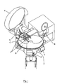
- Fig. 1 consists of a cutter bowl D, which can be driven around its (vertical) axis stored and in the to be shredded by means of a feed E Meat is eligible after processing can be removed via an ejector H.
- a cutter bowl D On one Machine stand F of the cutter is on the Cutter bowl D covering, swiveling cutter cover A, which also covers a cutter head C, for which another separate knife cover B is provided.
- the cutter head C and the knife cover B are also on the machine stand F attached like a control panel G, on which all for the Function of the cutter read the required measurement and control values can also be influenced in some cases.
- a transmitting and receiving system 1 is provided on the machine stand F and attached to this by means of a fastening I, wherein in the Fig.1 two options are indicated, such as the Knife cover B or on a holder for the knife head C.
- FIG. 2 shows the cutter head C in an exploded view, so that the knives 2 are completely visible, that is also with those used for clamping on the cutter head C.
- the recesses 4 form cavities for each a sensor chip 5 (Fig.3), which can be retracted or covered there it is appropriate that it is usually by unauthorized persons is not noticed; should it still be removed, then the shredding machine is no longer in operation settable (see below).
- the recess 4 can be relatively relatively attached to the knife 2; the arrangement shows another possibility for this 3, where they are centered in the clamping area 3 of the Knife 2 is provided.
- the sensor chip 5 which serves as a first data store, the Data can be queried and as actual values for an actual value-target value comparison serve.
- a second data store which is part of a on the Machine stand F located data processing 6 arranged is that at the same time as controlling the Kutters is networked; the data processing 6 is via a Interface 7 can be connected to a display or the like, that is formed, for example, on the control panel G. is.
- the transmitting and receiving system 1, bidirectionally with the sensor chip 5 coupled for data exchange is with the Data processing 6 via an amplifier 8 in turn bidirectionally connected; is similar to the interface 9 via an amplifier omitted in the drawing the control electronics for the cutter connected. While (Fig.1) the transmitting and receiving system 1 on the stationary Part of the cutter is provided to exchange data with the sensor chip 5 is easy to design Amplifier 8 on the machine stand F.
Landscapes
- Engineering & Computer Science (AREA)
- Food Science & Technology (AREA)
- Crushing And Pulverization Processes (AREA)
- Surgical Instruments (AREA)
- Constituent Portions Of Griding Lathes, Driving, Sensing And Control (AREA)
Description
- Fig.1
- eine Zerkleinerungs-Maschine sowie
- Fig. 2
- einen zugehörigen Messerkopf nach der Erfindung,
- Fig.3
- eine schematische Darstellung einer Einrichtung zur Datenerfassung und - verarbeitung nach der Erfindung,
- A
- Kutterdeckel
- B
- Messerdeckel
- C
- Messerkopf
- D
- Kutterschüssel
- E
- Beschickung
- F
- Maschinenständer
- G
- Bedienpult, Baueinheit
- H
- Auswerfer
- I
- Befestigung
- 1
- Sende- und Empfangsanlage
- 2
- Messer
- 3
- Spannbereich
- 4
- Ausnehmung, Hohlraum
- 5
- Sensor-Chip
- 6
- Datenverarbeitung
- 7
- Schnittstelle
- 8
- Verstärker
- 9
- Interface
Claims (10)
- Messer, insbesondere an einem Messerkopf (C) befestigbares Messer (2) für eine Zerkleinerungsmaschine zum Zerkleinern von Fleisch und/oder anderen Substanzen ähnlicher Beschaffenheit, dadurch gekennzeichnet, dass es einen Sensor-Chip (5), der in das Messer (2) eingebaut ist und der einen beschreibund abfragbaren Datenspeicher mit Daten aufweist, die zur Identifizierung des Messers geeignet sind, umfasst.
- Messer nach Anspruch 1, dadurch gekennzeichnet, dass der Sensor-Chip (5) an dem Messer (2) in einem abgeschlossenen Hohlraum (4) vorgesehen ist.
- Messer nach Anspruch 2, dadurch gekennzeichnet, dass der Sensor-Chip (5) in einem Spannbereich (3) des Messers (2) vorgesehen ist, der zum Einspannen des Messers (2) an dem Messerkopf (C) dient.
- Zerkleinerungsmaschine mit mindestens einem Messer nach einem der Ansprüche 1 bis 3, dadurch gekennzeichnet, dass der Sensor-Chip (5) mit einer an der Zerkleinerungsmaschine angeordneten oder mobilen Sende- und Empfangsanlage (1) bidirektional drahtlos gekoppelt ist.
- Zerkleinerungsmaschine nach Anspruch 4, dadurch gekennzeichnet, dass die Sende- und Empfangsanlage (1) über einen Verstärker (8) mit dem zweiten Datenspeicher und/oder einer elektronischen Maschinensteuerung verbunden ist.
- Zerkleinerungsmaschine nach Anspruch 4 oder 5, dadurch gekennzeichnet, dass die Sende- und Empfangsanlage (1) in unmittelbarer Nähe des Messerkopfes (C) vorgesehen ist.
- Zerkleinerungsmaschine nach einem der Ansprüche 4 bis 6, dadurch gekennzeichnet, dass der Verstärker (8), der zweite Datenspeicher und weitere elektronische Bau-, Anzeige- und Schaltelemente in einer gemeinsamen Baueinheit (G) an dem Maschinenständer (F) der Zerkleinerungsmaschine vorgesehen sind.
- Zerkleinerungsmaschine nach einem der Ansprüche 4 bis 7, dadurch gekennzeichnet, dass die Sende- und Empfangsanlage mit einem Verstärker und Datenspeicher versehen ist.
- Zerkleinerungsmaschine nach einem der Ansprüche 4 bis 8, dadurch gekennzeichnet, dass die Sende- und Empfangsanlage mobil zur Zerkleinerungsmaschine angeordnet ist.
- Zerkleinerungsmaschine aus einem der Ansprüche 4-9, dadurch gekennzeichnet, dass die Daten des Datenspeichers des Sensor-Chip (5) als Ist-Werte zum Abgleich mit den Daten des zweiten, der Zerkleinerungsmaschine zugeordneten Datenspeichers verwendet werden, dessen auf des Messer (2) abgestimmte Daten als Sollwert für einen Istwert-Sollwert-Vergleich dienen, wobei die Steuerung der Zerkleinerungsmaschine so ausgelegt ist, dass diese nicht in Betrieb nehmbar ist, wenn die Istwerte von den Sollwerten abweichen.
Applications Claiming Priority (3)
| Application Number | Priority Date | Filing Date | Title |
|---|---|---|---|
| DE19814012A DE19814012B4 (de) | 1998-03-28 | 1998-03-28 | Messer |
| DE19814012 | 1998-03-28 | ||
| PCT/EP1999/001260 WO1999049975A1 (de) | 1998-03-28 | 1999-02-26 | Messer |
Publications (2)
| Publication Number | Publication Date |
|---|---|
| EP1068014A1 EP1068014A1 (de) | 2001-01-17 |
| EP1068014B1 true EP1068014B1 (de) | 2004-01-14 |
Family
ID=7862850
Family Applications (1)
| Application Number | Title | Priority Date | Filing Date |
|---|---|---|---|
| EP99910293A Expired - Lifetime EP1068014B1 (de) | 1998-03-28 | 1999-02-26 | Messer |
Country Status (6)
| Country | Link |
|---|---|
| US (1) | US6382539B1 (de) |
| EP (1) | EP1068014B1 (de) |
| AT (1) | ATE257744T1 (de) |
| DE (2) | DE19814012B4 (de) |
| ES (1) | ES2158834T3 (de) |
| WO (1) | WO1999049975A1 (de) |
Cited By (1)
| Publication number | Priority date | Publication date | Assignee | Title |
|---|---|---|---|---|
| DE102005059312C5 (de) * | 2005-12-09 | 2019-11-28 | Multivac Sepp Haggenmüller Se & Co. Kg | Verpackungsmaschine |
Families Citing this family (5)
| Publication number | Priority date | Publication date | Assignee | Title |
|---|---|---|---|---|
| DE10054028A1 (de) * | 2000-10-31 | 2002-05-08 | Kraemer & Grebe Kg | Sicherheitssysteme für Zerkleinerungsmaschinen |
| DE102005052191A1 (de) * | 2005-10-28 | 2007-05-03 | Knecht Maschinenbau Gmbh | Fleischkutter |
| US8336434B2 (en) | 2007-10-22 | 2012-12-25 | Formax, Inc. | Food article end detection system for a food article slicing machine |
| DE102007050858A1 (de) * | 2007-10-24 | 2009-04-30 | Weber Maschinenbau Gmbh Breidenbach | Vorrichtung zum Aufschneiden eines Lebensmittelprodukts |
| DE102015114891A1 (de) | 2015-09-04 | 2017-03-09 | Turbocut Jopp Gmbh | Fleischwolf mit Gehäuse, mindestens einer Fördereinrichtung und mindestens einem Schneidsatzteil sowie Schneidsatzteil für einen solchen Fleischwolf |
Family Cites Families (6)
| Publication number | Priority date | Publication date | Assignee | Title |
|---|---|---|---|---|
| DE3608572A1 (de) * | 1986-03-14 | 1987-09-17 | Krupp Gmbh | Verfahren und vorrichtung zur beruehrungslosen bruch- und verschleissueberwachung von werkzeugen |
| CH675373A5 (de) * | 1988-06-10 | 1990-09-28 | Waelchli Hans | |
| US4964578A (en) * | 1988-12-01 | 1990-10-23 | Bender Martin P | Pulverizing mill control system |
| DE4022281A1 (de) * | 1990-07-12 | 1991-01-03 | Karl Prof Dr Ing Sommer | Verfahren zum ueberwachen, regeln und steuern des zerkleinerungsprozesses bei der herstellung von wurstbraet mit einem rheologischen messsensor |
| DE4317309C1 (de) * | 1993-05-25 | 1994-09-22 | Alexanderwerk Ag | Vorrichtung zur elektromagnetischen Verriegelung von einer aus einer Antriebseinheit und einer Aufsteckeinheit bestehenden Großküchenmaschine od. dgl. |
| DE19534908A1 (de) * | 1995-03-20 | 1996-09-26 | Erich Boehm | Wandung und Verfahren zur Temperaturermittlung daran befindlicher Elemente |
-
1998
- 1998-03-28 DE DE19814012A patent/DE19814012B4/de not_active Expired - Fee Related
-
1999
- 1999-02-26 WO PCT/EP1999/001260 patent/WO1999049975A1/de not_active Ceased
- 1999-02-26 EP EP99910293A patent/EP1068014B1/de not_active Expired - Lifetime
- 1999-02-26 DE DE59908308T patent/DE59908308D1/de not_active Expired - Fee Related
- 1999-02-26 AT AT99910293T patent/ATE257744T1/de not_active IP Right Cessation
- 1999-02-26 ES ES99910293T patent/ES2158834T3/es not_active Expired - Lifetime
-
2000
- 2000-09-21 US US09/666,031 patent/US6382539B1/en not_active Expired - Fee Related
Cited By (1)
| Publication number | Priority date | Publication date | Assignee | Title |
|---|---|---|---|---|
| DE102005059312C5 (de) * | 2005-12-09 | 2019-11-28 | Multivac Sepp Haggenmüller Se & Co. Kg | Verpackungsmaschine |
Also Published As
| Publication number | Publication date |
|---|---|
| EP1068014A1 (de) | 2001-01-17 |
| DE59908308D1 (de) | 2004-02-19 |
| ATE257744T1 (de) | 2004-01-15 |
| ES2158834T1 (es) | 2001-09-16 |
| WO1999049975A1 (de) | 1999-10-07 |
| ES2158834T3 (es) | 2004-11-01 |
| US6382539B1 (en) | 2002-05-07 |
| DE19814012A1 (de) | 1999-10-07 |
| DE19814012B4 (de) | 2004-07-15 |
Similar Documents
| Publication | Publication Date | Title |
|---|---|---|
| EP1201312B1 (de) | Sicherheitssysteme für Zerkleinerungsmaschinen | |
| EP2332404B1 (de) | Häckseltrommel für einen Feldhäcksler | |
| WO2006000270A1 (de) | Werkzeug-haltevorrichtung | |
| EP3501744B1 (de) | Werkzeug für die montage eines meissels an und/oder die demontage eines meissels von einem meisselhaltersystem einer fräsmaschine | |
| EP2796251A2 (de) | Lebensmittelaufschneidemesser mit einem Funktransponder | |
| EP2386200A1 (de) | Selbstfahrender Feldhäcksler | |
| EP3738428A1 (de) | Fahrerassistenzsystem eines feldhäckslers | |
| DE202020106963U1 (de) | Elektrowerkzeug mit einem intelligent-erkennungsfähigen, trennbaren Arbeitskopf | |
| EP3344395B1 (de) | Fleischwolf mit gehäuse, mindestens einer fördereinrichtung und mindestens einem schneidsatzteil | |
| WO1999049975A1 (de) | Messer | |
| EP0249840B1 (de) | Vorrichtung zum automatischen Verstellen des Schneidsatzes einer Fleischzerkleinerungsmaschine | |
| EP1935595B1 (de) | Vorrichtung und Verfahren zur Zerkleinerung von Holzstämmen | |
| EP2255882A1 (de) | Zerkleinerungsmaschine und Werkzeug zum Einsatz in einer Zerkleinerungsmaschine | |
| EP1371420B1 (de) | Zerkleinerungsmaschine zum Verkleinern von Material | |
| EP1196244B1 (de) | Maschine zum zerkleinern von organischem schnittgut | |
| EP4122313A1 (de) | Verfahren zur bestimmung des verschleisszustandes einer an einem gegenschneideträger angeordneten gegenschneide sowie selbstfahrender feldhäcksler | |
| DE10022849A1 (de) | Zerkleinerungsmühle | |
| EP2014371B1 (de) | Häcksler | |
| DE1193721B (de) | Haeckselmaschine fuer landwirtschaftliche Produkte, insbesondere Scheibenradhaecksler | |
| DE20216056U1 (de) | Vorrichtung zum Zerkleinern von Aufgabegut | |
| DE102010054994B4 (de) | Hackmesserwalze für eine Holzhackmaschine | |
| EP2394742A1 (de) | Zerkleinerungsmaschine | |
| DE202025100406U1 (de) | Vorrichtung zur Zerkleinerung von Fleisch und anderen organischen Materialien sowie Lese- und/oder Schreib-Leseeinrichtung hierfür | |
| DE102010014799A1 (de) | Schneidplatte für eine Vorrichtung zum Zerkleinern von kompostierbarem Material | |
| DE19537581C2 (de) | Messeranordnung für eine Zerkleinerungsvorrichtung, zugehöriges Messer und Verfahren zu dessen Herstellung |
Legal Events
| Date | Code | Title | Description |
|---|---|---|---|
| PUAI | Public reference made under article 153(3) epc to a published international application that has entered the european phase |
Free format text: ORIGINAL CODE: 0009012 |
|
| 17P | Request for examination filed |
Effective date: 20001030 |
|
| AK | Designated contracting states |
Kind code of ref document: A1 Designated state(s): AT BE CH CY DE DK ES FI FR GB GR IE IT LI LU MC NL PT SE |
|
| EL | Fr: translation of claims filed | ||
| RAP1 | Party data changed (applicant data changed or rights of an application transferred) |
Owner name: CONVENIENCE FOOD SYSTEMS WALLAU GMBH & CO. KG |
|
| REG | Reference to a national code |
Ref country code: ES Ref legal event code: BA2A Ref document number: 2158834 Country of ref document: ES Kind code of ref document: T1 |
|
| 17Q | First examination report despatched |
Effective date: 20021216 |
|
| GRAP | Despatch of communication of intention to grant a patent |
Free format text: ORIGINAL CODE: EPIDOSNIGR1 |
|
| GRAS | Grant fee paid |
Free format text: ORIGINAL CODE: EPIDOSNIGR3 |
|
| GRAA | (expected) grant |
Free format text: ORIGINAL CODE: 0009210 |
|
| AK | Designated contracting states |
Kind code of ref document: B1 Designated state(s): AT BE CH CY DE DK ES FI FR GB GR IE IT LI LU MC NL PT SE |
|
| PG25 | Lapsed in a contracting state [announced via postgrant information from national office to epo] |
Ref country code: NL Free format text: LAPSE BECAUSE OF FAILURE TO SUBMIT A TRANSLATION OF THE DESCRIPTION OR TO PAY THE FEE WITHIN THE PRESCRIBED TIME-LIMIT Effective date: 20040114 Ref country code: IT Free format text: LAPSE BECAUSE OF FAILURE TO SUBMIT A TRANSLATION OF THE DESCRIPTION OR TO PAY THE FEE WITHIN THE PRE;WARNING: LAPSES OF ITALIAN PATENTS WITH EFFECTIVE DATE BEFORE 2007 MAY HAVE OCCURRED AT ANY TIME BEFORE 2007. THE CORRECT EFFECTIVE DATE MAY BE DIFFERENT FROM THE ONE RECORDED.SCRIBED TIME-LIMIT Effective date: 20040114 Ref country code: IE Free format text: LAPSE BECAUSE OF FAILURE TO SUBMIT A TRANSLATION OF THE DESCRIPTION OR TO PAY THE FEE WITHIN THE PRESCRIBED TIME-LIMIT Effective date: 20040114 Ref country code: GB Free format text: LAPSE BECAUSE OF FAILURE TO SUBMIT A TRANSLATION OF THE DESCRIPTION OR TO PAY THE FEE WITHIN THE PRESCRIBED TIME-LIMIT Effective date: 20040114 Ref country code: FI Free format text: LAPSE BECAUSE OF FAILURE TO SUBMIT A TRANSLATION OF THE DESCRIPTION OR TO PAY THE FEE WITHIN THE PRESCRIBED TIME-LIMIT Effective date: 20040114 Ref country code: CY Free format text: LAPSE BECAUSE OF FAILURE TO SUBMIT A TRANSLATION OF THE DESCRIPTION OR TO PAY THE FEE WITHIN THE PRESCRIBED TIME-LIMIT Effective date: 20040114 |
|
| REG | Reference to a national code |
Ref country code: GB Ref legal event code: FG4D Free format text: NOT ENGLISH |
|
| REG | Reference to a national code |
Ref country code: CH Ref legal event code: EP |
|
| REG | Reference to a national code |
Ref country code: IE Ref legal event code: FG4D Free format text: GERMAN |
|
| REF | Corresponds to: |
Ref document number: 59908308 Country of ref document: DE Date of ref document: 20040219 Kind code of ref document: P |
|
| PG25 | Lapsed in a contracting state [announced via postgrant information from national office to epo] |
Ref country code: LU Free format text: LAPSE BECAUSE OF NON-PAYMENT OF DUE FEES Effective date: 20040226 |
|
| PG25 | Lapsed in a contracting state [announced via postgrant information from national office to epo] |
Ref country code: MC Free format text: LAPSE BECAUSE OF NON-PAYMENT OF DUE FEES Effective date: 20040228 Ref country code: BE Free format text: LAPSE BECAUSE OF NON-PAYMENT OF DUE FEES Effective date: 20040228 |
|
| PG25 | Lapsed in a contracting state [announced via postgrant information from national office to epo] |
Ref country code: SE Free format text: LAPSE BECAUSE OF FAILURE TO SUBMIT A TRANSLATION OF THE DESCRIPTION OR TO PAY THE FEE WITHIN THE PRESCRIBED TIME-LIMIT Effective date: 20040414 Ref country code: GR Free format text: LAPSE BECAUSE OF FAILURE TO SUBMIT A TRANSLATION OF THE DESCRIPTION OR TO PAY THE FEE WITHIN THE PRESCRIBED TIME-LIMIT Effective date: 20040414 Ref country code: DK Free format text: LAPSE BECAUSE OF FAILURE TO SUBMIT A TRANSLATION OF THE DESCRIPTION OR TO PAY THE FEE WITHIN THE PRESCRIBED TIME-LIMIT Effective date: 20040414 |
|
| NLV1 | Nl: lapsed or annulled due to failure to fulfill the requirements of art. 29p and 29m of the patents act | ||
| GBV | Gb: ep patent (uk) treated as always having been void in accordance with gb section 77(7)/1977 [no translation filed] |
Effective date: 20040114 |
|
| REG | Reference to a national code |
Ref country code: IE Ref legal event code: FD4D |
|
| BERE | Be: lapsed |
Owner name: CONVENIENCE FOOD SYSTEMS WALLAU G.M.B.H. & CO. KG Effective date: 20040228 |
|
| REG | Reference to a national code |
Ref country code: ES Ref legal event code: FG2A Ref document number: 2158834 Country of ref document: ES Kind code of ref document: T3 |
|
| ET | Fr: translation filed | ||
| PLBE | No opposition filed within time limit |
Free format text: ORIGINAL CODE: 0009261 |
|
| STAA | Information on the status of an ep patent application or granted ep patent |
Free format text: STATUS: NO OPPOSITION FILED WITHIN TIME LIMIT |
|
| 26N | No opposition filed |
Effective date: 20041015 |
|
| PGFP | Annual fee paid to national office [announced via postgrant information from national office to epo] |
Ref country code: ES Payment date: 20070425 Year of fee payment: 9 |
|
| PG25 | Lapsed in a contracting state [announced via postgrant information from national office to epo] |
Ref country code: PT Free format text: LAPSE BECAUSE OF NON-PAYMENT OF DUE FEES Effective date: 20040614 |
|
| PGFP | Annual fee paid to national office [announced via postgrant information from national office to epo] |
Ref country code: FR Payment date: 20070418 Year of fee payment: 9 Ref country code: CH Payment date: 20080225 Year of fee payment: 10 |
|
| PGFP | Annual fee paid to national office [announced via postgrant information from national office to epo] |
Ref country code: AT Payment date: 20080222 Year of fee payment: 10 |
|
| PGFP | Annual fee paid to national office [announced via postgrant information from national office to epo] |
Ref country code: DE Payment date: 20080423 Year of fee payment: 10 |
|
| REG | Reference to a national code |
Ref country code: FR Ref legal event code: ST Effective date: 20081031 |
|
| PG25 | Lapsed in a contracting state [announced via postgrant information from national office to epo] |
Ref country code: FR Free format text: LAPSE BECAUSE OF NON-PAYMENT OF DUE FEES Effective date: 20080229 |
|
| REG | Reference to a national code |
Ref country code: ES Ref legal event code: FD2A Effective date: 20080227 |
|
| PG25 | Lapsed in a contracting state [announced via postgrant information from national office to epo] |
Ref country code: ES Free format text: LAPSE BECAUSE OF NON-PAYMENT OF DUE FEES Effective date: 20080227 |
|
| REG | Reference to a national code |
Ref country code: CH Ref legal event code: PL |
|
| PG25 | Lapsed in a contracting state [announced via postgrant information from national office to epo] |
Ref country code: LI Free format text: LAPSE BECAUSE OF NON-PAYMENT OF DUE FEES Effective date: 20090228 Ref country code: CH Free format text: LAPSE BECAUSE OF NON-PAYMENT OF DUE FEES Effective date: 20090228 Ref country code: AT Free format text: LAPSE BECAUSE OF NON-PAYMENT OF DUE FEES Effective date: 20090226 |
|
| PG25 | Lapsed in a contracting state [announced via postgrant information from national office to epo] |
Ref country code: DE Free format text: LAPSE BECAUSE OF NON-PAYMENT OF DUE FEES Effective date: 20090901 |