EP1067684A2 - Trägerstruktur für einen piezoelektrischen Resonator, elektronische Anordnung , Abzweigfilter und Kommunikationsgerät - Google Patents
Trägerstruktur für einen piezoelektrischen Resonator, elektronische Anordnung , Abzweigfilter und Kommunikationsgerät Download PDFInfo
- Publication number
- EP1067684A2 EP1067684A2 EP00114233A EP00114233A EP1067684A2 EP 1067684 A2 EP1067684 A2 EP 1067684A2 EP 00114233 A EP00114233 A EP 00114233A EP 00114233 A EP00114233 A EP 00114233A EP 1067684 A2 EP1067684 A2 EP 1067684A2
- Authority
- EP
- European Patent Office
- Prior art keywords
- piezoelectric resonator
- major surface
- electrodes
- resiliency
- rupture strength
- Prior art date
- Legal status (The legal status is an assumption and is not a legal conclusion. Google has not performed a legal analysis and makes no representation as to the accuracy of the status listed.)
- Withdrawn
Links
Images


Classifications
-
- H—ELECTRICITY
- H10—SEMICONDUCTOR DEVICES; ELECTRIC SOLID-STATE DEVICES NOT OTHERWISE PROVIDED FOR
- H10N—ELECTRIC SOLID-STATE DEVICES NOT OTHERWISE PROVIDED FOR
- H10N30/00—Piezoelectric or electrostrictive devices
- H10N30/80—Constructional details
- H10N30/88—Mounts; Supports; Enclosures; Casings
-
- H—ELECTRICITY
- H03—ELECTRONIC CIRCUITRY
- H03H—IMPEDANCE NETWORKS, e.g. RESONANT CIRCUITS; RESONATORS
- H03H9/00—Networks comprising electromechanical or electro-acoustic elements; Electromechanical resonators
- H03H9/15—Constructional features of resonators consisting of piezoelectric or electrostrictive material
- H03H9/17—Constructional features of resonators consisting of piezoelectric or electrostrictive material having a single resonator
- H03H9/178—Constructional features of resonators consisting of piezoelectric or electrostrictive material having a single resonator of a laminated structure of multiple piezoelectric layers with inner electrodes
-
- H—ELECTRICITY
- H03—ELECTRONIC CIRCUITRY
- H03H—IMPEDANCE NETWORKS, e.g. RESONANT CIRCUITS; RESONATORS
- H03H9/00—Networks comprising electromechanical or electro-acoustic elements; Electromechanical resonators
- H03H9/02—Details
- H03H9/05—Holders or supports
- H03H9/0504—Holders or supports for bulk acoustic wave devices
- H03H9/0514—Holders or supports for bulk acoustic wave devices consisting of mounting pads or bumps
-
- H—ELECTRICITY
- H03—ELECTRONIC CIRCUITRY
- H03H—IMPEDANCE NETWORKS, e.g. RESONANT CIRCUITS; RESONATORS
- H03H9/00—Networks comprising electromechanical or electro-acoustic elements; Electromechanical resonators
- H03H9/46—Filters
- H03H9/54—Filters comprising resonators of piezoelectric or electrostrictive material
- H03H9/58—Multiple crystal filters
- H03H9/60—Electric coupling means therefor
- H03H9/605—Electric coupling means therefor consisting of a ladder configuration
Definitions
- the present invention relates to supporting structures for piezoelectric resonators, and relates to electronic devices, ladder filters, and communication apparatuses.
- the present invention relates to a supporting structure for a piezoelectric resonator in which the piezoelectric resonator using, for example, length vibration or spread vibration, is supported by a supporting member on a substrate at an approximate center of the piezoelectric resonator.
- the present invention also relates to an electronic device, such as a ceramic filter, discriminator, or a ceramic oscillator, to a ladder filter, and to a communication apparatus which include the supporting structures.
- the inventors of the present invention proposed a structure in which a piezoelectric resonator having a layered structure and using length vibration was provided with a supporting member made of a conductive resin at an intermediate portion in the longitudinal direction of the piezoelectric resonator, and was supported by and electrically connected to a substrate through the supporting member.
- the inventors also proposed another structure in which a piezoelectric resonator having a layered structure was provided with a supporting member made of an insulative resin at an intermediate portion in the longitudinal direction of the piezoelectric resonator, supported by the supporting member on a substrate, and electrically connected to the substrate through wires or other suitable connectors.
- a flexible supporting member having low resiliency is used, thereby minimizing the effect on the deflection by the vibration of the piezoelectric resonator.
- a material having a high rupture strength is required to be used for the supporting member because it must have a strength that is sufficiently high so as to be durable against impacts caused by falling or other environmental conditions.
- preferred embodiments of the present invention provide a supporting structure for a piezoelectric resonator having high strength against impacts, in which superior resonance characteristics are obtained.
- preferred embodiments of the present invention provide an electronic device, a ladder filter, and a communication apparatus, each using the supporting structure for a piezoelectric resonator having high strength against impacts, in which superior resonance characteristics are obtained.
- a supporting structure for a piezoelectric resonator preferably includes a piezoelectric resonator, a substrate, and a supporting member for supporting the piezoelectric resonator on the substrate at an approximate center of a major surface of the piezoelectric resonator.
- the piezoelectric resonator vibrates in a direction that is substantially parallel to the major surface.
- the supporting member is made of a first material having relatively high rupture strength and high resiliency and a second material having relatively low rupture strength and low resiliency. The interface between the first and second materials is arranged substantially perpendicular to the major surface of the piezoelectric resonator.
- the piezoelectric resonator may use length vibration, and the interface between the materials may be arranged substantially perpendicular to a surface of the substrate.
- the supporting member may include at least one substantially cylindrical unit extending substantially perpendicular to the major surface of the piezoelectric resonator and a filler arranged around the substantially cylindrical unit.
- the substantially cylindrical unit has a rupture strength higher than the rupture strength of the filler, and the filler has a resiliency lower than the resiliency of the substantially cylindrical unit.
- the piezoelectric resonator may have a layered structure including a piezoelectric layer and electrodes laminated in the longitudinal direction of the major surface of the piezoelectric resonator, and may use length vibration in the longitudinal direction of the major surface of the piezoelectric resonator.
- an insulating film may be arranged on a part of one of the major surface and side surfaces of the piezoelectric resonator at which the electrodes are exposed, and two external electrodes may be located on one of the major surface and the side surfaces of the piezoelectric resonator, which include a surface of the insulating film, whereby the electrodes are connected to one of the two external electrodes.
- the material of the substantially cylindrical unit having relatively high rupture strength and high resiliency may be made of a material selected from the group consisting of a resin, a metal, and a resin coated with a metal, and the other material for the filler having relatively low rupture strength and low resiliency may be made of an insulative resin.
- land electrodes may be arranged to project from the surface of the substrate, and the piezoelectric resonator may be supported by the supporting member on the land electrodes.
- two external electrodes may be located on one of the side surfaces of the piezoelectric resonator, and each of the two external electrodes may be electrically connected to one of the land electrodes through the supporting member.
- an electronic device preferably includes a supporting structure for a piezoelectric resonator according to preferred embodiments of the support structure described above.
- a ladder filter in which a plurality of piezoelectric resonators are disposed on a substrate by using a supporting structure for a piezoelectric resonator according to preferred embodiments of the support structure described above.
- a communication apparatus preferably includes one of a supporting structure for a piezoelectric resonator and a ladder filter according to preferred embodiments described above.
- a problem to be solved in known technologies is the compatibility of the rupture strength of the supporting member with the resiliency thereof.
- the piezoelectric resonator using length vibration or spread vibration, rupture strength is required to be active in a direction in which the piezoelectric resonator peels off of the substrate, that is, in a direction that is perpendicular to the surface of the substrate (Z-direction).
- the rupture strength is not required in a direction that is parallel to the surface of the substrate (X-Y directions). Since the piezoelectric resonator vibrates in the X-Y directions, resiliency of the supporting member is required to be low in those directions, and the resiliency in the Z-direction is not important.
- the supporting member according to preferred embodiments of the present invention is provided with resiliency and rupture strength which are made different according to the orientation and arrangement thereof.
- the supporting member includes an element such as a substantially cylindrical unit having relatively high rupture strength and resiliency, and another element such as a filler having relatively low rupture strength and resiliency.
- the element such as the substantially cylindrical unit is disposed substantially perpendicular to the substrate, whereby the supporting member has a high rupture strength in the Z-direction and a low resiliency in the X-Y directions.
- the piezoelectric resonator vibrates in the X-Y directions, while tensile force to break the junction between the substrate and the piezoelectric resonator is applied in the Z-direction.
- the supporting member of a piezoelectric resonator by virtue of a low resiliency in the X-Y directions of the supporting member, superior resonance characteristics are ensured, and by virtue of a high rupture strength in the Z-direction, a very high strength against impacts due to falls and other conditions is achieved.
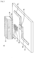
- Fig. 1 is a perspective view of a piezoelectric device according to a first preferred embodiment of the present invention.
- Fig. 2 is an exploded perspective view of the same.
- Fig. 3 is a perspective view of a piezoelectric resonator included in the piezoelectric device shown in Figs. 1 and 2.
- a piezoelectric device 10 shown in Fig. 1 preferably includes a substrate 12 made of, for example, a glass epoxy resin.
- the substrate 12 is provided preferably with two pattern-electrodes 14a and 14b located on one of the major surfaces of the substrate 12 across a gap therebetween.
- the pattern electrode 14a has a substantially L-shaped configuration and an end that extends toward the center of the substrate 12.
- the pattern electrode 14b also has a substantially L-shaped configuration and an end that extends toward the center of the substrate 12.
- the ends of the pattern electrodes 14a and 14b define land electrodes 16a and 16b which project by, for example, about 0.1 mm from the surface of the substrate 12.
- the land electrodes 16a and 16b of the pattern electrodes 14a and 14b support a multilayer piezoelectric resonator 20 through a supporting member 40 at an intermediate portion in the longitudinal direction of the piezoelectric resonator 20.
- the piezoelectric resonator 20 preferably includes a substantially rectangular base member 22 having, for example, a length of about 4 mm, a width of about 0.5 mm, and a thickness of about 0.4 mm.
- the base member 22 made of, for example, a piezoelectric ceramic includes twenty piezoelectric layers 24 arranged in a laminated construction.
- the piezoelectric layers 24 preferably have a uniform size.
- Each of the piezoelectric layers 24 is polarized in a direction opposite to the direction of polarization of the piezoelectric layers 24 adjacent thereto in the longitudinal direction of the base member 22.
- the piezoelectric layer 24 disposed at each longitudinal end of the base member 22 is not polarized.
- the base member 22 is provided with internal electrodes 26 disposed between each of the twenty piezoelectric layers 24.
- the internal electrodes 26 extend substantially perpendicular to the longitudinal direction of the base member 22 and are separated from each other in the longitudinal direction of the base member 22.
- the internal electrodes 26 are arranged to cover the entire major surface of each piezoelectric layer 24.
- the internal electrodes 26 are exposed at the major surfaces and the side surfaces of the base member 22.
- first alternate internal electrodes 26 are covered by insulating films 28 at one widthwise side of one of the major surfaces of the base member 22.
- Ends of the other alternate internal electrodes (second alternate internal electrodes) 26 are covered by insulating films 30 at the other widthwise side of the major surface of the base member 22.
- An external electrode 32 is provided on the major surface of the base member 22 across the insulating films 28 provided on the first alternate internal electrodes 26, and is connected to the second alternate internal electrodes 26.
- An external electrode 34 is disposed on the major surface of the base member 22 across the insulating films 30 provided on the second alternate internal electrodes 26, and is connected to the first alternate internal electrodes 26.
- the external electrodes 32 and 34 function as input/output electrodes.
- electrical fields are applied between the internal electrodes 26 of the adjacent layers, thereby piezoelectrically activating each of the piezoelectric layers 24 except the piezoelectric layers 24 at the longitudinal ends of the base member 22.
- each electrical field opposite to the adjacent electrical fields is applied to each piezoelectric layer 24 of the base member 22 polarized in a direction opposite to the adjacent piezoelectric layers 24, whereby the piezoelectric layers 24, as a unit, expand or contract in the same direction.
- an alternating electrical field in the longitudinal direction of the base member 22 is applied to each of the piezoelectric layers 24 through the internal electrodes 26 connected to the external electrodes 32 and 34, thereby driving each piezoelectric layer 24 to expand or contract, whereby a basic length vibration is generated in the piezoelectric resonator 20 with a node at a longitudinal intermediate portion of the base member 22.
- the supporting member 40 preferably includes a plurality of substantially cylindrical units 42 made of, for example, nickel in a substantially cylindrical shape having a diameter of about 0.005 mm.
- a filler 44 is disposed around the substantially cylindrical units 42.
- the filler 44 is preferably made of, for example, an epoxy resin and has a length of about 1 mm, a width of about 0.5 mm, and a thickness of about 0.05 mm.
- the plurality of substantially cylindrical units 42 are disposed across a gap of, for example, approximately 0.025 mm between each other, passing through the filler 44 in the thickness direction.
- the piezoelectric resonator 20 is supported by the supporting member 40 on the land electrodes 16a and 16b of the pattern electrodes 14a and 14b at longitudinal intermediate portions of the external electrodes 32 and 34 provided on the piezoelectric resonator 20.
- the external electrodes 32 and 34 of the piezoelectric resonator 20 are electrically connected to the land electrodes 16a and 16b of the pattern electrodes 14a and 14b, respectively, through the substantially cylindrical units 42 of the supporting member 40.
- Table 1 shows the resiliency and the rupture strength required of components included in the piezoelectric device 10 shown in Figs. 1 and 2.
- the resiliency of the supporting member 40 in the X-Y directions is preferably not more than about 49 ⁇ 10 9 N/m 2 and the rupture strength of the same in the Z-direction is preferably not less than about 0.069 ⁇ 10 9 N/m 2 , which is found, in Table 1, to be possible in various preferred embodiments of the present invention.
- the piezoelectric resonator 20 is supported on the substrate 12 by the supporting member 40 having a relatively low resiliency in the vibration direction of the piezoelectric resonator 20 using length vibration and having a relatively high rupture strength in a direction in which the piezoelectric resonator 20 peels away, whereby superior resonance characteristics are achieved and the strength against impacts due to falls and other conditions is greatly increased.
- the piezoelectric device 10 shown in Figs. 1 and 2 includes the supporting member 40 having the substantially cylindrical units 42 made of conductive nickel and the filler 44 of an insulative epoxy resin.
- the supporting member 40 also functions to electrically connect the external electrodes 32 and 34 of the piezoelectric resonator 20 to the land electrodes 16a and 16b of the pattern electrodes 14a and 14b, respectively, provided on the substrate 12.
- the supporting member 40 which has the substantially cylindrical units 42 disposed across a gap between each other, is conductive in the Z-direction and is insulative in the X-Y directions.
- the land electrodes 16a and 16b of the pattern electrodes 14a and l4b are arranged to project from the surface of the substrate 10. Due to this configuration, a sufficient gap is ensured between an end of the piezoelectric resonator 20 and the surface of the substrate 12 so as not to suppress or hinder the vibration of the piezoelectric resonator 20, even when the piezoelectric resonator 20 is mounted slightly inclined, thereby yielding superior resonance characteristics.
- Fig. 4 is a perspective view of a piezoelectric device 10 according to a second preferred embodiment of the present invention
- Fig. 5 is an exploded perspective view of the same.
- pattern electrodes 14a and 14b are disposed across a larger gap therebetween than that provided between the pattern electrodes 14a and 14b of the piezoelectric device 10 shown in Figs. 1 and 2, according to the first preferred embodiment.
- a piezoelectric resonator 20 preferably includes first alternate internal electrodes 26 having ends covered by insulating films 28 at one side of a base member 22, and the other alternate internal electrodes (second alternate internal electrodes) 26 having ends being covered by insulating films 30 at the other side of the base member 22.
- An external electrode 32 is formed on the insulating films 28 provided on the first alternate internal electrodes 26 at the side of the base member 22.
- An external electrode 34 is formed on the insulating films 30 provided on the second alternate internal electrodes 26 at the other side of the base member 22.
- a supporting member 40 includes a plurality of substantially cylindrical units 42 preferably made of an epoxy resin and a filler 44 preferably made of a urethane resin.
- the piezoelectric resonator 20 is supported on a surface of a substrate 12 by the supporting member 40 at a longitudinal intermediate portion of the major surface of the piezoelectric resonator 20 which is not provided with the external electrodes 32 and 34.
- the external electrodes 32 and 34 of the piezoelectric resonator 20 are electrically connected to the pattern electrodes 14a and 14b through wires 36 and 38, respectively. However, other suitable connections can also be used.
- the piezoelectric device 10 according to the second preferred embodiment shown in Figs. 4 and 5 includes, in the same way as in the piezoelectric device 10 according to the first preferred embodiment shown in Figs. 1 and 2, the supporting member having low resiliency in the X-Y directions and high rupture strength in the Z-direction, whereby the vibration of the piezoelectric resonator 20 is not suppressed or hindered, thereby yielding superior resonance characteristics and ensuring strength sufficient against impacts due to falls or other conditions.
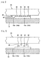
- Fig. 6 is a side view of a piezoelectric device according to a third preferred embodiment of the present invention.
- Fig. 7 is an exploded perspective view of the piezoelectric device.
- a piezoelectric device 10 shown in Figs. 6 and 7 is different from the piezoelectric device 10 according to the first preferred embodiment shown in Figs. 1 and 2, in that the piezoelectric device 10 shown in Figs. 6 and 7 includes a piezoelectric resonator 20 that is constructed to vibrate in the spread vibration mode.
- the piezoelectric resonator 20 includes a substantially square plate-shaped piezoelectric layer 24.
- Two external electrodes 32 and 34 are located on a major surface of the piezoelectric layer 24 by dividing one electrode provided on the major surface into two electrodes at an intermediate portion thereof. Another external electrode 35 is located on the other major surface of the piezoelectric layer 24.
- the piezoelectric layer 24 is polarized in the thickness direction. As shown by arrows in Fig. 6, the piezoelectric layer 24 is polarized in the thickness directions opposite to each other: in one direction in a portion provided with the external electrode 32 and in the other direction in a portion provided with the external electrode 34.
- the piezoelectric resonator 20 is supported by a supporting member 40 on land electrodes 16a and 16b of pattern electrodes 14a and 14b at the approximate center of the piezoelectric layer 24 of the piezoelectric resonator 20.
- the external electrodes 32 and 34 of the piezoelectric resonator 20 are electrically connected to the land electrodes 16a and 16b of the pattern electrodes 14a and 14b, respectively, through substantially cylindrical units 42 of the supporting member 40.
- the direction of vibration of the piezoelectric resonator 22 using spread vibration is substantially parallel to the surface of the substrate 12, thereby yielding superior resonance characteristics and sufficient supporting strength, in the same way as in the operation of the piezoelectric resonator using length vibration according to preferred embodiments described above.
- Fig. 8 is an illustration of a piezoelectric device according to a fourth preferred embodiment of the present invention.
- the piezoelectric device shown in Fig. 8 is different from the piezoelectric device 10 according to the first preferred embodiment shown in Figs. 1 and 2, in that the piezoelectric device according to the fourth preferred embodiment shown in Fig. 8 includes a supporting member 40 in which substantially cylindrical units 42 are constructed in a shape of balls that are vertically compressed.
- a supporting member 40 can be formed using the following method. That is, an appropriate quantity of round resin grains to serve as the substantially cylindrical units 42 are mixed and dispersed in a resin to form a filler 44. As shown in Fig.
- the mixed resin is disposed on a land electrode 16a (16b) of a pattern electrode 14a (14b) provided on a substrate 12, the piezoelectric resonator 20 is disposed on the mixed resin layer, and the thus-assembled components are compressed, heated, and cured, thereby forming the supporting member 40 shown in Fig. 8.
- the rupture strength in the direction of compression is greatly increased and the resiliency in a direction that is substantially perpendicular to the direction of compression is greatly decreased.
- the supporting member 40 has a low resiliency in the X-Y directions and a high rupture strength in the Z-direction, whereby the vibration of the piezoelectric resonator 20 is not suppressed, thereby yielding superior resonance characteristics and sufficient strength against impacts due to falls or other conditions.
- the substantially cylindrical units 42 made of a resin, as described above, can be used in the piezoelectric device 10 according to the second preferred embodiment shown in Fig. 4, in which the substantially cylindrical units 42 are not required to be electrically conductive.
- the substantially cylindrical units 42 may be electrically conductive by using a material of a metal or a resin coated with a metal, whereby it can be used in the piezoelectric device 10 according to the first and third preferred embodiments shown in Figs. 1 and 6.
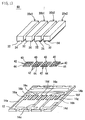
- Fig. 10 is an exploded perspective view of a piezoelectric device 10 according to a fifth preferred embodiment of the present invention.
- the piezoelectric device 10 shown in Fig. 10 is different from the piezoelectric device 10, according to the first preferred embodiment, shown in Figs. 1 and 2, in that the piezoelectric device 10 shown in Fig. 10 includes a supporting member 40 having a plurality of plate-shaped units 42 extending in a direction that is substantially perpendicular to the longitudinal direction of a piezoelectric resonator 20, and the supporting member 40 is divided into two portions corresponding to lands 16a and 16b and external electrodes 32 and 34, respectively.
- the piezoelectric resonator 20 vibrates in the X-direction, such as in the case of the piezoelectric device 10, according to the fifth preferred embodiment, of which the supporting member 40 has a shape shown in Fig. 10.
- the piezoelectric resonator 20 is supported on a substrate 12 by the supporting member 40 having a relatively low resiliency in the vibration direction of the piezoelectric resonator 20 using length vibration and a relatively high rupture strength in a direction in which the piezoelectric resonator 20 peels away, thereby yielding superior resonance characteristics and a high strength against impacts due to falls or other conditions.
- Fig. 11 is a plan view of a ladder filter 50 according to another preferred embodiment of the present invention
- Fig. 12 is an exploded perspective view of the same.
- the ladder filter 50 shown in Figs. 11 and 12 preferably has four pattern electrodes 14a, 14b, 14c, and 14d arranged across a gap therebetween on a major surface of a substrate 12.
- the pattern electrodes 14a to 14d are provided with eight land electrodes 16a to 16h disposed substantially parallel to each other across a gap therebetween.
- the land electrode 16a is located at an end of the pattern electrode 14a.
- the land electrodes 16b and 16c are located at an end of the pattern electrode 14b.
- the land electrodes 16d and 16e are located at an end of the pattern electrode 14c.
- the land electrode 16f and 16g are located at an end of the pattern electrode 14d.
- the land electrode 16h is located at the other end of the pattern electrode 14b.
- the eight land electrodes 16a to 16h on the substrate 12 support four piezoelectric resonators 20a1, 20b1, 20b2, and 20a2 at intermediate portions of each piezoelectric resonator through four supporting members 40.
- External electrodes of each piezoelectric resonator are electrically connected to the land electrodes through substantially cylindrical units 42 of the supporting members 40 in such a manner: external electrodes 32 and 34 of the piezoelectric resonator 20a1 to the land electrodes 16a and 16b, respectively, external electrodes 32 and 34 of the piezoelectric resonator 20b1 to the land electrodes 16c and 16d, respectively, external electrodes 32 and 34 of the piezoelectric resonator 20b2 to the land electrodes 16e and 16f, respectively, and external electrodes 32 and 34 of the piezoelectric resonator 20a2 to the land electrodes 16g and 16h, respectively.
- Fig. 13 is a schematic diagram of a circuit of the ladder filter 50 thus arranged.
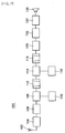
- FIG. 14 is a block diagram of a double superheterodyne receiver according to an additional preferred embodiment of the present invention.
- a double superheterodyne receiver 100 shown in Fig. 14 includes an antenna 102.
- the antenna 102 is connected to an input terminal of an input circuit 104.
- the input circuit 104 performs impedance matching between the antenna 102 and a high-frequency amplifier 106 described below.
- the input circuit 104 includes a tuning circuit or a band-pass filter for selecting a given wave.
- An output terminal of the input circuit 104 is connected to an input terminal of the high-frequency amplifier 106.
- the high-frequency amplifier 106 low-noise-amplifies an extremely-low-power electric wave and improves the sensitivity, and it improves selectivity of image frequency.
- An output terminal of the high-frequency amplifier 106 is connected to an input terminal of a first frequency mixer 108.
- the first frequency mixer 108 mixes the given wave and a local oscillator wave, and produces a first intermediate frequency wave with the sum or the difference thereof.
- the other input terminal of the first frequency mixer 108 is connected to an output terminal of a first local oscillator 110.
- the first local oscillator 110 outputs the first local oscillator wave for producing the first intermediate frequency wave.
- An output terminal of the first frequency mixer 108 is connected to an input terminal of a first band-pass filter 112.
- the first band-pass filter 112 transmits the first intermediate frequency wave.
- An output terminal of the first band-pass filter 112 is connected to an input terminal of a second frequency mixer 114.
- the second frequency mixer 114 mixes the first intermediate frequency wave and a second local oscillator wave, and produces a second intermediate frequency wave with the sum or the difference thereof.
- the other input terminal of the second frequency mixer 114 is connected to an output terminal of a second local oscillator 116.
- the second local oscillator 116 outputs the second local oscillator wave for producing the second intermediate frequency wave.
- An output terminal of the second frequency mixer 114 is connected to an input terminal of a second band-pass filter 118.
- the second band-pass filter 118 transmits the second intermediate frequency wave.
- An output terminal of the second band-pass filter 118 is connected to an input terminal of an intermediate frequency amplifier 120.
- the intermediate frequency amplifier 120 amplifies the second intermediate frequency wave.
- An output terminal of the intermediate frequency amplifier 120 is connected to an input terminal of a detector 122.
- the detector 122 obtains a signal wave from the second intermediate frequency wave.
- An output terminal of the detector 122 is connected to an input terminal of a low-frequency amplifier 124.
- the low-frequency amplifier 124 amplifies the signal wave to a level at which a speaker can be driven.
- An output terminal of the low-frequency amplifier 124 is connected to a speaker 126.
- the piezoelectric resonator according to the preferred embodiment described above may be used as the detector 122.
- the ladder filter according to the preferred embodiment described above may be used as the first band-pass filter 112 or the second band-pass filter 118.
- the piezoelectric resonator described above may be used as a detector, and the ladder filter described above may be used as a band-pass filter, in a single superheterodyne receiver.
- the piezoelectric resonator using the vibration mode may also have a different configuration according to the present invention.
- the material and the shape of the supporting member may be modified in a preferable manner according to the present invention.
- the substantially cylindrical units may have other shapes and dimensions such as substantially square units, substantially triangular units, substantially rectangular units, and other suitable shapes and dimensions.
- a supporting structure for a piezoelectric resonator in which superior resonance characteristics and high strength against impacts are achieved.
- land electrodes are arranged to project from the surface of a substrate, and the piezoelectric resonator is supported by a supporting member on the land electrodes, whereby a sufficient distance between an end of the piezoelectric resonator and the surface of the substrate can be ensured when the piezoelectric resonator is mounted slightly inclined, thereby avoiding the suppression or hindrance of the vibration of the piezoelectric resonator while also yielding superior resonance characteristics.
- an electronic device, a ladder filter, and a communication apparatus using the supporting structure for a piezoelectric resonator are obtainable.
Landscapes
- Physics & Mathematics (AREA)
- Acoustics & Sound (AREA)
- Chemical & Material Sciences (AREA)
- Crystallography & Structural Chemistry (AREA)
- Piezo-Electric Or Mechanical Vibrators, Or Delay Or Filter Circuits (AREA)
Applications Claiming Priority (2)
| Application Number | Priority Date | Filing Date | Title |
|---|---|---|---|
| JP19032899 | 1999-07-05 | ||
| JP19032899A JP3468163B2 (ja) | 1999-07-05 | 1999-07-05 | 圧電共振子の支持構造、電子部品、ラダーフィルタおよび通信機器 |
Publications (2)
| Publication Number | Publication Date |
|---|---|
| EP1067684A2 true EP1067684A2 (de) | 2001-01-10 |
| EP1067684A3 EP1067684A3 (de) | 2001-09-19 |
Family
ID=16256369
Family Applications (1)
| Application Number | Title | Priority Date | Filing Date |
|---|---|---|---|
| EP00114233A Withdrawn EP1067684A3 (de) | 1999-07-05 | 2000-07-03 | Trägerstruktur für einen piezoelektrischen Resonator, elektronische Anordnung , Abzweigfilter und Kommunikationsgerät |
Country Status (4)
| Country | Link |
|---|---|
| EP (1) | EP1067684A3 (de) |
| JP (1) | JP3468163B2 (de) |
| KR (1) | KR20010021054A (de) |
| CN (1) | CN1160851C (de) |
Families Citing this family (2)
| Publication number | Priority date | Publication date | Assignee | Title |
|---|---|---|---|---|
| KR100473871B1 (ko) * | 2000-11-13 | 2005-03-08 | 주식회사 엠에스솔루션 | 박막 필터 |
| JP4930381B2 (ja) * | 2006-01-31 | 2012-05-16 | 株式会社村田製作所 | 圧電振動装置 |
Family Cites Families (9)
| Publication number | Priority date | Publication date | Assignee | Title |
|---|---|---|---|---|
| JP2562661Y2 (ja) * | 1992-10-13 | 1998-02-16 | 株式会社村田製作所 | 圧電素子の実装構造 |
| WO1997008760A1 (en) * | 1995-08-25 | 1997-03-06 | Mitsui Chemicals, Inc. | Piezoelectric oscillator component, structure for supporting piezoelectric oscillator and method of mounting piezoelectric oscillator |
| JP3378163B2 (ja) * | 1996-08-05 | 2003-02-17 | 株式会社村田製作所 | 圧電部品 |
| JPH10107579A (ja) * | 1996-08-06 | 1998-04-24 | Murata Mfg Co Ltd | 圧電部品 |
| JP3085233B2 (ja) * | 1997-02-26 | 2000-09-04 | 株式会社村田製作所 | 圧電トランス |
| JPH1131856A (ja) * | 1997-07-10 | 1999-02-02 | Mitsui Chem Inc | 圧電トランス用圧電基板の支持構造およびそれを備えた圧電トランス |
| JPH11112267A (ja) * | 1997-09-30 | 1999-04-23 | Mitsui Chem Inc | 圧電振動子の実装構造および圧電振動子の実装方法 |
| US6114800A (en) * | 1997-10-01 | 2000-09-05 | Murata Manufacturing Co., Ltd | Piezoelectric component |
| KR19990031153A (ko) * | 1997-10-09 | 1999-05-06 | 이형도 | 압전 트랜스 실장장치 |
-
1999
- 1999-07-05 JP JP19032899A patent/JP3468163B2/ja not_active Expired - Fee Related
-
2000
- 2000-07-03 EP EP00114233A patent/EP1067684A3/de not_active Withdrawn
- 2000-07-05 CN CNB001203347A patent/CN1160851C/zh not_active Expired - Fee Related
- 2000-07-05 KR KR1020000038267A patent/KR20010021054A/ko not_active Ceased
Also Published As
| Publication number | Publication date |
|---|---|
| KR20010021054A (ko) | 2001-03-15 |
| CN1160851C (zh) | 2004-08-04 |
| EP1067684A3 (de) | 2001-09-19 |
| CN1279535A (zh) | 2001-01-10 |
| JP2001024464A (ja) | 2001-01-26 |
| JP3468163B2 (ja) | 2003-11-17 |
Similar Documents
| Publication | Publication Date | Title |
|---|---|---|
| JP3577170B2 (ja) | 圧電共振子とその製造方法およびそれを用いた電子部品 | |
| US5825262A (en) | Ladder filter with piezoelectric resonators each having a plurality of layers with internal electrodes | |
| US6114800A (en) | Piezoelectric component | |
| JPH1079639A (ja) | 圧電共振子およびそれを用いた電子部品 | |
| KR100301716B1 (ko) | 압전공진자,압전공진자의주파수조정방법및압전공진자를포함하는통신기장치 | |
| JPH1093379A (ja) | 圧電共振子およびそれを用いた電子部品 | |
| EP1067684A2 (de) | Trägerstruktur für einen piezoelektrischen Resonator, elektronische Anordnung , Abzweigfilter und Kommunikationsgerät | |
| KR100299937B1 (ko) | 전자부품및이를이용한통신장치 | |
| JP3262050B2 (ja) | 電子部品およびラダーフィルタ | |
| JP3271541B2 (ja) | 圧電共振子およびそれを用いた電子部品 | |
| JP3368213B2 (ja) | 圧電共振子、電子部品および通信機器 | |
| KR100301717B1 (ko) | 전자부품및래더필터 | |
| JP2000165181A (ja) | 圧電共振子、電子部品および通信機器 | |
| JP3262021B2 (ja) | 圧電共振子およびそれを用いた電子部品 | |
| JP3147795B2 (ja) | 電子部品およびラダーフィルタ | |
| JP2000357938A (ja) | ラダー型フィルタおよびそれを用いた通信機 | |
| JPH11168342A (ja) | 電子部品、ラダーフィルタおよび通信機器 | |
| JP2000114901A (ja) | 電子部品の製造方法および電子部品を用いた通信機器 | |
| JPH10303694A (ja) | 圧電共振子およびそれを用いた電子部品 |
Legal Events
| Date | Code | Title | Description |
|---|---|---|---|
| PUAI | Public reference made under article 153(3) epc to a published international application that has entered the european phase |
Free format text: ORIGINAL CODE: 0009012 |
|
| 17P | Request for examination filed |
Effective date: 20000703 |
|
| AK | Designated contracting states |
Kind code of ref document: A2 Designated state(s): AT BE CH CY DE DK ES FI FR GB GR IE IT LI LU MC NL PT SE Kind code of ref document: A2 Designated state(s): DE FI SE |
|
| AX | Request for extension of the european patent |
Free format text: AL;LT;LV;MK;RO;SI |
|
| PUAL | Search report despatched |
Free format text: ORIGINAL CODE: 0009013 |
|
| AK | Designated contracting states |
Kind code of ref document: A3 Designated state(s): AT BE CH CY DE DK ES FI FR GB GR IE IT LI LU MC NL PT SE |
|
| AX | Request for extension of the european patent |
Free format text: AL;LT;LV;MK;RO;SI |
|
| AKX | Designation fees paid |
Free format text: DE FI SE |
|
| RAP1 | Party data changed (applicant data changed or rights of an application transferred) |
Owner name: MURATA MANUFACTURING CO., LTD. |
|
| 17Q | First examination report despatched |
Effective date: 20071129 |
|
| STAA | Information on the status of an ep patent application or granted ep patent |
Free format text: STATUS: THE APPLICATION IS DEEMED TO BE WITHDRAWN |
|
| 18D | Application deemed to be withdrawn |
Effective date: 20080410 |