EP1067006B1 - Dispositif d'admission et d'évacuation d'air dans des systèmes de refroidissment à l air de l'unité d'entraínement et du convertisseur-abaisseur de tension - Google Patents
Dispositif d'admission et d'évacuation d'air dans des systèmes de refroidissment à l air de l'unité d'entraínement et du convertisseur-abaisseur de tension Download PDFInfo
- Publication number
- EP1067006B1 EP1067006B1 EP00113122A EP00113122A EP1067006B1 EP 1067006 B1 EP1067006 B1 EP 1067006B1 EP 00113122 A EP00113122 A EP 00113122A EP 00113122 A EP00113122 A EP 00113122A EP 1067006 B1 EP1067006 B1 EP 1067006B1
- Authority
- EP
- European Patent Office
- Prior art keywords
- air
- drive unit
- intaking
- power drive
- down converter
- Prior art date
- Legal status (The legal status is an assumption and is not a legal conclusion. Google has not performed a legal analysis and makes no representation as to the accuracy of the status listed.)
- Expired - Lifetime
Links
Images

Classifications
-
- B—PERFORMING OPERATIONS; TRANSPORTING
- B60—VEHICLES IN GENERAL
- B60K—ARRANGEMENT OR MOUNTING OF PROPULSION UNITS OR OF TRANSMISSIONS IN VEHICLES; ARRANGEMENT OR MOUNTING OF PLURAL DIVERSE PRIME-MOVERS IN VEHICLES; AUXILIARY DRIVES FOR VEHICLES; INSTRUMENTATION OR DASHBOARDS FOR VEHICLES; ARRANGEMENTS IN CONNECTION WITH COOLING, AIR INTAKE, GAS EXHAUST OR FUEL SUPPLY OF PROPULSION UNITS IN VEHICLES
- B60K6/00—Arrangement or mounting of plural diverse prime-movers for mutual or common propulsion, e.g. hybrid propulsion systems comprising electric motors and internal combustion engines
- B60K6/20—Arrangement or mounting of plural diverse prime-movers for mutual or common propulsion, e.g. hybrid propulsion systems comprising electric motors and internal combustion engines the prime-movers consisting of electric motors and internal combustion engines, e.g. HEVs
- B60K6/22—Arrangement or mounting of plural diverse prime-movers for mutual or common propulsion, e.g. hybrid propulsion systems comprising electric motors and internal combustion engines the prime-movers consisting of electric motors and internal combustion engines, e.g. HEVs characterised by apparatus, components or means specially adapted for HEVs
-
- B—PERFORMING OPERATIONS; TRANSPORTING
- B60—VEHICLES IN GENERAL
- B60K—ARRANGEMENT OR MOUNTING OF PROPULSION UNITS OR OF TRANSMISSIONS IN VEHICLES; ARRANGEMENT OR MOUNTING OF PLURAL DIVERSE PRIME-MOVERS IN VEHICLES; AUXILIARY DRIVES FOR VEHICLES; INSTRUMENTATION OR DASHBOARDS FOR VEHICLES; ARRANGEMENTS IN CONNECTION WITH COOLING, AIR INTAKE, GAS EXHAUST OR FUEL SUPPLY OF PROPULSION UNITS IN VEHICLES
- B60K11/00—Arrangement in connection with cooling of propulsion units
- B60K11/06—Arrangement in connection with cooling of propulsion units with air cooling
-
- B—PERFORMING OPERATIONS; TRANSPORTING
- B60—VEHICLES IN GENERAL
- B60K—ARRANGEMENT OR MOUNTING OF PROPULSION UNITS OR OF TRANSMISSIONS IN VEHICLES; ARRANGEMENT OR MOUNTING OF PLURAL DIVERSE PRIME-MOVERS IN VEHICLES; AUXILIARY DRIVES FOR VEHICLES; INSTRUMENTATION OR DASHBOARDS FOR VEHICLES; ARRANGEMENTS IN CONNECTION WITH COOLING, AIR INTAKE, GAS EXHAUST OR FUEL SUPPLY OF PROPULSION UNITS IN VEHICLES
- B60K6/00—Arrangement or mounting of plural diverse prime-movers for mutual or common propulsion, e.g. hybrid propulsion systems comprising electric motors and internal combustion engines
- B60K6/20—Arrangement or mounting of plural diverse prime-movers for mutual or common propulsion, e.g. hybrid propulsion systems comprising electric motors and internal combustion engines the prime-movers consisting of electric motors and internal combustion engines, e.g. HEVs
- B60K6/22—Arrangement or mounting of plural diverse prime-movers for mutual or common propulsion, e.g. hybrid propulsion systems comprising electric motors and internal combustion engines the prime-movers consisting of electric motors and internal combustion engines, e.g. HEVs characterised by apparatus, components or means specially adapted for HEVs
- B60K6/26—Arrangement or mounting of plural diverse prime-movers for mutual or common propulsion, e.g. hybrid propulsion systems comprising electric motors and internal combustion engines the prime-movers consisting of electric motors and internal combustion engines, e.g. HEVs characterised by apparatus, components or means specially adapted for HEVs characterised by the motors or the generators
-
- B—PERFORMING OPERATIONS; TRANSPORTING
- B60—VEHICLES IN GENERAL
- B60K—ARRANGEMENT OR MOUNTING OF PROPULSION UNITS OR OF TRANSMISSIONS IN VEHICLES; ARRANGEMENT OR MOUNTING OF PLURAL DIVERSE PRIME-MOVERS IN VEHICLES; AUXILIARY DRIVES FOR VEHICLES; INSTRUMENTATION OR DASHBOARDS FOR VEHICLES; ARRANGEMENTS IN CONNECTION WITH COOLING, AIR INTAKE, GAS EXHAUST OR FUEL SUPPLY OF PROPULSION UNITS IN VEHICLES
- B60K6/00—Arrangement or mounting of plural diverse prime-movers for mutual or common propulsion, e.g. hybrid propulsion systems comprising electric motors and internal combustion engines
- B60K6/20—Arrangement or mounting of plural diverse prime-movers for mutual or common propulsion, e.g. hybrid propulsion systems comprising electric motors and internal combustion engines the prime-movers consisting of electric motors and internal combustion engines, e.g. HEVs
- B60K6/22—Arrangement or mounting of plural diverse prime-movers for mutual or common propulsion, e.g. hybrid propulsion systems comprising electric motors and internal combustion engines the prime-movers consisting of electric motors and internal combustion engines, e.g. HEVs characterised by apparatus, components or means specially adapted for HEVs
- B60K6/40—Arrangement or mounting of plural diverse prime-movers for mutual or common propulsion, e.g. hybrid propulsion systems comprising electric motors and internal combustion engines the prime-movers consisting of electric motors and internal combustion engines, e.g. HEVs characterised by apparatus, components or means specially adapted for HEVs characterised by the assembly or relative disposition of components
-
- B—PERFORMING OPERATIONS; TRANSPORTING
- B60—VEHICLES IN GENERAL
- B60K—ARRANGEMENT OR MOUNTING OF PROPULSION UNITS OR OF TRANSMISSIONS IN VEHICLES; ARRANGEMENT OR MOUNTING OF PLURAL DIVERSE PRIME-MOVERS IN VEHICLES; AUXILIARY DRIVES FOR VEHICLES; INSTRUMENTATION OR DASHBOARDS FOR VEHICLES; ARRANGEMENTS IN CONNECTION WITH COOLING, AIR INTAKE, GAS EXHAUST OR FUEL SUPPLY OF PROPULSION UNITS IN VEHICLES
- B60K6/00—Arrangement or mounting of plural diverse prime-movers for mutual or common propulsion, e.g. hybrid propulsion systems comprising electric motors and internal combustion engines
- B60K6/20—Arrangement or mounting of plural diverse prime-movers for mutual or common propulsion, e.g. hybrid propulsion systems comprising electric motors and internal combustion engines the prime-movers consisting of electric motors and internal combustion engines, e.g. HEVs
- B60K6/42—Arrangement or mounting of plural diverse prime-movers for mutual or common propulsion, e.g. hybrid propulsion systems comprising electric motors and internal combustion engines the prime-movers consisting of electric motors and internal combustion engines, e.g. HEVs characterised by the architecture of the hybrid electric vehicle
- B60K6/48—Parallel type
- B60K6/485—Motor-assist type
-
- B—PERFORMING OPERATIONS; TRANSPORTING
- B60—VEHICLES IN GENERAL
- B60K—ARRANGEMENT OR MOUNTING OF PROPULSION UNITS OR OF TRANSMISSIONS IN VEHICLES; ARRANGEMENT OR MOUNTING OF PLURAL DIVERSE PRIME-MOVERS IN VEHICLES; AUXILIARY DRIVES FOR VEHICLES; INSTRUMENTATION OR DASHBOARDS FOR VEHICLES; ARRANGEMENTS IN CONNECTION WITH COOLING, AIR INTAKE, GAS EXHAUST OR FUEL SUPPLY OF PROPULSION UNITS IN VEHICLES
- B60K6/00—Arrangement or mounting of plural diverse prime-movers for mutual or common propulsion, e.g. hybrid propulsion systems comprising electric motors and internal combustion engines
- B60K6/20—Arrangement or mounting of plural diverse prime-movers for mutual or common propulsion, e.g. hybrid propulsion systems comprising electric motors and internal combustion engines the prime-movers consisting of electric motors and internal combustion engines, e.g. HEVs
- B60K6/50—Architecture of the driveline characterised by arrangement or kind of transmission units
- B60K6/54—Transmission for changing ratio
-
- B—PERFORMING OPERATIONS; TRANSPORTING
- B60—VEHICLES IN GENERAL
- B60K—ARRANGEMENT OR MOUNTING OF PROPULSION UNITS OR OF TRANSMISSIONS IN VEHICLES; ARRANGEMENT OR MOUNTING OF PLURAL DIVERSE PRIME-MOVERS IN VEHICLES; AUXILIARY DRIVES FOR VEHICLES; INSTRUMENTATION OR DASHBOARDS FOR VEHICLES; ARRANGEMENTS IN CONNECTION WITH COOLING, AIR INTAKE, GAS EXHAUST OR FUEL SUPPLY OF PROPULSION UNITS IN VEHICLES
- B60K1/00—Arrangement or mounting of electrical propulsion units
- B60K2001/003—Arrangement or mounting of electrical propulsion units with means for cooling the electrical propulsion units
-
- Y—GENERAL TAGGING OF NEW TECHNOLOGICAL DEVELOPMENTS; GENERAL TAGGING OF CROSS-SECTIONAL TECHNOLOGIES SPANNING OVER SEVERAL SECTIONS OF THE IPC; TECHNICAL SUBJECTS COVERED BY FORMER USPC CROSS-REFERENCE ART COLLECTIONS [XRACs] AND DIGESTS
- Y02—TECHNOLOGIES OR APPLICATIONS FOR MITIGATION OR ADAPTATION AGAINST CLIMATE CHANGE
- Y02T—CLIMATE CHANGE MITIGATION TECHNOLOGIES RELATED TO TRANSPORTATION
- Y02T10/00—Road transport of goods or passengers
- Y02T10/60—Other road transportation technologies with climate change mitigation effect
- Y02T10/62—Hybrid vehicles
-
- Y—GENERAL TAGGING OF NEW TECHNOLOGICAL DEVELOPMENTS; GENERAL TAGGING OF CROSS-SECTIONAL TECHNOLOGIES SPANNING OVER SEVERAL SECTIONS OF THE IPC; TECHNICAL SUBJECTS COVERED BY FORMER USPC CROSS-REFERENCE ART COLLECTIONS [XRACs] AND DIGESTS
- Y10—TECHNICAL SUBJECTS COVERED BY FORMER USPC
- Y10S—TECHNICAL SUBJECTS COVERED BY FORMER USPC CROSS-REFERENCE ART COLLECTIONS [XRACs] AND DIGESTS
- Y10S903/00—Hybrid electric vehicles, HEVS
- Y10S903/902—Prime movers comprising electrical and internal combustion motors
- Y10S903/903—Prime movers comprising electrical and internal combustion motors having energy storing means, e.g. battery, capacitor
- Y10S903/904—Component specially adapted for hev
- Y10S903/906—Motor or generator
-
- Y—GENERAL TAGGING OF NEW TECHNOLOGICAL DEVELOPMENTS; GENERAL TAGGING OF CROSS-SECTIONAL TECHNOLOGIES SPANNING OVER SEVERAL SECTIONS OF THE IPC; TECHNICAL SUBJECTS COVERED BY FORMER USPC CROSS-REFERENCE ART COLLECTIONS [XRACs] AND DIGESTS
- Y10—TECHNICAL SUBJECTS COVERED BY FORMER USPC
- Y10S—TECHNICAL SUBJECTS COVERED BY FORMER USPC CROSS-REFERENCE ART COLLECTIONS [XRACs] AND DIGESTS
- Y10S903/00—Hybrid electric vehicles, HEVS
- Y10S903/902—Prime movers comprising electrical and internal combustion motors
- Y10S903/903—Prime movers comprising electrical and internal combustion motors having energy storing means, e.g. battery, capacitor
- Y10S903/904—Component specially adapted for hev
- Y10S903/915—Specific drive or transmission adapted for hev
- Y10S903/917—Specific drive or transmission adapted for hev with transmission for changing gear ratio
-
- Y—GENERAL TAGGING OF NEW TECHNOLOGICAL DEVELOPMENTS; GENERAL TAGGING OF CROSS-SECTIONAL TECHNOLOGIES SPANNING OVER SEVERAL SECTIONS OF THE IPC; TECHNICAL SUBJECTS COVERED BY FORMER USPC CROSS-REFERENCE ART COLLECTIONS [XRACs] AND DIGESTS
- Y10—TECHNICAL SUBJECTS COVERED BY FORMER USPC
- Y10S—TECHNICAL SUBJECTS COVERED BY FORMER USPC CROSS-REFERENCE ART COLLECTIONS [XRACs] AND DIGESTS
- Y10S903/00—Hybrid electric vehicles, HEVS
- Y10S903/902—Prime movers comprising electrical and internal combustion motors
- Y10S903/903—Prime movers comprising electrical and internal combustion motors having energy storing means, e.g. battery, capacitor
- Y10S903/951—Assembly or relative location of components
Definitions
- the present invention relates to an air-intaking and exhausting apparatus in an air cooling system for a PDU (power drive unit) and a down converter and particularly, to an air-intaking and exhausting apparatus in an air cooling system for a PDU (power drive unit) and a down converter for use in a hybrid vehicle.
- hybrid vehicles For tackling multiple environmental issues to clean the air source, a variety of hybrid vehicles have been researched and developed.
- a hybrid vehicle is known to have an internal combustion engine and an electric motor which is energized with power sources such as a high-voltage and high-power battery.
- the battery may be of as a high voltage as 144 volts which is fed to an inverter composed of high-current transistors and capacitors for driving e.g. a three-phase electric motor.
- the hybrid vehicle also includes a down converter for converting the high voltage to a lower voltage.
- the inverter and the down converter draw higher currents and will generate heat thus providing a high temperature.
- the generated heat is attenuated by the cooling action of an air cooler mounted in the interior of the vehicle.
- the air cooler is used for the purpose, the effect of cooling down the interior of the vehicle will be offset.
- the first feature of the invention lies in that an air-intaking and exhausting apparatus in an air cooling system for a PDU and a down converter comprises an air inlet provided in the bottom of a vehicle to open downwardly, an air cooler for the PDU and the down converter connected by a first tube to the air inlet, and an exhaust outlet provided to open downwardly and connected by a second tube to the air cooler, wherein the first tube and the second tube are placed on a horizontal plane and extended substantially orthogonal to each other.
- the second feature of the invention lies in that at least a portion of the air inlet faces against the top of a fuel tank.
- the third feature of the invention lies in that the air cooler includes a fan for inputting and outputting the flow of air to cool down the PDU and the down converter, and the fan is adapted for turning the direction of the flow of air substantially 90 degrees.
- the fourth feature of the invention lies in that the exhaust outlet is located above a silencer.
- the distance between the air inlet and the exhaust outlet is maximized.
- the air-intaking and exhausting apparatus in an air-cooling system can be mounted on a vehicle without trading off the design quality of the vehicle.
- the air inlet hardly allows any object jumping up from the road surface to enter straightforwardly.
- the direction of the flow of air can be turned 90 degrees without using any 90-degree elbow tube.
- the exhaust outlet can be prevented from being frozen, narrowed, and blocked in the cross section.
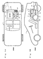
- FIG. 5 is a plan view showing a primary part of a hybrid vehicle to which an air-intaking and exhausting apparatus in an air cooling system according to the present invention is preferably mounted.
- an engine 1 mounted in a front section of the hybrid vehicle V comprises a three-cylinder internal combustion engine 2, a motor generator 3 directly joined to the engine 2 for complementing its output, and a transmission 4.
- the output of the engine 1 is transmitted by a shaft 5 to a pair of front wheels 6 and 7.
- a first battery 8 is provided for supplying an ignition unit of the engine 2 and a lighting unit with an electricity of, for example, rated 12 volts DC.
- a PDU 9 for driving the motor generator 3
- a down-converter 10 for transmitting regenerated current generated by the motor generator 3 to the first battery 8
- a second battery 11 provided as a power source for the motor generator 3.
- the second battery 11 may be of a Ni-MH type with rated 144 volts.
- the down-converter 10 and the first battery 8 are electrically connected to each other by a single-phase cable 12 while the motor generator 3 and the PDU 9 are electrically connected by a three-phase (high-pressure) cable 13.
- a pair of rear wheels 14 and 15 is mounted at both, left and right, sides in the rear section of the vehicle V.
- a direct current supplied from the second battery 11 is converted to a three-phase alternate current by an inverter in the PDU 9 and then supplied to the motor generator 3.
- the motor generator 3 is joined to a crank shaft of the engine 2 as arranged for, when energized, driving and complementing the driving force of the engine 2 or, when driven by the engine 2 running in idling mode, generating an electricity which is stored in the first battery 8.
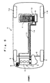
- Fig. 1A is a schematic plan view of the bottom of a vehicle equipped with the air-intaking and exhausting apparatus in the air-cooling system for the PDU and the down-converter according to the present invention.
- Fig. 1B is a schematic side view of a primary part of the present invention seen through a side body of the vehicle.
- a fuel tank 17, an exhaust pipe 18 connected to the engine 2, and a silencer 19 connected to the exhaust pipe 18 are mounted beneath a floor 16 of the rear section of the vehicle V.
- An air inlet 21 for the air cooling system in the floor 16 is located above the fuel tank 17.
- the air inlet 21 is fluidly communicated with an air cooler 23 for the PDU and the down-converter.
- the fuel tank 17 has an appropriate shape, e.g. a polyhedron or a convex polyhedron, corresponding to the configuration of the floor 16 located at the opposite side.
- the space between a slope 16a of the floor 16 and the fuel tank 17 is contemplated to have a non-uniform width and a bent.
- the air cooler 23 is linked to a fan 24, such as a sirocco fan, which is designed for turning the direction of the flow of incoming air substantially 90 degrees and connected via a tube 25 to an exhaust outlet 26 located above the silencer 19.
- the air inlet 21 and the exhaust outlet 26 open towards the lower side.
- the air cooling system has a right triangle shape comprising a first duct module including the air cooler 23 and a tube 22 extending substantially in parallel with the vehicle V and a second duct module including the tube 25 which is bent at substantially a right angle at the fan 24.
- the air inlet 21 and the exhaust outlet 26 are provided at two vertices of the right triangle shape respectively.
- the first and second duct assemblies are placed on substantially a horizontal plane.
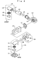
- the air inlet 21 may incorporate a maintenance lid 31 of the fuel tank.
- the maintenance lid 31 is fixedly mounted by e.g. screws to about the opening of the floor 16.
- a flange 32 is placed on the top of the maintenance lid 31 and joined via a mesh screen 33 to a tube 34,
- the flange 32, the screen 33, and the tube 34 constitute in a combination a tube assembly 35.
- the tube 34 is connected by an annular spring 36 to a duct assembly 39 consisting mainly of a duct 37 and a ring duct seal 38.
- the duct assembly 39 is connected to a heat sink case 40 in the down converter and the PDU which will be described later.
- the outlet of the heat sink case 40 is connected by a grommet 41 to a fan assembly 42 such as a sirocco fan.
- the outlet of the fan assembly 42 is turned 90 degrees from the inlet and is further connected by a spring 43 to a tube 44.
- the tube 44 is connected by an annular spring 45 to a duct 46 and then by another annular spring 47 to a tube 48.
- the exit of the tube 48 is fixedly joined to a screen 49 and a flange 50.
- the tube 48, the screen 49, and the flange 50 constitute a tube assembly 51.
- the flange 50 is tightened by e.g. screws to the opening of the floor 16.
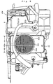
- Fig. 3 is a front view of the air cooler 23 sandwiched between the PDU 9 and the down converter 10.
- Fig. 4 is an exploded perspective view showing the positional relationship between the PDU 9 and the heat sink case 40.
- a power module PM comprises the air cooler 23 located at the center and the PDU 9 and the down converter 10 disposed on both sides of the air cooler 23.
- the PDU 9 includes a power module body (IPM) 62 consisting of semiconductor switches, a large-size capacitor 64, and a controller 66 for the IPM 62, as shown in Fig. 4.
- IPM power module body
- the air cooler 23 includes the heat sink case 40, a first heat sink 401 for the PDU 9, and a second heat sink 402 for the down converter 10.
- the first heat sink 401 comprises wave-like fins brazed to a plate 403 of the PDU 9.
- the second heat sink 402 comprises wave-like fins brazed to a plate of the down converter 10.
- the two groups of the wave-like fins are arranged with their lengths of pitch equal to each other; particularly, the height H1 of the fins of the first heat sink 401 is higher than the height H2 of the fins of the second heat sink 402.
- the two heights H1 and H2 are not identical because the PDU 9 and the down converter 10 are different in the generation of heat.
- the two groups of the fins are identical in the length of pitch in order to allow the flow of cooling air to be not biased but uniform when running through the fins.
- the other components of the PDU 9 are secured directly or indirectly to the plate 403 of the first heat sink 401 while the other components of the down converter 10 are secured to the plate of the second heat sink 402.
- the two plates of the first 401 and the second heat sink 402 are directly joined and tightened to one side of the heat sink case 40 of a box-like shape so that their fins are appropriatelypositioned in the heat sink case 40.
- the plate 403 is tightened by bolts (not shown) to the heat sink case 40 together with a holder 61 of the capacitor.
- the duct assembly 39 is located before the heat sink case 40.
- the flow of air is introduced from an opening 39A in the duct assembly 39 into the first heat sink 401 and the second heat sink 402.
- the duct assembly 39 hence has the tube 34 provided for intaking the flow of air from the outside of the vehicle V.
- the grommet 41 is connected to the other side of the heat sink case 40 or the opposite side to the duct assembly 39 for discharging the flow of air from the heat sink case 40.
- the IPM 62 having a base of a radiator sheet (e.g. a copper strip) is seated on a central region of the plate 403 of the first heat sink 401 mounted to one side of the heat sink case 40.
- the IPM 62 is covered with an IPM case 63 on which the capacitor 64 supported by the holder 61 is placed.
- the controller 66 is anchored by a stay 65 onto the holder 61 of the capacitor 64.
- the air inlet 21 of the air cooling system in the embodiment is located closely above the fuel tank 17, hence hardly permitting any object such as a cobble stone jumping from the road surface to straightforwardly enter the air inlet 21. Accordingly, the air inlet 21 can be prevented from being injured or choked with such an object. In case of running in the snow, adhesion of snow to the screen 33 of the air inlet 21 can also be avoided. The air inlet 21 will thus be prevented from being narrowed or blocked with frozen snow. Also, the exhaust outlet 26 is located closely above the silencer 19 and can hence be prevented from being frozen and reduced in the cross section by the escape of heat from the silencer 19.
- the floor 16 is commonly made of a highly heat conductive material such as aluminum and when a higher temperature condition e.g. during the summer, can thus be cooled to a lower temperature than the outside by the cooling action in the interior of the vehicle. This allows the flow of air running from a passage between the floor 16 and the fuel tank 17 to the air inlet 21 to be effectively cooled by the lower temperature of the floor 16, hence improving the efficiency of action of the air cooler for the PDU and the down converter.
- the fan 24 enables to shift the direction of the flow of air substantially 90 degrees while running from the inlet to the outlet.
- the shift of the direction of the flow of air through 90 degrees may be carried out by, for example, a sirocco fan without provision of the tubing.
- This allows the air cooling system of a right triangle shape to be economical and versatile for use in any vehicle.
- the air inlet 21 and the exhaust outlet 26 are provided at two vertices of the right triangle shape defined by the first duct assembly of the tube 22 and the air cooler 23 and the second duct assembly of the tube 25 bent to substantially a right angle at the fan 24. This permits the space (distance) between the air inlet 21 and the exhaust outlet 26 to be maximized.
- exhaust gas from the exhaust outlet 26 will hardly be sucked into the air inlet 21 e.g. in the idling mode.
- the cooling action of the air cooler 23 will thus hardly be offset by a flow of warm air from the heated exhaust gas.
- heat generated by the PDU and the down converter during the idling can effectively be dissipated by the cooling action.
- the mesh screen 33 is mounted in the air inlet 21 and enables to filter any object of greater than the mesh size which is thus disallowed to enter the air cooler 23.
- the mesh screen 33 prevents the fins of the heat sink from being broken and blocked, thus maintaining the cooling effect of the heat sink.
- the air cooling system of the present invention is mounted on the floor 16 of a vehicle while its air inlet 21 and exhaust output 26 open downwardly of the vehicle or face against the road surface and stay out of sight behind the vehicle body. This contributes to the improvement in the respect of vehicle design.
- the present invention provides the following advantages:
Landscapes
- Engineering & Computer Science (AREA)
- Chemical & Material Sciences (AREA)
- Combustion & Propulsion (AREA)
- Transportation (AREA)
- Mechanical Engineering (AREA)
- Cooling, Air Intake And Gas Exhaust, And Fuel Tank Arrangements In Propulsion Units (AREA)
- Electric Propulsion And Braking For Vehicles (AREA)
- Hybrid Electric Vehicles (AREA)
- Arrangement Or Mounting Of Propulsion Units For Vehicles (AREA)
- Cooling Or The Like Of Electrical Apparatus (AREA)
Claims (8)
- Dispositif d'admission et d'évacuation d'air dans un système de refroidissement par air destiné à un bloc de puissance (9) et à un convertisseur-abaisseur de tension (10) comprenant :une entrée d'air (21) disposée dans le fond d'un véhicule pour s'ouvrir vers le bas,un dispositif de refroidissement par air (23) destiné au bloc de puissance (9) et au convertisseur-abaisseur de tension (10), relié par un premier tube (22) à l'entrée d'air (21), etune sortie d'évacuation (26) disposée pour s'ouvrir vers le bas et reliée par un second tube (25) au dispositif de refroidissement par air (23), oùle premier tube (22) et le second tube (25) sont placés sur un plan horizontal et s'étendent de façon orthogonale l'un par rapport à l'autre.
- Dispositif d'admission et d'évacuation d'air dans un système de refroidissement par air destiné à un bloc de puissance (9) et à un convertisseur-abaisseur de tension (10) selon la revendication 1, dans lequel au moins une partie de l'entrée d'air (21) est en vis-à-vis de la partie supérieure d'un réservoir de carburant (17).
- Dispositif d'admission et d'évacuation d'air dans un système de refroidissement par air destiné à un bloc de puissance (9) et à un convertisseur-abaisseur de tension (10) selon la revendication 1 ou 2, comprenant en outre un plancher (16) constitué principalement d'une partie horizontale et d'une partie inclinée (16a), qui est situé au fond du véhicule, et où l'espace entre le plancher (16) et le réservoir de carburant (17) monté à proximité du plancher est envisagé comme ayant une largeur non uniforme et une partie courbée en vue d'empêcher au moins un objet de la surface de la route d'entrer directement dans l'entrée d'air (21).
- Dispositif d'admission et d'évacuation d'air dans un système de refroidissement par air destiné à un bloc de puissance (9) et à un convertisseur-abaisseur de tension (10) selon la revendication 1, dans lequel le dispositif de refroidissement par air (23) comprend un ventilateur (24) destiné à faire entrer et à faire sortir la circulation d'air pour refroidir le bloc de puissance (9) et le convertisseur-abaisseur de tension (10), et le ventilateur (24) est conçu pour faire tourner la direction de la circulation d'air de pratiquement 90 degrés.
- Dispositif d'admission et d'évacuation d'air dans un système de refroidissement par air destiné à un bloc de puissance (9) et à un convertisseur-abaisseur de tension (10) selon la revendication 4, dans lequel le ventilateur (24) est un ventilateur de type sirocco.
- Dispositif d'admission et d'évacuation d'air dans un système de refroidissement par air destiné à un bloc de puissance (9) et à un convertisseur-abaisseur de tension (10) selon la revendication 1, dans lequel la sortie d'évacuation (26) est située au-dessus d'un silencieux (19) relié au tuyau d'échappement.
- Dispositif d'admission et d'évacuation d'air dans un système de refroidissement par air destiné à un bloc de puissance (9) et à un convertisseur-abaisseur de tension (10) selon la revendication 1, dans lequel, dans une observation dans une direction d'avance du véhicule, l'entrée d'air (21) est située devant la sortie d'évacuation (26) sur le véhicule.
- Dispositif d'admission et d'évacuation d'air dans un système de refroidissement par air destiné à un bloc de puissance (9) et à un convertisseur-abaisseur de tension (10) selon la revendication 1, dans lequel au moins soit l'entrée d'air (21), soit la sortie d'évacuation (26) comporte une grille à mailles (33) adaptée dans celle-ci.
Applications Claiming Priority (2)
| Application Number | Priority Date | Filing Date | Title |
|---|---|---|---|
| JP19103799 | 1999-07-05 | ||
| JP19103799A JP3369514B2 (ja) | 1999-07-05 | 1999-07-05 | Pduとダウンバータの空冷システムにおける吸排気系装置 |
Publications (3)
| Publication Number | Publication Date |
|---|---|
| EP1067006A2 EP1067006A2 (fr) | 2001-01-10 |
| EP1067006A3 EP1067006A3 (fr) | 2003-01-08 |
| EP1067006B1 true EP1067006B1 (fr) | 2004-04-14 |
Family
ID=16267849
Family Applications (1)
| Application Number | Title | Priority Date | Filing Date |
|---|---|---|---|
| EP00113122A Expired - Lifetime EP1067006B1 (fr) | 1999-07-05 | 2000-06-28 | Dispositif d'admission et d'évacuation d'air dans des systèmes de refroidissment à l air de l'unité d'entraínement et du convertisseur-abaisseur de tension |
Country Status (5)
| Country | Link |
|---|---|
| US (1) | US6457542B1 (fr) |
| EP (1) | EP1067006B1 (fr) |
| JP (1) | JP3369514B2 (fr) |
| CA (1) | CA2310797C (fr) |
| DE (1) | DE60009800T2 (fr) |
Cited By (1)
| Publication number | Priority date | Publication date | Assignee | Title |
|---|---|---|---|---|
| CN100585140C (zh) * | 2007-07-05 | 2010-01-27 | 力帆实业(集团)股份有限公司 | 汽油机导风罩与燃油箱组件 |
Families Citing this family (45)
| Publication number | Priority date | Publication date | Assignee | Title |
|---|---|---|---|---|
| JP4421759B2 (ja) * | 2000-10-26 | 2010-02-24 | 本田技研工業株式会社 | 自動車用パワードライブユニットの冷却構造 |
| JP3652634B2 (ja) | 2001-10-05 | 2005-05-25 | 本田技研工業株式会社 | 高圧電装部品の冷却構造 |
| DE10317580B4 (de) * | 2002-04-18 | 2010-09-16 | Hitachi, Ltd. | Elektrische Wechselrichtervorrichtung mit einem Flüssigkeitskanal sowie Elektrofahrzeug mit einer derartigen Wechselrichtervorrichtung |
| US7025159B2 (en) * | 2003-09-12 | 2006-04-11 | Ford Global Technologies, Llc | Cooling system for a vehicle battery |
| JP3784813B2 (ja) * | 2003-11-26 | 2006-06-14 | 本田技研工業株式会社 | 車両モータ用高圧電装の冷却装置及びハイブリッド車両 |
| JP4285405B2 (ja) * | 2004-12-17 | 2009-06-24 | 日産自動車株式会社 | ハイブリッド自動車 |
| JP4385020B2 (ja) * | 2005-06-02 | 2009-12-16 | 本田技研工業株式会社 | 車両用電源装置 |
| JP4611820B2 (ja) * | 2005-07-04 | 2011-01-12 | 本田技研工業株式会社 | 車両用電装ユニットの冷却装置 |
| JP4415910B2 (ja) | 2005-07-12 | 2010-02-17 | トヨタ自動車株式会社 | ハイブリッド車両の構造 |
| KR100802767B1 (ko) * | 2005-11-04 | 2008-02-12 | 현대자동차주식회사 | 하이브리드 차량의 배터리유닛 및 모터제어유닛 냉각시스템 |
| WO2007111659A2 (fr) * | 2005-12-08 | 2007-10-04 | Polaris Industries Inc. | Motocycle automatique |
| JP4812529B2 (ja) * | 2006-06-14 | 2011-11-09 | トヨタ自動車株式会社 | 電源装置および車両 |
| EP1897739B1 (fr) * | 2006-09-07 | 2010-11-03 | Honda Motor Co., Ltd. | Structure de refroidissement de dispositif électrique dans un véhicule |
| JP4832225B2 (ja) * | 2006-09-07 | 2011-12-07 | 本田技研工業株式会社 | 車両における電気機器の冷却構造 |
| US8495890B2 (en) * | 2007-01-22 | 2013-07-30 | Johnson Controls Technology Company | Cooling member |
| US8014110B2 (en) * | 2007-01-22 | 2011-09-06 | Johnson Controls Technology Company | Variable speed drive with integral bypass contactor |
| US8149579B2 (en) * | 2008-03-28 | 2012-04-03 | Johnson Controls Technology Company | Cooling member |
| US20080242211A1 (en) * | 2007-03-30 | 2008-10-02 | Franz Winter | High voltage battery with a pulling ventilator in a fuel cell vehicle |
| KR100992747B1 (ko) * | 2007-07-13 | 2010-11-05 | 기아자동차주식회사 | 하이브리드 차량용 고전압 전장부품의 냉각장치 |
| JP4283326B1 (ja) * | 2007-12-25 | 2009-06-24 | 本田技研工業株式会社 | バッテリの冷却風取入構造 |
| US9924631B2 (en) | 2008-04-22 | 2018-03-27 | George E. Alliss | Spool for straight through line feed vegetation trimmer apparatus with modules and spokes |
| US20090309082A1 (en) * | 2008-06-11 | 2009-12-17 | Warn Industries, Inc. | Fan Cooled Winch |
| US7946368B2 (en) * | 2008-07-14 | 2011-05-24 | Deere & Company | Agricultural machine having dedicated multi-section fan unit |
| JP4919102B2 (ja) * | 2008-11-17 | 2012-04-18 | 本田技研工業株式会社 | 車両用電源ユニットの冷却構造 |
| JP5360689B2 (ja) * | 2009-09-24 | 2013-12-04 | スズキ株式会社 | 車両の高電圧ケーブルの配策構造 |
| JP5024353B2 (ja) * | 2009-10-29 | 2012-09-12 | トヨタ自動車株式会社 | 電気機器の冷却システム |
| US8982586B2 (en) * | 2010-12-23 | 2015-03-17 | Caterpillar Inc. | Method for regulating temperature of transistor-based component |
| US8365858B2 (en) * | 2010-12-27 | 2013-02-05 | Mazda Motor Corporation | Harness arrangement structure of vehicle |
| JP5473954B2 (ja) * | 2011-01-14 | 2014-04-16 | 本田技研工業株式会社 | 冷却構造を有する高電圧機器装置、及びそれを備えた車両 |
| US8950533B2 (en) * | 2011-01-31 | 2015-02-10 | GM Global Technology Operations LLC | Cooling arrangement for a component in a vehicle |
| FR2972143B1 (fr) * | 2011-03-01 | 2013-09-20 | Renault Sa | Systeme de liaison d'une batterie d'alimentation d'un vehicule automobile |
| JP2012183903A (ja) | 2011-03-04 | 2012-09-27 | Suzuki Motor Corp | 車両の高圧ケーブル配索構造 |
| JP5716964B2 (ja) * | 2011-09-12 | 2015-05-13 | 株式会社オートネットワーク技術研究所 | 冷却装置 |
| US8955630B2 (en) * | 2011-12-14 | 2015-02-17 | Honda Motor Co., Ltd. | Symbiotic engine intake system and battery box |
| FR2987702A1 (fr) * | 2012-03-02 | 2013-09-06 | Peugeot Citroen Automobiles Sa | Conduit de ventilation pour un module de batteries de vehicule hybride ou electrique |
| US8876119B2 (en) * | 2012-09-04 | 2014-11-04 | Caterpillar Inc. | Grommet and seal assembly for cooling pipes passing through sound wall |
| CN104041203B (zh) * | 2013-01-08 | 2015-08-05 | 株式会社小松制作所 | 蓄电池式作业机械以及蓄电池式叉车 |
| WO2015149287A1 (fr) * | 2014-04-01 | 2015-10-08 | 深圳市智轮电动车驱动技术有限公司 | Système de commande de température de véhicule électrique |
| US9822752B2 (en) * | 2014-05-19 | 2017-11-21 | Ford Global Technologies, Llc | Vehicle heating system and method |
| USD970321S1 (en) | 2014-11-20 | 2022-11-22 | Torvent Llc | Line trimmer component |
| JP6326007B2 (ja) * | 2015-06-12 | 2018-05-16 | 株式会社Subaru | 車載二次電池の冷却装置 |
| JP2017171176A (ja) * | 2016-03-24 | 2017-09-28 | トヨタ自動車株式会社 | 車載バッテリの冷却システム |
| JP6631565B2 (ja) * | 2017-03-08 | 2020-01-15 | トヨタ自動車株式会社 | 車両のダクト構造 |
| EP3670223B1 (fr) * | 2018-12-21 | 2022-06-29 | Valeo Autosystemy SP. Z.O.O. | Système de chauffage, de ventilation et de conditionnement d'air |
| JP7563885B2 (ja) * | 2020-03-04 | 2024-10-08 | 本田技研工業株式会社 | 車両 |
Family Cites Families (14)
| Publication number | Priority date | Publication date | Assignee | Title |
|---|---|---|---|---|
| US4934449A (en) * | 1988-06-15 | 1990-06-19 | J. I. Case Company | Air intake system for an agricultural implement |
| US5082075A (en) * | 1989-09-07 | 1992-01-21 | Globe-Union Inc. | Method and apparatus for thermal control of automotive components |
| US5031712A (en) * | 1989-09-07 | 1991-07-16 | Globe-Union, Inc. | Method and apparatus for thermal control of automotive components |
| JP3125198B2 (ja) * | 1991-12-04 | 2001-01-15 | 本田技研工業株式会社 | 電気自動車におけるバッテリ温度制御装置 |
| US5193608A (en) * | 1992-03-25 | 1993-03-16 | Toyo Radiator Co., Ltd. | Radiator with fan for motor vehicles |
| JPH07194139A (ja) * | 1993-12-27 | 1995-07-28 | Hitachi Ltd | 電気自動車用インバータの冷却装置 |
| US5427502A (en) * | 1994-03-28 | 1995-06-27 | Deere & Company | Fan shroud aspirator |
| US5588482A (en) * | 1994-09-26 | 1996-12-31 | Ford Motor Company | Ducted cooling system for an automotive vehicle |
| US5542489A (en) * | 1995-05-31 | 1996-08-06 | Ford Motor Company | Battery thermal chamber |
| US6029762A (en) * | 1997-01-22 | 2000-02-29 | Textron Inc. | Battery warmer for extending the range of an electrically powered vehicle |
| DE59808905D1 (de) * | 1998-04-07 | 2003-08-07 | Swatch Group Man Services Ag B | Einrichtung zur Kühlung von Antriebseinheiten und zur Innenraumbeheizung eines Hybridfahrzeuges |
| US6167976B1 (en) * | 1998-07-30 | 2001-01-02 | Deere & Company | Engine enclosure |
| US6237357B1 (en) * | 1999-06-07 | 2001-05-29 | Mitsubishi Heavy Industries, Ltd. | Vehicular air conditioner using heat pump |
| US6152096A (en) * | 1999-07-06 | 2000-11-28 | Visteon Global Technologies, Inc. | Storage battery protection by engine air intake system |
-
1999
- 1999-07-05 JP JP19103799A patent/JP3369514B2/ja not_active Expired - Fee Related
-
2000
- 2000-06-07 CA CA002310797A patent/CA2310797C/fr not_active Expired - Fee Related
- 2000-06-28 EP EP00113122A patent/EP1067006B1/fr not_active Expired - Lifetime
- 2000-06-28 DE DE60009800T patent/DE60009800T2/de not_active Expired - Fee Related
- 2000-07-03 US US09/609,649 patent/US6457542B1/en not_active Expired - Fee Related
Cited By (1)
| Publication number | Priority date | Publication date | Assignee | Title |
|---|---|---|---|---|
| CN100585140C (zh) * | 2007-07-05 | 2010-01-27 | 力帆实业(集团)股份有限公司 | 汽油机导风罩与燃油箱组件 |
Also Published As
| Publication number | Publication date |
|---|---|
| US6457542B1 (en) | 2002-10-01 |
| CA2310797A1 (fr) | 2001-01-05 |
| DE60009800D1 (de) | 2004-05-19 |
| EP1067006A2 (fr) | 2001-01-10 |
| DE60009800T2 (de) | 2005-03-31 |
| CA2310797C (fr) | 2003-08-05 |
| EP1067006A3 (fr) | 2003-01-08 |
| JP2001018664A (ja) | 2001-01-23 |
| JP3369514B2 (ja) | 2003-01-20 |
Similar Documents
| Publication | Publication Date | Title |
|---|---|---|
| EP1067006B1 (fr) | Dispositif d'admission et d'évacuation d'air dans des systèmes de refroidissment à l air de l'unité d'entraínement et du convertisseur-abaisseur de tension | |
| US7049707B2 (en) | Auxiliary power unit for a diesel powered transport vehicle | |
| US7245033B2 (en) | Auxiliary heating and air conditioning unit for a diesel powered transport vehicle | |
| US7291932B2 (en) | Auxiliary power unit for a diesel powered transport vehicle | |
| KR100992747B1 (ko) | 하이브리드 차량용 고전압 전장부품의 냉각장치 | |
| US5631821A (en) | Cooling system for electric vehicle inverter system | |
| US7079379B2 (en) | Cooling device high voltage electrical unit for motor of vehicle, and hybrid vehicle | |
| EP2180776B1 (fr) | Ensemble d'inverseur automobile | |
| US7051825B2 (en) | Structure for installing high-voltage equipment component to vehicle | |
| US7819172B2 (en) | Cooling apparatus for vehicle electrical packaging unit | |
| US6188574B1 (en) | Cooling structure for electric vehicle | |
| US20070114083A1 (en) | Vehicle power supply system | |
| WO2020123351A1 (fr) | Machine électrique périmétrique refroidie par liquide et onduleur intégré | |
| KR101964354B1 (ko) | 자동차 | |
| JP4321006B2 (ja) | 電池システムおよび冷却構造 | |
| JP2005138792A (ja) | ハイブリッド自動車の実装構造 | |
| JP3440724B2 (ja) | 移動電源車 | |
| US20250229653A1 (en) | Stationary inductive charging device | |
| JP4239474B2 (ja) | 車輌用駆動装置 | |
| JP7460960B2 (ja) | レンジエクステンダ車両用発電ユニットの冷却構造 | |
| EP3626492B1 (fr) | Unité de conditionnement encastrable | |
| US11362016B2 (en) | Transaxle with semiconductor device cooling arrangement | |
| CN107420191A (zh) | 用于移动应用的发电设备 | |
| CN114643856A (zh) | 用于氢电动卡车的冷却组件 | |
| CN113103945A (zh) | 一种增程式冷链物流车散热装置 |
Legal Events
| Date | Code | Title | Description |
|---|---|---|---|
| PUAI | Public reference made under article 153(3) epc to a published international application that has entered the european phase |
Free format text: ORIGINAL CODE: 0009012 |
|
| 17P | Request for examination filed |
Effective date: 20000628 |
|
| AK | Designated contracting states |
Kind code of ref document: A2 Designated state(s): AT BE CH CY DE DK ES FI FR GB GR IE IT LI LU MC NL PT SE |
|
| AX | Request for extension of the european patent |
Free format text: AL;LT;LV;MK;RO;SI |
|
| PUAL | Search report despatched |
Free format text: ORIGINAL CODE: 0009013 |
|
| AK | Designated contracting states |
Kind code of ref document: A3 Designated state(s): AT BE CH CY DE DK ES FI FR GB GR IE IT LI LU MC NL PT SE |
|
| AX | Request for extension of the european patent |
Free format text: AL;LT;LV;MK;RO;SI |
|
| AKX | Designation fees paid |
Designated state(s): DE FR GB |
|
| GRAP | Despatch of communication of intention to grant a patent |
Free format text: ORIGINAL CODE: EPIDOSNIGR1 |
|
| RIN1 | Information on inventor provided before grant (corrected) |
Inventor name: HASEGAWA, OSAMU Inventor name: HOSONO, YOSHIO Inventor name: AMAKAI, MASAKI Inventor name: OGAWA, TAICHI Inventor name: TAKEMOTO, HIDEHARU Inventor name: OHTSU, AKIHITO |
|
| GRAS | Grant fee paid |
Free format text: ORIGINAL CODE: EPIDOSNIGR3 |
|
| GRAA | (expected) grant |
Free format text: ORIGINAL CODE: 0009210 |
|
| AK | Designated contracting states |
Kind code of ref document: B1 Designated state(s): DE FR GB |
|
| REG | Reference to a national code |
Ref country code: GB Ref legal event code: FG4D |
|
| REF | Corresponds to: |
Ref document number: 60009800 Country of ref document: DE Date of ref document: 20040519 Kind code of ref document: P |
|
| REG | Reference to a national code |
Ref country code: IE Ref legal event code: FG4D |
|
| ET | Fr: translation filed | ||
| PLBE | No opposition filed within time limit |
Free format text: ORIGINAL CODE: 0009261 |
|
| STAA | Information on the status of an ep patent application or granted ep patent |
Free format text: STATUS: NO OPPOSITION FILED WITHIN TIME LIMIT |
|
| 26N | No opposition filed |
Effective date: 20050117 |
|
| REG | Reference to a national code |
Ref country code: IE Ref legal event code: MM4A |
|
| PGFP | Annual fee paid to national office [announced via postgrant information from national office to epo] |
Ref country code: FR Payment date: 20050608 Year of fee payment: 6 |
|
| PGFP | Annual fee paid to national office [announced via postgrant information from national office to epo] |
Ref country code: GB Payment date: 20060628 Year of fee payment: 7 |
|
| REG | Reference to a national code |
Ref country code: FR Ref legal event code: ST Effective date: 20070228 |
|
| GBPC | Gb: european patent ceased through non-payment of renewal fee |
Effective date: 20070628 |
|
| PG25 | Lapsed in a contracting state [announced via postgrant information from national office to epo] |
Ref country code: FR Free format text: LAPSE BECAUSE OF NON-PAYMENT OF DUE FEES Effective date: 20060630 |
|
| PG25 | Lapsed in a contracting state [announced via postgrant information from national office to epo] |
Ref country code: GB Free format text: LAPSE BECAUSE OF NON-PAYMENT OF DUE FEES Effective date: 20070628 |
|
| PGFP | Annual fee paid to national office [announced via postgrant information from national office to epo] |
Ref country code: DE Payment date: 20080703 Year of fee payment: 9 |
|
| PG25 | Lapsed in a contracting state [announced via postgrant information from national office to epo] |
Ref country code: DE Free format text: LAPSE BECAUSE OF NON-PAYMENT OF DUE FEES Effective date: 20100101 |