EP1065023A2 - Laserbearbeitungsverfahren, Verfahren zur Herstellung eines Tintenstrahlaufzeichnungskopfes mittels eines solchen Herstllungsverfahren, und mittels eines solchen Herstellungserfahrens hergestellter Tintenstrahlaufzeichnungskopf - Google Patents
Laserbearbeitungsverfahren, Verfahren zur Herstellung eines Tintenstrahlaufzeichnungskopfes mittels eines solchen Herstllungsverfahren, und mittels eines solchen Herstellungserfahrens hergestellter Tintenstrahlaufzeichnungskopf Download PDFInfo
- Publication number
- EP1065023A2 EP1065023A2 EP00113699A EP00113699A EP1065023A2 EP 1065023 A2 EP1065023 A2 EP 1065023A2 EP 00113699 A EP00113699 A EP 00113699A EP 00113699 A EP00113699 A EP 00113699A EP 1065023 A2 EP1065023 A2 EP 1065023A2
- Authority
- EP
- European Patent Office
- Prior art keywords
- ink
- laser
- laser beam
- recording head
- jet recording
- Prior art date
- Legal status (The legal status is an assumption and is not a legal conclusion. Google has not performed a legal analysis and makes no representation as to the accuracy of the status listed.)
- Withdrawn
Links
- 238000000034 method Methods 0.000 title claims abstract description 146
- 238000003672 processing method Methods 0.000 title claims abstract description 74
- 238000004519 manufacturing process Methods 0.000 title claims description 80
- 238000012545 processing Methods 0.000 claims abstract description 150
- 239000011347 resin Substances 0.000 claims abstract description 79
- 229920005989 resin Polymers 0.000 claims abstract description 79
- 230000005855 radiation Effects 0.000 claims abstract description 75
- 230000008569 process Effects 0.000 claims abstract description 56
- 230000002123 temporal effect Effects 0.000 claims abstract description 43
- 239000006227 byproduct Substances 0.000 claims abstract description 16
- 238000000608 laser ablation Methods 0.000 claims abstract description 11
- 239000000463 material Substances 0.000 claims description 182
- 239000007788 liquid Substances 0.000 claims description 82
- 238000000859 sublimation Methods 0.000 claims description 40
- 230000008022 sublimation Effects 0.000 claims description 40
- 238000007599 discharging Methods 0.000 claims description 36
- 229910052710 silicon Inorganic materials 0.000 claims description 29
- 239000011521 glass Substances 0.000 claims description 21
- 230000015572 biosynthetic process Effects 0.000 claims description 19
- 230000006835 compression Effects 0.000 claims description 13
- 238000007906 compression Methods 0.000 claims description 13
- 239000006185 dispersion Substances 0.000 claims description 12
- 230000001678 irradiating effect Effects 0.000 claims description 12
- 230000001902 propagating effect Effects 0.000 claims description 12
- 239000007769 metal material Substances 0.000 claims description 10
- 229910010272 inorganic material Inorganic materials 0.000 claims description 9
- 229910052500 inorganic mineral Inorganic materials 0.000 claims description 8
- 239000011707 mineral Substances 0.000 claims description 8
- 230000001360 synchronised effect Effects 0.000 claims description 8
- 238000002156 mixing Methods 0.000 claims description 7
- 150000001875 compounds Chemical class 0.000 claims description 6
- 150000002484 inorganic compounds Chemical class 0.000 claims description 6
- 239000012780 transparent material Substances 0.000 claims description 6
- 238000009834 vaporization Methods 0.000 claims description 4
- 230000008016 vaporization Effects 0.000 claims description 4
- 230000008020 evaporation Effects 0.000 claims description 2
- 238000001704 evaporation Methods 0.000 claims description 2
- 235000021251 pulses Nutrition 0.000 description 104
- 229920002492 poly(sulfone) Polymers 0.000 description 40
- 238000002679 ablation Methods 0.000 description 33
- 230000003287 optical effect Effects 0.000 description 21
- XUIMIQQOPSSXEZ-UHFFFAOYSA-N Silicon Chemical compound [Si] XUIMIQQOPSSXEZ-UHFFFAOYSA-N 0.000 description 20
- 239000010703 silicon Substances 0.000 description 20
- 239000003086 colorant Substances 0.000 description 16
- 239000000872 buffer Substances 0.000 description 11
- 238000005530 etching Methods 0.000 description 10
- 239000000919 ceramic Substances 0.000 description 9
- 230000010355 oscillation Effects 0.000 description 9
- 239000010408 film Substances 0.000 description 8
- 229910052751 metal Inorganic materials 0.000 description 7
- 239000002184 metal Substances 0.000 description 7
- 238000010521 absorption reaction Methods 0.000 description 6
- 230000004907 flux Effects 0.000 description 6
- 239000011295 pitch Substances 0.000 description 6
- 239000004065 semiconductor Substances 0.000 description 6
- 238000012546 transfer Methods 0.000 description 6
- RYGMFSIKBFXOCR-UHFFFAOYSA-N Copper Chemical compound [Cu] RYGMFSIKBFXOCR-UHFFFAOYSA-N 0.000 description 5
- 229910052782 aluminium Inorganic materials 0.000 description 5
- XAGFODPZIPBFFR-UHFFFAOYSA-N aluminium Chemical compound [Al] XAGFODPZIPBFFR-UHFFFAOYSA-N 0.000 description 5
- 239000011365 complex material Substances 0.000 description 5
- 230000003750 conditioning effect Effects 0.000 description 5
- 239000007791 liquid phase Substances 0.000 description 5
- 239000004642 Polyimide Substances 0.000 description 4
- 230000027455 binding Effects 0.000 description 4
- 239000011889 copper foil Substances 0.000 description 4
- 238000005520 cutting process Methods 0.000 description 4
- 239000000975 dye Substances 0.000 description 4
- 230000006870 function Effects 0.000 description 4
- 230000035515 penetration Effects 0.000 description 4
- 239000012071 phase Substances 0.000 description 4
- 229920001721 polyimide Polymers 0.000 description 4
- 239000010453 quartz Substances 0.000 description 4
- 238000010008 shearing Methods 0.000 description 4
- VYPSYNLAJGMNEJ-UHFFFAOYSA-N silicon dioxide Inorganic materials O=[Si]=O VYPSYNLAJGMNEJ-UHFFFAOYSA-N 0.000 description 4
- 238000003860 storage Methods 0.000 description 4
- 125000004429 atom Chemical group 0.000 description 3
- 239000001045 blue dye Substances 0.000 description 3
- 229910010293 ceramic material Inorganic materials 0.000 description 3
- 239000013078 crystal Substances 0.000 description 3
- 238000009826 distribution Methods 0.000 description 3
- 239000011147 inorganic material Substances 0.000 description 3
- 238000000059 patterning Methods 0.000 description 3
- 241000276498 Pollachius virens Species 0.000 description 2
- VFQHLZMKZVVGFQ-UHFFFAOYSA-N [F].[Kr] Chemical compound [F].[Kr] VFQHLZMKZVVGFQ-UHFFFAOYSA-N 0.000 description 2
- 230000015556 catabolic process Effects 0.000 description 2
- 238000004040 coloring Methods 0.000 description 2
- 238000006731 degradation reaction Methods 0.000 description 2
- 230000005684 electric field Effects 0.000 description 2
- 238000005516 engineering process Methods 0.000 description 2
- 230000007613 environmental effect Effects 0.000 description 2
- 210000000887 face Anatomy 0.000 description 2
- 239000000945 filler Substances 0.000 description 2
- 230000004927 fusion Effects 0.000 description 2
- 210000003128 head Anatomy 0.000 description 2
- 238000010438 heat treatment Methods 0.000 description 2
- 238000005286 illumination Methods 0.000 description 2
- 238000006552 photochemical reaction Methods 0.000 description 2
- 230000000750 progressive effect Effects 0.000 description 2
- 230000009467 reduction Effects 0.000 description 2
- 239000005871 repellent Substances 0.000 description 2
- 230000002463 transducing effect Effects 0.000 description 2
- 238000007740 vapor deposition Methods 0.000 description 2
- 235000010627 Phaseolus vulgaris Nutrition 0.000 description 1
- 244000046052 Phaseolus vulgaris Species 0.000 description 1
- -1 SUS Chemical class 0.000 description 1
- 238000002835 absorbance Methods 0.000 description 1
- 238000009825 accumulation Methods 0.000 description 1
- PNEYBMLMFCGWSK-UHFFFAOYSA-N aluminium oxide Inorganic materials [O-2].[O-2].[O-2].[Al+3].[Al+3] PNEYBMLMFCGWSK-UHFFFAOYSA-N 0.000 description 1
- 238000004380 ashing Methods 0.000 description 1
- 230000008901 benefit Effects 0.000 description 1
- 230000005540 biological transmission Effects 0.000 description 1
- 125000004432 carbon atom Chemical group C* 0.000 description 1
- 238000003486 chemical etching Methods 0.000 description 1
- 238000006243 chemical reaction Methods 0.000 description 1
- 239000011248 coating agent Substances 0.000 description 1
- 238000000576 coating method Methods 0.000 description 1
- 238000007796 conventional method Methods 0.000 description 1
- 229910052802 copper Inorganic materials 0.000 description 1
- 239000010949 copper Substances 0.000 description 1
- 238000012937 correction Methods 0.000 description 1
- 238000011161 development Methods 0.000 description 1
- 238000005553 drilling Methods 0.000 description 1
- 230000000694 effects Effects 0.000 description 1
- 230000002708 enhancing effect Effects 0.000 description 1
- 230000005284 excitation Effects 0.000 description 1
- 230000009477 glass transition Effects 0.000 description 1
- 229910052736 halogen Inorganic materials 0.000 description 1
- 150000002367 halogens Chemical class 0.000 description 1
- 230000000977 initiatory effect Effects 0.000 description 1
- 238000003780 insertion Methods 0.000 description 1
- 230000037431 insertion Effects 0.000 description 1
- 230000031700 light absorption Effects 0.000 description 1
- 150000002739 metals Chemical class 0.000 description 1
- 238000005459 micromachining Methods 0.000 description 1
- 230000009149 molecular binding Effects 0.000 description 1
- 238000000465 moulding Methods 0.000 description 1
- 238000001259 photo etching Methods 0.000 description 1
- 229920000642 polymer Polymers 0.000 description 1
- 239000002952 polymeric resin Substances 0.000 description 1
- 238000007639 printing Methods 0.000 description 1
- 238000001228 spectrum Methods 0.000 description 1
- 238000004528 spin coating Methods 0.000 description 1
- 238000004544 sputter deposition Methods 0.000 description 1
- 238000005092 sublimation method Methods 0.000 description 1
- 229920003002 synthetic resin Polymers 0.000 description 1
- 239000010409 thin film Substances 0.000 description 1
- 230000001131 transforming effect Effects 0.000 description 1
Images


Classifications
-
- B—PERFORMING OPERATIONS; TRANSPORTING
- B41—PRINTING; LINING MACHINES; TYPEWRITERS; STAMPS
- B41J—TYPEWRITERS; SELECTIVE PRINTING MECHANISMS, i.e. MECHANISMS PRINTING OTHERWISE THAN FROM A FORME; CORRECTION OF TYPOGRAPHICAL ERRORS
- B41J2/00—Typewriters or selective printing mechanisms characterised by the printing or marking process for which they are designed
- B41J2/005—Typewriters or selective printing mechanisms characterised by the printing or marking process for which they are designed characterised by bringing liquid or particles selectively into contact with a printing material
- B41J2/01—Ink jet
- B41J2/135—Nozzles
- B41J2/16—Production of nozzles
- B41J2/1621—Manufacturing processes
- B41J2/1632—Manufacturing processes machining
- B41J2/1634—Manufacturing processes machining laser machining
-
- B—PERFORMING OPERATIONS; TRANSPORTING
- B41—PRINTING; LINING MACHINES; TYPEWRITERS; STAMPS
- B41J—TYPEWRITERS; SELECTIVE PRINTING MECHANISMS, i.e. MECHANISMS PRINTING OTHERWISE THAN FROM A FORME; CORRECTION OF TYPOGRAPHICAL ERRORS
- B41J2/00—Typewriters or selective printing mechanisms characterised by the printing or marking process for which they are designed
- B41J2/005—Typewriters or selective printing mechanisms characterised by the printing or marking process for which they are designed characterised by bringing liquid or particles selectively into contact with a printing material
-
- B—PERFORMING OPERATIONS; TRANSPORTING
- B23—MACHINE TOOLS; METAL-WORKING NOT OTHERWISE PROVIDED FOR
- B23K—SOLDERING OR UNSOLDERING; WELDING; CLADDING OR PLATING BY SOLDERING OR WELDING; CUTTING BY APPLYING HEAT LOCALLY, e.g. FLAME CUTTING; WORKING BY LASER BEAM
- B23K26/00—Working by laser beam, e.g. welding, cutting or boring
- B23K26/02—Positioning or observing the workpiece, e.g. with respect to the point of impact; Aligning, aiming or focusing the laser beam
- B23K26/06—Shaping the laser beam, e.g. by masks or multi-focusing
- B23K26/062—Shaping the laser beam, e.g. by masks or multi-focusing by direct control of the laser beam
- B23K26/0622—Shaping the laser beam, e.g. by masks or multi-focusing by direct control of the laser beam by shaping pulses
- B23K26/0624—Shaping the laser beam, e.g. by masks or multi-focusing by direct control of the laser beam by shaping pulses using ultrashort pulses, i.e. pulses of 1ns or less
-
- B—PERFORMING OPERATIONS; TRANSPORTING
- B23—MACHINE TOOLS; METAL-WORKING NOT OTHERWISE PROVIDED FOR
- B23K—SOLDERING OR UNSOLDERING; WELDING; CLADDING OR PLATING BY SOLDERING OR WELDING; CUTTING BY APPLYING HEAT LOCALLY, e.g. FLAME CUTTING; WORKING BY LASER BEAM
- B23K26/00—Working by laser beam, e.g. welding, cutting or boring
- B23K26/02—Positioning or observing the workpiece, e.g. with respect to the point of impact; Aligning, aiming or focusing the laser beam
- B23K26/06—Shaping the laser beam, e.g. by masks or multi-focusing
- B23K26/064—Shaping the laser beam, e.g. by masks or multi-focusing by means of optical elements, e.g. lenses, mirrors or prisms
- B23K26/066—Shaping the laser beam, e.g. by masks or multi-focusing by means of optical elements, e.g. lenses, mirrors or prisms by using masks
-
- B—PERFORMING OPERATIONS; TRANSPORTING
- B23—MACHINE TOOLS; METAL-WORKING NOT OTHERWISE PROVIDED FOR
- B23K—SOLDERING OR UNSOLDERING; WELDING; CLADDING OR PLATING BY SOLDERING OR WELDING; CUTTING BY APPLYING HEAT LOCALLY, e.g. FLAME CUTTING; WORKING BY LASER BEAM
- B23K26/00—Working by laser beam, e.g. welding, cutting or boring
- B23K26/36—Removing material
- B23K26/40—Removing material taking account of the properties of the material involved
-
- B—PERFORMING OPERATIONS; TRANSPORTING
- B41—PRINTING; LINING MACHINES; TYPEWRITERS; STAMPS
- B41J—TYPEWRITERS; SELECTIVE PRINTING MECHANISMS, i.e. MECHANISMS PRINTING OTHERWISE THAN FROM A FORME; CORRECTION OF TYPOGRAPHICAL ERRORS
- B41J2/00—Typewriters or selective printing mechanisms characterised by the printing or marking process for which they are designed
- B41J2/005—Typewriters or selective printing mechanisms characterised by the printing or marking process for which they are designed characterised by bringing liquid or particles selectively into contact with a printing material
- B41J2/01—Ink jet
- B41J2/135—Nozzles
- B41J2/145—Arrangement thereof
- B41J2/15—Arrangement thereof for serial printing
-
- B—PERFORMING OPERATIONS; TRANSPORTING
- B41—PRINTING; LINING MACHINES; TYPEWRITERS; STAMPS
- B41J—TYPEWRITERS; SELECTIVE PRINTING MECHANISMS, i.e. MECHANISMS PRINTING OTHERWISE THAN FROM A FORME; CORRECTION OF TYPOGRAPHICAL ERRORS
- B41J2/00—Typewriters or selective printing mechanisms characterised by the printing or marking process for which they are designed
- B41J2/005—Typewriters or selective printing mechanisms characterised by the printing or marking process for which they are designed characterised by bringing liquid or particles selectively into contact with a printing material
- B41J2/01—Ink jet
- B41J2/135—Nozzles
- B41J2/16—Production of nozzles
- B41J2/1601—Production of bubble jet print heads
-
- B—PERFORMING OPERATIONS; TRANSPORTING
- B41—PRINTING; LINING MACHINES; TYPEWRITERS; STAMPS
- B41J—TYPEWRITERS; SELECTIVE PRINTING MECHANISMS, i.e. MECHANISMS PRINTING OTHERWISE THAN FROM A FORME; CORRECTION OF TYPOGRAPHICAL ERRORS
- B41J2/00—Typewriters or selective printing mechanisms characterised by the printing or marking process for which they are designed
- B41J2/005—Typewriters or selective printing mechanisms characterised by the printing or marking process for which they are designed characterised by bringing liquid or particles selectively into contact with a printing material
- B41J2/01—Ink jet
- B41J2/135—Nozzles
- B41J2/16—Production of nozzles
- B41J2/1607—Production of print heads with piezoelectric elements
-
- B—PERFORMING OPERATIONS; TRANSPORTING
- B41—PRINTING; LINING MACHINES; TYPEWRITERS; STAMPS
- B41J—TYPEWRITERS; SELECTIVE PRINTING MECHANISMS, i.e. MECHANISMS PRINTING OTHERWISE THAN FROM A FORME; CORRECTION OF TYPOGRAPHICAL ERRORS
- B41J2/00—Typewriters or selective printing mechanisms characterised by the printing or marking process for which they are designed
- B41J2/005—Typewriters or selective printing mechanisms characterised by the printing or marking process for which they are designed characterised by bringing liquid or particles selectively into contact with a printing material
- B41J2/01—Ink jet
- B41J2/135—Nozzles
- B41J2/16—Production of nozzles
- B41J2/162—Manufacturing of the nozzle plates
-
- B—PERFORMING OPERATIONS; TRANSPORTING
- B41—PRINTING; LINING MACHINES; TYPEWRITERS; STAMPS
- B41J—TYPEWRITERS; SELECTIVE PRINTING MECHANISMS, i.e. MECHANISMS PRINTING OTHERWISE THAN FROM A FORME; CORRECTION OF TYPOGRAPHICAL ERRORS
- B41J2/00—Typewriters or selective printing mechanisms characterised by the printing or marking process for which they are designed
- B41J2/005—Typewriters or selective printing mechanisms characterised by the printing or marking process for which they are designed characterised by bringing liquid or particles selectively into contact with a printing material
- B41J2/01—Ink jet
- B41J2/135—Nozzles
- B41J2/16—Production of nozzles
- B41J2/1621—Manufacturing processes
- B41J2/1623—Manufacturing processes bonding and adhesion
-
- B—PERFORMING OPERATIONS; TRANSPORTING
- B41—PRINTING; LINING MACHINES; TYPEWRITERS; STAMPS
- B41J—TYPEWRITERS; SELECTIVE PRINTING MECHANISMS, i.e. MECHANISMS PRINTING OTHERWISE THAN FROM A FORME; CORRECTION OF TYPOGRAPHICAL ERRORS
- B41J2/00—Typewriters or selective printing mechanisms characterised by the printing or marking process for which they are designed
- B41J2/005—Typewriters or selective printing mechanisms characterised by the printing or marking process for which they are designed characterised by bringing liquid or particles selectively into contact with a printing material
- B41J2/01—Ink jet
- B41J2/135—Nozzles
- B41J2/16—Production of nozzles
- B41J2/1621—Manufacturing processes
- B41J2/1626—Manufacturing processes etching
-
- B—PERFORMING OPERATIONS; TRANSPORTING
- B23—MACHINE TOOLS; METAL-WORKING NOT OTHERWISE PROVIDED FOR
- B23K—SOLDERING OR UNSOLDERING; WELDING; CLADDING OR PLATING BY SOLDERING OR WELDING; CUTTING BY APPLYING HEAT LOCALLY, e.g. FLAME CUTTING; WORKING BY LASER BEAM
- B23K2103/00—Materials to be soldered, welded or cut
- B23K2103/08—Non-ferrous metals or alloys
-
- B—PERFORMING OPERATIONS; TRANSPORTING
- B23—MACHINE TOOLS; METAL-WORKING NOT OTHERWISE PROVIDED FOR
- B23K—SOLDERING OR UNSOLDERING; WELDING; CLADDING OR PLATING BY SOLDERING OR WELDING; CUTTING BY APPLYING HEAT LOCALLY, e.g. FLAME CUTTING; WORKING BY LASER BEAM
- B23K2103/00—Materials to be soldered, welded or cut
- B23K2103/30—Organic material
- B23K2103/42—Plastics
-
- B—PERFORMING OPERATIONS; TRANSPORTING
- B23—MACHINE TOOLS; METAL-WORKING NOT OTHERWISE PROVIDED FOR
- B23K—SOLDERING OR UNSOLDERING; WELDING; CLADDING OR PLATING BY SOLDERING OR WELDING; CUTTING BY APPLYING HEAT LOCALLY, e.g. FLAME CUTTING; WORKING BY LASER BEAM
- B23K2103/00—Materials to be soldered, welded or cut
- B23K2103/50—Inorganic material, e.g. metals, not provided for in B23K2103/02 – B23K2103/26
- B23K2103/54—Glass
-
- B—PERFORMING OPERATIONS; TRANSPORTING
- B41—PRINTING; LINING MACHINES; TYPEWRITERS; STAMPS
- B41J—TYPEWRITERS; SELECTIVE PRINTING MECHANISMS, i.e. MECHANISMS PRINTING OTHERWISE THAN FROM A FORME; CORRECTION OF TYPOGRAPHICAL ERRORS
- B41J2/00—Typewriters or selective printing mechanisms characterised by the printing or marking process for which they are designed
- B41J2/005—Typewriters or selective printing mechanisms characterised by the printing or marking process for which they are designed characterised by bringing liquid or particles selectively into contact with a printing material
- B41J2/01—Ink jet
- B41J2/135—Nozzles
- B41J2/14—Structure thereof only for on-demand ink jet heads
- B41J2002/14379—Edge shooter
-
- B—PERFORMING OPERATIONS; TRANSPORTING
- B41—PRINTING; LINING MACHINES; TYPEWRITERS; STAMPS
- B41J—TYPEWRITERS; SELECTIVE PRINTING MECHANISMS, i.e. MECHANISMS PRINTING OTHERWISE THAN FROM A FORME; CORRECTION OF TYPOGRAPHICAL ERRORS
- B41J2/00—Typewriters or selective printing mechanisms characterised by the printing or marking process for which they are designed
- B41J2/005—Typewriters or selective printing mechanisms characterised by the printing or marking process for which they are designed characterised by bringing liquid or particles selectively into contact with a printing material
- B41J2/01—Ink jet
- B41J2/135—Nozzles
- B41J2/14—Structure thereof only for on-demand ink jet heads
- B41J2002/14387—Front shooter
Definitions
- the present invention relates to a laser processing method. More particularly, the invention relates to a method of manufacture that uses such laser processing, for example, to manufacture an ink jet recording head for enabling ink droplets to fly and adhere to a recording medium, and also, relates to an ink jet recording head manufactured by such method of manufacture.
- the excimer laser can oscillate ultraviolet rays of short pulses (15 to 35 ns) by the discharge excitation of a mixed gas of rare gas and halogen.
- the oscillation energy thereof is 100 mJ/pulse, and pulse repetition frequency is 10 to 500Hz.
- the highly bright ultraviolet rays, such as the excimer layer are radiated on the surface of resin polymer, the ablative photodecompotion (APD) process occurs to decompose such portion to be scattered instantaneously with plasma emission and impact noises, thus making it possible to perform the so-called laser ablation process of polymer resin.
- APD ablative photodecompotion
- the laser processing of the kind is the so-called laser heat process, which is executed by transforming light energy into thermal energy.
- the processed shape is liable to be collapsed to make precise processing difficult.
- the ablation process that uses excimer laser performs sublimation etching by means of the photochemical reaction that cuts the covalent binding of carbon atoms. Therefore, processed shape is not easily collapsed, hence making it possible to execute an extremely precise processing.
- the ablation process means a method for performing sublimation process by use of laser without conditioning any liquid phase.
- the oscillating pulses of radiated laser is approximately several tens of nano seconds per pulse for the excimer layer, that is, the aforesaid ultraviolet laser, while the ultraviolet harmonic oscillation of YAG laser is approximately 100 pico seconds to several nano seconds.
- the light energy of the laser beams radiated on a work piece is not necessarily used all for cutting the covalent binding of atoms.
- the laser processed portion of a work piece is scattered before being completely decomposed.
- a by-product is created on the circumference of the processed portion.
- an ink jet recording head is assembled with the aforesaid by-product yet to be eliminated, it may cause clogging of discharge ports.
- a processing step should be provided additionally in order to remove the by-product.
- a work piece may be caused to expand while it is processed or there is a fear that the work piece tends to be partly fused. Therefore, a material having a high glass transition point or a material having a lower processing pitch should be used.
- the arrangement intervals of discharge ports and recording liquid flow paths should be processed in higher precision at extremely small intervals of 50 ⁇ m or less or in the extremely small diameter of 20 ⁇ m or less.
- the inventors hereof have recognized that the aforesaid phenomena are brought about by the laser ablation processing using the ultraviolet laser which is typically represented by the excimer laser, and assiduously made studies from the new point of view completely free from the conventional art.
- the fundamental solution has been found to eliminate these phenomena, and a revelational laser ablation processing technique has been found, which can deal with the microprocessing that makes further progress from now on, and which contributes to enhancing the versatility of such technique.
- the present invention is designed with a view to solving the technical problems discussed above. It is an object of the invention to provide a laser processing method capable of performing a highly precise processing without creating by-product, while preventing fundamentally the thermal energy converted during the operation of laser processing from being accumulated on a work piece, such as resin, without fusing the work piece or causing thermal expansion, and also to provide a method for manufacturing an ink jet recording head using such laser processing method, as well as an ink jet recording head manufactured by such method of manufacture.
- the present invention provides the laser processing method structured in the following paragraphs from (1) to (48). It also provides a method for manufacturing an ink jet recording head using such laser processing method, and an ink jet recording head manufactured by such method of manufacture.
- the oscillation density of the spacial and temporal energy, which is applicable to the structure of the present invention as laser beams, radiated from the laser oscillator is extremely large in terms of the pulse discharge time of one pico second or less.
- Such laser beams of plural pulses are disclosed in the "Compilation of Optotechnologies in the Next Generation” (in the first part: elemental technologies; generation and compression of ultrashort optical pulses, p.24 to p.31, published by Optoronics K.K. in 1992) or the like, which is the so-called femtosecond laser.
- the femtosecond laser currently available on the market in general, there is the one having the pulse emitting time of 150 fetomseconds or less with light energy of 500 microjouls per pulse. With the laser of the kind, the energy density of the radiated laser beams reaches approximately a 3-gigawatt level in terms of the oscillated pulses.
- the width of pulse radiation time of laser beams is long so that the light energy absorbed into the resin plate used for the formation of the discharge ports is partly converted into thermal energy. Then, heat dispersion takes place on the entire body of the resin plate at given rate of conduction to allow the resin plate to expand. This expansion is further promoted as the etching process advances. The nozzles are directed outward eventually, and the edges are caused to slacken, thus making it impossible to discharge ink droplets straightly in parallel with each other.
- the ink passage means ink discharge ports, ink flow paths, a liquid chamber, an ink supply port, or the like which is the portion where ink passes as a whole and where each member is in contact with ink.
- the laser processing becomes possible for a work piece formed by different materials of two kinds or more by the convergent radiation of laser beams in a predetermined energy density with plural pulses having spacial and temporal energy density, which is radiated from the laser oscillator that oscillates at the pulse radiation time of one picosecond or less.
- the different materials of two kinds or more can be processed by sublimation in one and the same process almost simultaneously.
- the light wavelength of laser in use which is radiated at the pulse radiation time of one picosecond or less, is not necessarily that of ultraviolet as the characteristics of the laser oscillator. If only the wavelength can be absorbed by a work piece, it may be a visible light or infrared light, because the temporal beam density is extremely large so that material can be sublimated in a short period of time for processing, hence making it possible to effectuate the ablation processing without conditioning the liquid phase.
- the material having smaller thermal expansion such as a complex material of metal and resin or glass and resin
- the material having smaller thermal expansion such as a complex material of metal and resin or glass and resin
- an ink jet recording head or a printer is formed by the materials which are not easily subjected to the influences of temperature changes (environmental changes), it becomes possible to transport the heads or printers on board a vessel that may even cross the equator. Here, the costs of distribution can be reduced.
- an ink jet recording head can be manufactured with an excellent durability and storage capability, which is not easily eroded even by ink having strong alkaline property, if a complex material of ceramics or glass is made usable.
- the inner processing is executed by the application of the processing method to process a work piece by sublimation with the convergent beams of a predetermined energy density or more in the inner side of the transparent work piece by use of the light wavelength of the aforesaid laser beams (light)
- the provision of the discharge port is necessary in order to prevent a work piece from being broken or caused to crack due to the higher pressure of the sublimated gas inside the work piece.
- this processing method used for processing and forming ink flow paths or the like by sublimation for example, it becomes possible to from the ink flow paths or the like insider a work piece by providing the sublimation processing step from the region beyond the threshold value of the ablation process of the work piece after an ink jet recording head has been assembled.
- the sublimation processing is effectuated only by converging beams more than the energy density more than the threshold value of ablation processing of a work piece inside the transparent work piece at the light wavelength of the laser beams.
- the energy density at the processing threshold value is extremely high, it is necessary to consider the following aspects when effectuating the process actually.
- a work material should be transparent against the wavelength of laser beams firstly so that the laser beams can enter inside the work material. If the material has a complete transparency (although there is no complete transparency actually), the absorption of laser beams does not occur as need for the execution of intended process. Here, it is necessary to provide a light absorptance of approximately 0.1% of the wavelength of the laser beams.
- the energy density of the laser beams is needed so that it may reach the one having the threshold value of the sublimation processing, even if the light absorptance is 0.1%.
- the threshold value of the ablation processing is the absorption of energy density of approximately 15 megawatts/cm 2 .
- the sublimation processing takes place in the region having the energy density higher than this threshold value.
- the radiated energy density of the laser beams should be 15 gigawatts/cm 2 , because polysulfone presents approximately 0.1% light absorptance when it is transparent and colorless in the region from the visible rays to the near infrared rays at the wavelength of laser beams of 775 nm.
- the required laser radiation energy density is 15 gigawatts/cm 2 , provided that the work material has the ultraviolet absorptance of 0.1% at the ultraviolet transmission, and the threshold value of the ablation processing of 15 megawatts/cm 2 .
- the typical oscillation energy density of the krypton fluorine excimer laser for versatile use cannot obtain an output not more than approximately 20 megawatts, because the energy is 400 milijouls per pulse at the pulse radiation time of approximately 20 nanoseconds.
- the total energy is concentrated in a domain of 0.35 mm every side (0.12 mm 2 )
- the aforesaid femtosecond laser has actually the one which can oscillate in ultrashort pulses among those available on the market in recent years, for example. Some of them provides the pulse radiation time of 150 femtoseconds or less at the laser bear wavelength of 775 nm, having the light energy of 800 microjouls per pulse. By use of this laser, the energy density of radiated laser beams reaches a level of approximately 5.3 gigawatts in terms of oscillation pulse.
- this processing method is the one that performs the sublimation processing on the portion of the work piece where the energy density exceeds the threshold value of the ablation processing.
- the energy density does not exceed the threshold value of the ablation process, but for the inner material (B), it should exceed the threshold value of the ablation processing, the following should be taken into consideration for the actual processing as to the selection of the material (A) and material (B), as well as the radiation of laser beams.
- the threshold value of ablation processing is the absorption of the energy density at approximately 15 megawatts/cm 2 .
- the wavelength of the laser beams to be used is 775 nm
- the material (A) (polysulfone resin) allows the laser beans to pass it through without any processing, provided that the laser radiation energy density is set at 15 gigawatts or less with the light absorptance of polysulfone resin being approximately 0.1%.
- the blue color polysulfone is used for the material (B), which is prepared by mixing blue dye in polysulfone by dispersion so that light absorption of black color is made at the wavelength of laser beams of 775 nm, it becomes possible to raise the light absorptance of the light wavelength of 775 nm up to approximately 70%.
- the ablation processing threshold value becomes 15 megawatts/cm 2 divided by 0.7 equals to 21 megawatts/cm 2 for the blue polysulfone resin.
- the laser beams are radiated with the energy density of 0.021 gigawatts/cm 2 or more, the material (B) can be processed.
- the laser beams are radiated with the energy density of 0.1 to 1.0 gigawatt/cm 2 , only the material (B) which is arranged inside the material (A) can be processed.
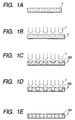
- Figs. 1A to 1E are views which schematically illustrate a method for processing ink discharge ports of an ink jet recording head in accordance with a first embodiment of the present invention.
- the progressive states of process in this method are schematically shown as the time elapses.
- a reference numeral 2 designates a resin plate which is the basic material used for the formation of ink discharge ports. Then, as shown in Fig. 1B, the laser beams 1 that irradiate light are radiated on the resin plate 2 in a configuration of plural discharge ports through the mask having a plurality of opening patters formed at predetermined intervals so that the arrangement density of the discharge ports become 900 dpi.
- the femtosecond laser is used on the following condition: the irradiating laser beams are near infrared rays having the wavelength of 775 nm; the width of radiation pulse time is 150 femtoseconds per pulse; the light energy of the laser radiation is 15 ⁇ J per pulse; and the radiation energy density (fluence) is approximately 1J/cm 2 per pulse.
- each portion at 203 where beams are radiated is ablatively processed and gradually etched.
- Fig. 1E the penetration process is completed for the resin plate 2 by use of the predetermined pattern, and the radiation of laser beams is suspended, thus completing the formation of each of ink discharge ports 201.
- Figs. 2A to 2E are views which schematically illustrate a method for processing ink discharge ports of an ink jet recording head in accordance with the conventional method.
- the progressive states of the conventional process are schematically shown as the time elapses.
- a reference numeral 2 designates a resin plate which is the basic material used for the formation of ink discharge ports.
- the laser beams 1 that irradiate light are radiated on the resin plate 2 in the form of the predetermined pattern in the same manner as shown In the aforesaid embodiment.
- the far ultraviolet rays having the wavelength of 248 nm are used as the irradiating laser beams; the width of radiation pulse time is 15 nanoseconds per pulse; the light energy of the laser radiation is 500 mJ per pulse; and the radiation energy density (fluence) is approximately 1J/cm 2 per pulse.
- each portion at 213 where beams are irradiate is ablatively processed and gradually etched.
- the temporal width of oscillation pulse of the irradiating layer beams is as long as 15 nanoseconds, the light energy absorbed into the resin plate 2 is partly converted into thermal energy, which is caused to spread in the entire body of the resin plate at given conduction rate eventually, thus allowing the resin plate 2 to expand in the directions indicated by arrows in Fig. 2C.
- the etching further advances, and the resin plate 2 is in a state immediately before complete penetration only with a thin skin being left intact as at 212.
- the thermal expansion of the resin plate further advances.
- the nozzles located more on the outer side from the center are directed more outward in the processed state of ink discharge ports 212.
- the amount of accumulated heat of the resin plate increases as the etching process advances.
- resin is fused in each vicinity of the portions where laser beams are irradiate to give curvature to each edge of etching inevitably.
- Fig. 2E the penetration process is completed for the resin plate 2 by use of the predetermined pattern, and the radiation of laser beams is suspended, thus completing the formation of each of ink discharge ports 211.
- the nozzles are directed outward when ink discharge ports are processed, for example. Also, curvature is given to each edge inevitably. The ink discharge ports thus formed make it difficult to discharge ink droplets straightly in parallel.
- the present embodiment presents extremely smooth surface, and that there are almost no flushes observable on the surface.
- This condition contributes to the reduction of factors that may bring about the flow disturbance of unwanted ink on the ink flow passage portion of an ink jet recording head or the disturbance of discharge direction, which should be preferable for performing high quality ink discharges.
- ultraviolet rays as the wavelength of the laser beams radiated here during the pulse radiation time of one picosecond or less. It may be possible to use visible rays or infrared rays without any problem as far as a work piece can absorb the light of such wavelength radiated from either of them. By the application of one from the visible rays to near infrared rays having the wavelength of laser beams of 350 to 1,000 nm in particular, it becomes easier to secure the laser power. Also, a material for general use can be utilized for lenses and components required for the formation of an optical system with lesser possibility of damages given to the optical system, and at the same time, as compared with the use of the conventional ultraviolet laser, the running costs are reduced significantly.
- the processing material is not necessarily limited to resin.
- resin for example, it is possible to process ceramic material, metallic material, or the like.
- metals such as SUS, opaque ceramics, or Si.
- the ablation processing is executable, because the capability of the temporal energy density is high.
- the processing material which is used in general for a structural member of ink discharge ports, ink flow paths, an ink liquid chamber, or an ink supply port of an ink jet recording head, is polyimide, polysulfone, or some other resin material.
- the material is no longer limited thereto, but inorganic material, glass material, metallic material, or semiconductor material is now ablatively processed by the application of laser. As a result, more freedom is now given to the selection of materials for a structural member of ink discharge ports, ink flow paths, an ink liquid chamber, or an ink supply port.
- the present invention makes it possible to process the Si base plate in a desired configuration without any restrictions imposed upon the processed shape when the anisotropic etching is used.
- the ceramic material or the like which has a high fusion point is used for the discharge port plate, it becomes possible to give high temperature treatment, such as water-repellent process, to the surface of the ink discharge ports.
- Fig. 3 is a view which schematically shows the optical system of a laser processing apparatus in accordance with the first embodiment of the present invention.
- the beam flux 1 oscillated from the laser main body (not shown) is induced into the fly eyes or some other optical integrator 10 to decompose the incident laser beam flux into plural numbers, and the decomposed beam fluxes are superposed by use of the field lens 11 on the mask 12 having a plurality of opening patterns formed at predetermined pitches, thus correcting the illuminating intensity of laser substantially equal for illuminating the mask.
- the field lens 11 projects the dot images converged on plural points by use of the fly eye lenses 10 on the positions of aperture 13 of the mask pattern projection lens 14, thus forming the Koehler illumination system.
- the laser beams are illuminated on the mask 12. Then, the mask pattern formed on the mask 12 is projected onto the surface of a work piece, such as an orifice plate 2, by use of the projection focusing lens 14. In this way, the orifice plate 2 is processed by means of the laser oscillation.
- Figs. 4A to 4D and Figs. 5E to 5G are views which illustrate the steps of processing a cantilever to be manufactured by laser processing in accordance with a second embodiment of the present invention.
- a basic member is prepared in such a manner that an aluminum thin film 42 is formed on a silicon base plate 41 by use of vapor deposition or sputtering. Then, a resin film 43 (actually, a resist film) is coated on it by means of spin coating.
- a metallic film 44 (an elastic metal film such as aluminum or copper) is formed by means of vapor deposition.
- the laser in use is near infrared having the wavelength of 775 nm; the temporal width of radiated pulse is 150 femtoseconds per pulse; the light energy of laser radiation is 800 microjouls per pulse; the radiated energy density (fluence) is approximately 50 jouls/cm 2 ; and the pulse energy density is approximately 300 terawatts/cm 2 .
- the resin layer 43 is fused and removed to complete the structure of a cantilever.
- the electric charges are accumulated on the leading end of the cantilever with the electric filed which is formed by drawing wire from the silicon base plate.
- the portion of the cantilever at 44 is open and raised as shown in Fig. 5G. In other words, a microlever is produced, which is open or closed by the switching of electric fields.
- Figs. 6A to 6C are views which illustrate the steps of processing the ink discharge ports to be manufactured by laser processing in accordance with a third embodiment of the present invention.
- an orifice plate member is prepared by inserting a thin copper foil 62 into the polysulfone sheet 61.
- the polysulfone layer 61 and the copper foil layer 62 are processed by sublimating ablution at a time to form the ink discharge ports 40 by irradiating the ultrashort pulse laser having the predetermined pattern by use of the mask projection optical system or the like.
- the laser used in this case is the same as the one used for the second embodiment, which is the near infrared rays having the wavelength of 775 nm; the temporal width of radiated pulse is 150 femtoseconds per pulse; the light energy of laser radiation is 800 microjouls per pulse; the radiated energy density (fluence) is approximately 10 jouls/cm 2 ; and the pulse energy density is approximately 60 terawatts/cm 2 .
- the orifice plate 60 having the ink discharge ports 40 formed therefor is adhesively bonded to the ink jet main body 65 after being aligned with the position of the ink flow paths 71, thus manufacturing the principal part of the ink jet recording head.
- Figs. 7A to 7C are views which illustrate the steps of processing the ink flow paths and an ink liquid chamber to be provided for the ceiling plate of an ink jet recording head in accordance with a fourth embodiment of the present invention.
- a plate member which is a polysulfone plate 61 with glass fillers being mixed in it in order to suppress the thermal expansion coefficient.
- the ultrashort pulse laser is radiated with predetermined pattern by use of the mask projection optical system or the like to process it together with the glass fillers by the sublimating ablation, hence forming the ink flow paths 71 and the ink liquid chamber 72 as shown in Fig. 7C.
- the laser used in this case is the same as the one used for the second and third embodiments, which is the near infrared rays having the wavelength of 775 nm; the temporal width of radiated pulse is 150 femtoseconds per pulse; the light energy of laser radiation is 800 microjouls per pulse; the radiated energy density (fluence) is approximately 10 jouls/cm 2 ; and the pulse energy density is approximately 60 terawatts/cm 2 .
- the silicon IC base plate 80 having the ink discharge pressure generating elements 81 incorporated thereon is adhesively bonded with the ink flow paths 71 and ink discharge pressure generating elements 81 after alignment therewith.
- the orifice plate 60 is adhesively bonded with the ink discharge ports 40 and ink flow paths 71 after alignment therewith to manufacture the principal part of an ink jet recording head.
- Figs. 10A and 10B are views which illustrate the principal part of ink discharge portion for a plane discharge type ink jet recording head in accordance with a fifth embodiment of the present invention.
- Fig. 10A is a view which shows the ink discharge surface of the ink discharge principal portion of a plane discharge type ink jet recording head.
- Fig. 10B is a cross-sectional view taken on the position 10B - 10B in Fig. 10A.
- the ink liquid chamber 1024, the ink flow paths 1023, the ink buffer chamber 1022, and the ink discharge ports 1021 are processed and formed using a method represented in Fig. 9 on a silicon IC base plate 1010 having ink discharge generating elements 1011 installed thereon in a state where a resin plate 1020, which is transparent in the range from visible rays to near infrared rays, is adhesively bonded therewith.
- the ultrashort pulse laser beams one picosecond or less
- having the wavelength of 775 nm is convergently radiated onto the predetermined position inside the resin plate 1020 for the formation of these members described above.
- the details of the laser used here is: near infrared rays having the wavelength of 775 nm; the temporal width of radiated pulse is 150 femtoseconds per pulse; the light energy of laser radiation is set so that the energy density becomes approximately 20 gigawatts/cm 2 in a range of ⁇ 10 ⁇ m by converging the laser beams which have been reduced to 5.0 nanojouls per pulse.
- the resin plate 1020 is bonded onto the silicon IC base plate 1010 having the ink discharge pressure generating elements 1011 installed thereon, the ink liquid chamber 1024, the ink flow paths 1023, the ink buffer chamber 1022, and the ink discharge ports 1021 are process and formed.
- the laser processing is possible with the ink discharge pressure generating elements 1011 and the patterns of the silicon IC base plate 1010 as the criteria for that processing.
- the bonding alignment errors may be eliminated so that the ink liquid chamber 1024, the ink flow paths 1023, the ink buffer chamber 1022, and ink discharge ports 1021 can be incorporated in higher precision.
- Figs. 11A and 11B are views which illustrate the principal part of ink discharge portion for an edge face discharge type ink jet recording head having the ink flow paths processed and formed by the laser processing method in accordance with a sixth embodiment of the present invention.
- Fig. 11A is a plan view of an edge face discharge type ink jet recording head
- Fig. 11B is a sectional view which is indicated by arrows, taken on the position 11B - 11B.
- Figs. 12C and 12D are the sectional views indicated by arrows, taken on the positions 12C - 12C and 12D - 12D in Fig. 11A, respectively.
- the resin plate 1140 having the ink nozzle buffer chamber 1141 and the ink discharge ports 1142 incorporated thereon is bonded and formed on the silicon IC base plate 1130 having ink discharge pressure generating elements 1131 installed thereon.
- the resin plate 1150 is bonded, which is transparent in the range from visible rays to near infrared rays, having thereon the ink liquid chamber 1152 and the ink supply port 1153 incorporated by molding formation or the like.
- the ink flow paths 1151 are processed and formed by use of the method represented in Fig.
- the details of the laser used here is: near infrared rays having the wavelength of 775 nm; the temporal width of radiated pulse is 150 femtoseconds per pulse; the light energy of laser radiation is set so that the energy density becomes approximately 15 gigawatts/cm 2 in a range of ⁇ 10 ⁇ m by converging the laser beams which have been reduced to 3.5 nanojouls per pulse. With this setting, the inner process is executed.
- the ink flow paths 1151 can be drawn around three-dimensionally inside the resin plate 1150. Therefore, in accordance with the present embodiment, the structure is arranged so that ink of three colors, YMC (Yellow, Magenta, and Cyan), are supplied from each of the ink supply ports 1153Y, 1153M, and 1153C, respectively, and then, the ink flow paths of the corresponding colors 1151Y, 1151M, and 1151C are piped through the ink liquid chambers of the corresponding colors 1152Y, 1152M, and 1152C for guiding ink to the ink nozzle buffer 1141 to enable ink of YMC colors to be circulated in that order.
- YMC yellow, Magenta, and Cyan
- the discharge nozzles which are arranged one-dimensionally to circulate ink of YMC colors from the YMC three-color ink liquid chambers, are connected per color, thus making it possible to form an ink jet recording head having discharge cells arranged for adjacent three colors, respectively.
- this ink jet recording head there is no need for making resist adjustments between the respective colors. No color deviations nor color phase changes occur to make it unnecessary to provide a complicated function to correct color resist or to make color resist adjustment between respective colors. Then, images can be printed with stabilized color reproduction.
- an ink jet recording head having discharge cells arranged for adjacent four colors of YMCK (Yellow, Magenta, Cyan, and Black), not necessarily for adjacent three colors of YMC described above, by connecting the discharge nozzles arranged one-dimensionally to circulate YMCK colors from the corresponding ink liquid chambers containing four colors, YMCK, respectively.
- YMCK Yellow, Magenta, Cyan, and Black
- Fig. 13 is a view which illustrates the outline of a processing method in accordance with a seventh embodiment of the present invention.
- a mask 136 is illuminated by the laser beams 131 which are radiated from a laser oscillator (not shown) which radiates the laser beams in the ultrashort pulse radiation time (one picosecond or less). Then, the laser beams that have passed the mask pattern 138 are projected to be focused through a projection lens 137.
- the focusing image is focused on the surface of a material (B) 133 positioned in back of a material (A) 132.
- the material (A) 132 and material (B) 133 are held by a base plate 134 as a work piece.
- the laser beams 131 are carried in the patter of the mask patter 138 to pass the material (A) 132 which is transparent with the light absorbance of approximately 0.1%, while keeping its energy almost as it is at the light wavelength of the laser beams, thus being radiated on the material (B) 133 whose light absorptance is set at 50% or more with the light wavelength of the laser beams.
- the material (B) 133 that receives the laser radiation and absorbs the light energy 50% or more creates the sublimation phenomenon by the absorption of energy that exceeds the threshold value of ablation processing due to the predetermined light energy density of the laser beams. In this manner, a hole 135 is formed inside the work piece.
- Figs. 14A and 14B are views which illustrate the principal part of ink discharges for a plane discharge type ink jet recording head having the ink flow paths processed and formed by the laser processing method in accordance with the seventh embodiment of the present invention.
- Fig. 14A is the view observed from the ink discharge surface side.
- Fig. 14B is a cross-sectional view, taken line 14B - 14B in Fig. 14A.
- the blue polysulfone plate 1430 in which a blue dye is dispersed and mixed with the light absorptance of approximately 60% in the near infrared region of 775 nm which is the wavelength range of the laser beams to be used, is adhesively bonded to the silicon IC base plate 1410 having the ink discharge pressure generating elements 1411 installed thereon.
- the blue polysulfone plate 1430 there is prepared a blank to which is adhesively bonded the colorless polysulfone plate 1420 having the light absorptance of 0.5% or less in the near infrared region of 775 nm which is the wavelength region of the laser beams to be used.
- the laser beams of 775 nm wavelength of the near infrared ultrashort pulse are allowed to pass the colorless polysulfone plate 1420 and irradiate on the predetermined positions of the blue polysulfone plate 1430.
- the ink liquid chamber 1433, the ink flow paths 1432, and the ink buffer chamber 1431 are processed and formed with the method described in conjunction with Fig. 13.
- the details of the laser energy transfer in use are: near infrared rays having the wavelength of 775 nm; the temporal width of radiated pulse is 150 femtoseconds per pulse; the light energy of laser radiation is allowed to pass a mask pattern with the energy density of approximately 50 megawatts/cm 2 by irradiating the laser beams which are reduced to the 400 microjouls per pulse on an area of 20 mm ⁇ 170 mm of the mask 136, and then, the mask pattern image is reduced within an area or approximately 4 mm ⁇ 34 mm through a 1/5 projection of the projection lens.
- the laser is radiated on the work piece with the energy density of approximately one gigawatt/cm 2 due to the energy loss incurred when passing the mask and the optical system.
- the light absorptance of the colorless polysulfone resin is approximately 0.1% with the wavelength of 775 nm.
- the light absorptance of the blue polysulfone resin is approximately 60% with the wavelength of 775 nm.
- the threshold value of ablation processing of polysulfone resin is the energy density of approximately 15 megawatts/cm 2 .
- the threshold value of ablation processing of the colorless polysulfone resin by laser radiation is approximately 15 gigawatts/cm 2
- that of the blue polysulfone resin is approximately 0.025 gigawatts/cm 2
- the laser beams having the energy density of approximately one gigawatt/cm 2 which are radiated on the work piece are allowed to pass the colorless polysulfone plate 1420, but absorbed by the blue polysulfone plate 1430, hence processing the blue polysulfone plate 1430 by the predetermined pattern.
- the ink liquid chamber 1433, the ink flow paths 1432, and the ink buffer chamber 1431 are process and formed.
- the laser processing is performed with the ink discharge pressure generating elements 1411 and the pattern of the silicon IC base plate 1410 as the criteria therefor.
- the ink flow paths 1432, and the ink buffer chamber 1431 have been processed and formed on the blue polysulfone plate 1430, it becomes possible to eliminate the bonding alignment errors so that the ink liquid chamber 1433, the ink flow paths 1432, and the ink buffer chamber 1431 can be incorporated in higher precision.
- the principal part of the ink discharge portion of an ink jet recording head of the fifth to seventh embodiments described above can be processed as an ink jet recording head through the steps given below.
- an electric base plate for which the terminals for use of ink discharge pressure generating elements are pattern is bonded
- an aluminum or alumina ceramics base plate is bonded to the silicon IC base plate for heat radiation use. Then, the holder that holds each of the members and the ink tank used for ink supply are bonded to assemble an ink jet recording head, hence providing a unit that functions as an ink jet recording head.
- Fig. 15 is a view which schematically shows the optical path of the mask pattern projection optical system of a laser processing apparatus in accordance with an eighth embodiment of the present invention.
- the laser oscillator uses laser that oscillates in a pulse radiation time of one picosecond or less. More specifically, the radiated laser beams are near infrared rays of 775 nm wavelength, and the temporal width of radiated pulse is 150 femtoseconds per pulse. The light energy of the laser radiation is 15 ⁇ J per pulse. Also, an orifice plate of polysulfone of 50 ⁇ m thick is used for the main body of an ink jet recording head. Ink discharge ports are formed for this orifice plate.
- the structure is arranged to induce the beam flux 1501 oscillated from the laser main body (not shown) into the fly eyes or some other optical integrator 1510 in order to divide the incident laser beam flux into plural numbers, and then, to superpose the divided beam fluxes by the field lens 1511 on the mask 151 having a plurality of opening patterns formed at predetermined pitches, thus correcting the illuminating intensity of laser substantially equal to illuminate the mask.
- the field lens 1511 projects the dot images converged on plural points by use of the fly eye lenses 1510 on the positions of aperture 1512 of the mask pattern projection lens 1513, thus forming the Koehler illumination system.
- the laser beams are illuminated on the mask 151. Then, the mask pattern formed on the mask 151 is projected and focused on the surface of the orifice plate 152 of the ink jet recording head 153, which is a work piece, by use of the projection focusing lens 1513. In this way, the ink discharge ports are processed by means of the laser oscillation.
- the ink discharge ports are processed by the laser processing apparatus described above as a work piece. Now, the details thereof will be described in conjunction with Fig. 16.
- a work piece, polysulfone resin is at first mixed with blue dye using the radiation of laser beams, which is near infrared rays of 775 nm wavelength with a light source having the temporal width of oscillating radiation of 150 femtoseconds per pulse, thus coloring the polysulfone resin entirely in blue up to the interior thereof.
- the orifice plate which is formed by the aforesaid polysulfone in a thickness of 50 ⁇ m, is used as the main body of an ink jet recording head. Then, the ink discharge nozzles are formed on the orifice plate by use of the aforesaid optical system.
- the ink discharge ports are formed by the radiation of laser of approximately 2000 pulses for an orifice plate formed by the orifice plate of original color, that is, transparent and colorless
- the ink discharge ports can be formed by the radiation of laser of approximately 100 pulses when the polysulfone colored in blue is used for the orifice plate as described above. Therefore, it becomes possible to obtain the processing efficiency almost as much as 20 times.
- a reference numeral 33 designates a base plate.
- the ink discharge pressure elements 34 such as electrothermal transducing elements, electromechanical transducing elements, are arranged for discharge ink.
- Each of the ink discharge pressure generating elements 34 is arranged in each of the ink flow paths 31 communicated with the discharge ports 201.
- Each of the ink flow paths 31 is communicated with the common liquid chamber 32.
- an ink supply tube (not shown) is connected to supply ink from an ink tank through the ink supply tube.
- a reference numeral 35 designates a ceiling plate having the recessed portion to form the ink flow paths 31 and the common liquid chamber 32, which is bonded to the base plate 33 to form the ink flow paths 31 and the common liquid chamber 32.
- the discharge port plate 2 (hereinafter referred to an orifice plate) is arranged with discharge ports 201.
- An ink jet recording head of the kind can be manufactured as given below.
- the heaters 34 which are heat generating resistive elements for use of ink discharge pressure generating, the integrated circuit, such as shift registers, (not shown), and the electric wiring are patterned on the silicon base plate to form the base plate 33, and at the same time, the ceiling plate 35 is produced by a silicon plate where the recessed portion that becomes the ink flow paths 31 and the ink liquid chamber 32, and an ink supply port (not shown) are formed by means of the chemical etching.
- the base plate 33 and the ceiling plate 35 are aligned so that the edge face on the ink discharge side and the arrangement of the ink flow paths 31 and heaters 34 are in agreement, and then, bonded together.
- the orifice plate 2 is aligned with and bonded to the bonded body of the ceiling plate 35 and the base plate 33 so that the nozzles (discharge ports) 201 are set on the predetermined position on the edge face on the ink discharge side thereof.
- the terminals for use of heater driving (not shown) are patterned and bonded to the electric base plate, and at the same time, the base plate formed by aluminum, ceramics, or the like is bonded to the base plate 33. Then, the holder that holds each of the members, and the ink tank for supply ink are connected to assemble an ink jet recording head.
- an orifice plate formed by polysulfone of 50 pm thick is used for the main body of an ink jet recording head. Then, using the aforesaid optical system ink discharge ports are formed for the orifice plate with the radiation of laser beams which are near infrared rays of 775 nm wavelength having the temporal width of radiation pulse being 150 femtoseconds/cm 2 per pulse; the light energy of laser radiation being 15 ⁇ J per pulse; and the radiated energy density (fluence) being approximately 1J/cm 2 per pulse.
- 50 ink jet recording heads are manufactured to observe the shape of discharge ports, with the result that all the discharge ports present clean and smooth edges with the formation of ink discharge ports arranged in parallel in high precision, and that the variation of the aperture diameter of each discharge port on the edge portion on the ink discharging side is significantly reduced as compared with the conventional one.
- the actual printing is performed by use of the ink jet recording heads thus manufactured, with the result that evenly lined print dots are recorded with clear and smooth shape of dots, thus obtaining images of excellent print quality.
- an ink jet recording head is described.
- the present invention is not necessarily limited thereto.
- the invention is preferably applicable to the laser processing related to the micromachining of a semiconductor base plate or the like. Therefore, it is to be understood that these are included in the present invention.
- a work piece such as resin, can be processed by ablation with an extremely small amount of light energy.
- the process material is not necessarily limited to resin. Because the processing step is completed before heat dispersion advances from beam radiation even when a material having a higher heat transfer coefficient, such as metal, is processed. As a result, the ablation processing can be effectuated without conditioning any liquid phase.
- the degree of material selection freedom becomes higher when considering the structural members for an ink jet recording head.
- a material having a small linear expansion coefficient can be used. Therefore, it becomes possible to prevent the deviation from taking place on the contact surface of each member due to shearing force.
- ink jet recording head having excellent durability and storage capability which is not easily corroded even by ink having strong alkaline property.
- semiconductor material a structural member can be formed directly on an integrated circuit. Then, if a high fusion point material, such as ceramics, is used for the discharge port plate, it becomes possible to give a higher heat treatment, such as a water-repellent process of the surface of ink discharge ports, among some others.
- the different materials of two kinds or more can be processed by sublimation almost simultaneously in one and the same process. Further, even if the difference of the linear expansion coefficient is large between different materials of two kinds or more, it is possible for the present invention to suppress peeling off between those different materials due to the stress caused by the thermal expansion thereof, because it is made difficult to transfer heat by the present invention during the operation of the ablation processing as compared with the conventional one. As a result, when a precise structure should be formed on a work piece formed by plural kinds of materials, it is possible to implement the laser processing method with simply processing steps or a method for manufacturing an ink jet recording head using such laser processing method, and to provide an ink jet recording head manufactured by such method of manufacture.
- the ultraviolet rays are not necessarily needed for use of the light wavelength of radiated laser by the pulse oscillating time of one picosecond or less. If only the wavelength can be absorbed by a work piece, visible rays or infrared rays can be used.
- the temporal energy density is extremely high so that material can be sublimated for a short period of processing, and that the ablation processing is effectuated without conditioning the liquid phase.
- an ink jet recording head structured by the laser processing method it becomes possible to perform the ablation processing almost simultaneously in one processing step using the aforesaid laser processing method even for the structural member of the recording head formed by inorganic material, glass material, metallic material, semiconductor material, or the arbitrary combination of these materials, not necessarily limited to the resin material, such as polyimide, polysulfone, which is conventionally used for the structural member of the ink discharge ports, the ink flow paths, the ink liquid chamber, or the ink supply port of an ink jet recording head in general. Therefore, it becomes possible to provide more freedom of complex selection of material for the structural member of the ink discharge ports, the ink flow paths, the ink liquid chamber or ink supply port.
- the resin material such as polyimide, polysulfone
- the process of sublimating process begins with the region where it exceeds the threshold value of ablation processing of the work piece by converging light more than the predetermined energy density inside the work piece which is transparent in terms of the light wavelength of laser beams as described earlier.
- a method for manufacturing an ink jet recording head using the aforesaid layer processing method it becomes possible not only to suppress the alignment errors caused by assembling structural members of the ink jet recording head, as well as the degradation of the ink discharge characteristics caused by the bonding deformation, but also, to draw around ink flow paths three-dimensionally inside a resin work piece, such as polysulfone or polyimide.
- a resin work piece such as polysulfone or polyimide.
- the YMC yellow, magenta, and cyan
- the enhancement of processing efficiency can be attempted by forming a work piece to be able to absorb laser radiation energy.
Landscapes
- Engineering & Computer Science (AREA)
- Physics & Mathematics (AREA)
- Optics & Photonics (AREA)
- Manufacturing & Machinery (AREA)
- Plasma & Fusion (AREA)
- Mechanical Engineering (AREA)
- Laser Beam Processing (AREA)
- Particle Formation And Scattering Control In Inkjet Printers (AREA)
Applications Claiming Priority (10)
| Application Number | Priority Date | Filing Date | Title |
|---|---|---|---|
| JP18469699 | 1999-06-30 | ||
| JP18459099 | 1999-06-30 | ||
| JP18469699 | 1999-06-30 | ||
| JP18459099 | 1999-06-30 | ||
| JP31676099 | 1999-11-08 | ||
| JP31681899 | 1999-11-08 | ||
| JP31681899 | 1999-11-08 | ||
| JP31685099 | 1999-11-08 | ||
| JP31685099 | 1999-11-08 | ||
| JP31676099 | 1999-11-08 |
Publications (2)
| Publication Number | Publication Date |
|---|---|
| EP1065023A2 true EP1065023A2 (de) | 2001-01-03 |
| EP1065023A3 EP1065023A3 (de) | 2003-09-10 |
Family
ID=27528872
Family Applications (1)
| Application Number | Title | Priority Date | Filing Date |
|---|---|---|---|
| EP00113699A Withdrawn EP1065023A3 (de) | 1999-06-30 | 2000-06-28 | Laserbearbeitungsverfahren, Verfahren zur Herstellung eines Tintenstrahlaufzeichnungskopfes mittels eines solchen Herstllungsverfahren, und mittels eines solchen Herstellungserfahrens hergestellter Tintenstrahlaufzeichnungskopf |
Country Status (10)
| Country | Link |
|---|---|
| US (1) | US6693656B1 (de) |
| EP (1) | EP1065023A3 (de) |
| KR (1) | KR100340896B1 (de) |
| CN (1) | CN1158162C (de) |
| AU (1) | AU4373500A (de) |
| BR (1) | BR0002930A (de) |
| CA (1) | CA2313204A1 (de) |
| MX (1) | MXPA00006539A (de) |
| SG (1) | SG90732A1 (de) |
| TW (1) | TW513348B (de) |
Cited By (2)
| Publication number | Priority date | Publication date | Assignee | Title |
|---|---|---|---|---|
| WO2003099569A2 (en) * | 2002-05-23 | 2003-12-04 | Matsushita Electric Industrial Co., Ltd. | Laser processing method using ultra-short pulse laser beam |
| US6685301B2 (en) | 2001-02-08 | 2004-02-03 | Canon Kabushiki Kaisha | Liquid repellent member, method for manufacturing liquid repellent member, ink jet head using liquid repellent member, method for manufacturing ink jet head and method for supplying ink |
Families Citing this family (15)
| Publication number | Priority date | Publication date | Assignee | Title |
|---|---|---|---|---|
| EP1859071A4 (de) * | 2005-02-23 | 2010-04-14 | Picodeon Ltd Oy | Abscheidungsverfahren mit gepulstem laser |
| US7977602B2 (en) * | 2007-03-21 | 2011-07-12 | Photon Dynamics, Inc. | Laser ablation using multiple wavelengths |
| JP5208092B2 (ja) * | 2009-11-18 | 2013-06-12 | キヤノン株式会社 | 液体供給部材の製造方法及び液体吐出ヘッドの製造方法 |
| EP3010723B1 (de) * | 2013-06-18 | 2021-09-22 | Apple Inc. | Lasergravierte reflektierende oberflächenstrukturen und verfahren dafür |
| KR20160005802A (ko) | 2014-07-03 | 2016-01-18 | 마이크로 인스펙션 주식회사 | 레이저 가공장치 |
| US20160184926A1 (en) * | 2014-12-30 | 2016-06-30 | Suss Microtec Photonic Systems Inc. | Laser ablation system including variable energy beam to minimize etch-stop material damage |
| US10569365B2 (en) * | 2015-11-23 | 2020-02-25 | The Boeing Company | Method for preparing a fluid flow surface |
| US20170176856A1 (en) | 2015-12-21 | 2017-06-22 | Az Electronic Materials (Luxembourg) S.A.R.L. | Negative-working photoresist compositions for laser ablation and use thereof |
| DE102017112086A1 (de) * | 2017-06-01 | 2018-12-06 | Carl Zeiss Meditec Ag | Künstliche Augenlinse mit diffraktiver Gitterstruktur sowie Verfahren zum Herstellen einer künstlichen Augenlinse |
| DE102017112087A1 (de) | 2017-06-01 | 2018-12-06 | Carl Zeiss Meditec Ag | Künstliche Augenlinse mit lasererzeugter doppelbrechender Struktur sowie Verfahren zum Herstellen einer künstlichen Augenlinse |
| DE102017112085A1 (de) | 2017-06-01 | 2018-12-06 | Carl Zeiss Meditec Ag | Künstliche Augenlinse mit darin ausgebildetem Medikamentendepot und Verfahren zum Herstellen einer künstlichen Augenlinse |
| US11201077B2 (en) * | 2017-06-12 | 2021-12-14 | Kulicke & Soffa Netherlands B.V. | Parallel assembly of discrete components onto a substrate |
| KR102445450B1 (ko) | 2017-06-12 | 2022-09-20 | 쿨리케 & 소파 네덜란드 비.브이. | 개별 부품들의 기판 상으로의 병렬적 조립 |
| JP2019107789A (ja) * | 2017-12-15 | 2019-07-04 | 株式会社小糸製作所 | 樹脂成形品および車両用部品 |
| CN113399829B (zh) * | 2021-07-09 | 2022-11-11 | 东莞市中麒光电技术有限公司 | 焊接装置及使用该焊接装置的焊接方法 |
Citations (2)
| Publication number | Priority date | Publication date | Assignee | Title |
|---|---|---|---|---|
| JPH02121842A (ja) | 1988-10-31 | 1990-05-09 | Canon Inc | インクジェット記録ヘッドおよびインクジェット記録ヘッドの製造方法 |
| JPH02121845A (ja) | 1988-10-31 | 1990-05-09 | Canon Inc | インクジェット記録ヘッドの製造方法 |
Family Cites Families (14)
| Publication number | Priority date | Publication date | Assignee | Title |
|---|---|---|---|---|
| JPS57102016A (en) * | 1980-12-17 | 1982-06-24 | Hitachi Ltd | Pattern generator |
| GB8722085D0 (en) | 1987-09-19 | 1987-10-28 | Cambridge Consultants | Ink jet nozzle manufacture |
| US5208604A (en) | 1988-10-31 | 1993-05-04 | Canon Kabushiki Kaisha | Ink jet head and manufacturing method thereof, and ink jet apparatus with ink jet head |
| US5312396A (en) * | 1990-09-06 | 1994-05-17 | Massachusetts Institute Of Technology | Pulsed laser system for the surgical removal of tissue |
| ATE144197T1 (de) * | 1991-02-20 | 1996-11-15 | Canon Kk | Tintenstrahlaufzeichnungskopf, tintenstrahlaufzeichnungsvorrichtung diesen verwendend und verfahren zu seiner herstellung |
| DE59103714D1 (de) * | 1991-10-07 | 1995-01-12 | Siemens Ag | Laserbearbeitungsverfahren für einen Dünnschichtaufbau. |
| EP0542656A1 (de) * | 1991-10-31 | 1993-05-19 | International Business Machines Corporation | Musterübertragung durch überdeckende Beleuchtung von gemusterten Wärmeleitern und gemusterten Wärmeisolatoren auf einen thermischen Leiter |
| US5349155A (en) * | 1992-01-17 | 1994-09-20 | Fujitsu Limited | Insulating material for wiring substrate and method of producing multi-layered wiring substrate |
| US5656186A (en) * | 1994-04-08 | 1997-08-12 | The Regents Of The University Of Michigan | Method for controlling configuration of laser induced breakdown and ablation |
| US5786560A (en) * | 1995-03-31 | 1998-07-28 | Panasonic Technologies, Inc. | 3-dimensional micromachining with femtosecond laser pulses |
| US5720894A (en) * | 1996-01-11 | 1998-02-24 | The Regents Of The University Of California | Ultrashort pulse high repetition rate laser system for biological tissue processing |
| JP3501598B2 (ja) * | 1996-10-16 | 2004-03-02 | キヤノン株式会社 | レーザー加工方法、インクジェット記録ヘッド及びインクジェット記録ヘッド製造装置 |
| US6156030A (en) * | 1997-06-04 | 2000-12-05 | Y-Beam Technologies, Inc. | Method and apparatus for high precision variable rate material removal and modification |
| DE19736110C2 (de) | 1997-08-21 | 2001-03-01 | Hannover Laser Zentrum | Verfahren und Vorrichtung zur grat- und schmelzfreien Mikrobearbeitung von Werkstücken |
-
2000
- 2000-06-28 SG SG200003712A patent/SG90732A1/en unknown
- 2000-06-28 US US09/604,913 patent/US6693656B1/en not_active Expired - Fee Related
- 2000-06-28 EP EP00113699A patent/EP1065023A3/de not_active Withdrawn
- 2000-06-29 TW TW089112898A patent/TW513348B/zh not_active IP Right Cessation
- 2000-06-29 CA CA002313204A patent/CA2313204A1/en not_active Abandoned
- 2000-06-29 AU AU43735/00A patent/AU4373500A/en not_active Abandoned
- 2000-06-30 KR KR1020000036818A patent/KR100340896B1/ko not_active IP Right Cessation
- 2000-06-30 MX MXPA00006539A patent/MXPA00006539A/es unknown
- 2000-06-30 CN CNB00124244XA patent/CN1158162C/zh not_active Expired - Fee Related
- 2000-06-30 BR BR0002930-0A patent/BR0002930A/pt not_active IP Right Cessation
Patent Citations (2)
| Publication number | Priority date | Publication date | Assignee | Title |
|---|---|---|---|---|
| JPH02121842A (ja) | 1988-10-31 | 1990-05-09 | Canon Inc | インクジェット記録ヘッドおよびインクジェット記録ヘッドの製造方法 |
| JPH02121845A (ja) | 1988-10-31 | 1990-05-09 | Canon Inc | インクジェット記録ヘッドの製造方法 |
Cited By (4)
| Publication number | Priority date | Publication date | Assignee | Title |
|---|---|---|---|---|
| US6685301B2 (en) | 2001-02-08 | 2004-02-03 | Canon Kabushiki Kaisha | Liquid repellent member, method for manufacturing liquid repellent member, ink jet head using liquid repellent member, method for manufacturing ink jet head and method for supplying ink |
| US7074314B2 (en) | 2001-02-08 | 2006-07-11 | Canon Kabushiki Kaisha | Liquid repellent member, method for manufacturing liquid repellent member, ink jet head using liquid repellent member, method for manufacturing ink jet head and method for supplying ink |
| WO2003099569A2 (en) * | 2002-05-23 | 2003-12-04 | Matsushita Electric Industrial Co., Ltd. | Laser processing method using ultra-short pulse laser beam |
| WO2003099569A3 (en) * | 2002-05-23 | 2004-07-08 | Matsushita Electric Ind Co Ltd | Laser processing method using ultra-short pulse laser beam |
Also Published As
| Publication number | Publication date |
|---|---|
| TW513348B (en) | 2002-12-11 |
| CN1158162C (zh) | 2004-07-21 |
| US6693656B1 (en) | 2004-02-17 |
| CN1287899A (zh) | 2001-03-21 |
| MXPA00006539A (es) | 2003-10-24 |
| SG90732A1 (en) | 2002-08-20 |
| EP1065023A3 (de) | 2003-09-10 |
| KR100340896B1 (ko) | 2002-06-20 |
| CA2313204A1 (en) | 2000-12-30 |
| BR0002930A (pt) | 2001-01-30 |
| AU4373500A (en) | 2001-01-04 |
| KR20010007596A (ko) | 2001-01-26 |
Similar Documents
| Publication | Publication Date | Title |
|---|---|---|
| US6693656B1 (en) | Laser processing method, method for manufacturing ink jet recording head using such method of manufacture, and ink jet recording head manufactured by such method of manufacture | |
| US5408738A (en) | Method of making a nozzle member including ink flow channels | |
| US5442384A (en) | Integrated nozzle member and tab circuit for inkjet printhead | |
| EP0624471B1 (de) | Maskenmuster für die Herstellung von konische Tintenstrahldüsen | |
| US5305015A (en) | Laser ablated nozzle member for inkjet printhead | |
| KR100388182B1 (ko) | 레이저 가공 방법, 그 방법을 이용한 잉크 제트 기록 헤드제조 방법 및 그 방법에 의해 제조된 잉크 제트 기록 헤드 | |
| US20060032841A1 (en) | Forming features in printhead components | |
| JPH0679486A (ja) | インクジェットヘッドの加工方法 | |
| KR100340271B1 (ko) | 레이저 가공 방법, 그 방법을 이용하는 잉크 제트 기록헤드의 제조 방법, 및 그 방법에 의해 제조된 잉크 제트기록 헤드 | |
| JP2001198684A (ja) | レーザ加工方法、該レーザ加工方法を用いたインクジェット記録ヘッドの製造方法、該製造方法で製造されたインクジェット記録ヘッド | |
| US6938341B2 (en) | Method for manufacturing an ink discharge port of an ink jet recording head | |
| US7302309B2 (en) | Laser micromachining methods and systems | |
| KR100374274B1 (ko) | 잉크 제트 기록 헤드 제조 방법, 이러한 방법에 의해제조된 잉크 제트 기록 헤드 및 레이저 가공 방법 | |
| JPH10278279A (ja) | プリントヘッドの製造方法 | |
| JP2001219282A (ja) | レーザ加工方法、該レーザ加工方法を用いたインクジェット記録ヘッドの製造方法、該製造方法で製造されたインクジェット記録ヘッド | |
| CA2084554C (en) | Integrated nozzle member and tab circuit for inkjet printhead | |
| JP5059056B2 (ja) | 微細構造体の製造方法及び液体吐出ヘッドの製造方法 | |
| JP2009233955A (ja) | 微細構造体の製造方法及び液体吐出ヘッドの製造方法 | |
| JP3041551B2 (ja) | 感光性ガラスの加工方法 | |
| JPH11188882A (ja) | 液体噴射記録ヘッドおよびその製造方法 | |
| JP2001010062A (ja) | 液体噴射記録ヘッドの吐出ノズル加工方法および液体噴射記録ヘッドの製造方法 | |
| JPH05124196A (ja) | インクジエツト記録ヘツドの製造方法 | |
| JPH10175299A (ja) | インクジェット記録装置 |
Legal Events
| Date | Code | Title | Description |
|---|---|---|---|
| PUAI | Public reference made under article 153(3) epc to a published international application that has entered the european phase |
Free format text: ORIGINAL CODE: 0009012 |
|
| AK | Designated contracting states |
Kind code of ref document: A2 Designated state(s): AT BE CH CY DE DK ES FI FR GB GR IE IT LI LU MC NL PT SE |
|
| AX | Request for extension of the european patent |
Free format text: AL;LT;LV;MK;RO;SI |
|
| RIC1 | Information provided on ipc code assigned before grant |
Ipc: 7B 23K 26/06 B Ipc: 7B 41J 2/05 B Ipc: 7B 41J 2/16 B Ipc: 7B 23K 26/00 A |
|
| PUAL | Search report despatched |
Free format text: ORIGINAL CODE: 0009013 |
|
| RIC1 | Information provided on ipc code assigned before grant |
Ipc: 7B 23K 26/38 B Ipc: 7B 23K 26/40 B Ipc: 7B 23K 26/06 B Ipc: 7B 41J 2/05 B Ipc: 7B 41J 2/16 B Ipc: 7B 23K 26/00 A |
|
| AK | Designated contracting states |
Kind code of ref document: A3 Designated state(s): AT BE CH CY DE DK ES FI FR GB GR IE IT LI LU MC NL PT SE |
|
| AX | Request for extension of the european patent |
Extension state: AL LT LV MK RO SI |
|
| 17P | Request for examination filed |
Effective date: 20040123 |
|
| D17P | Request for examination filed (deleted) | ||
| 17Q | First examination report despatched |
Effective date: 20040322 |
|
| AKX | Designation fees paid | ||
| REG | Reference to a national code |
Ref country code: DE Ref legal event code: 8566 |
|
| STAA | Information on the status of an ep patent application or granted ep patent |
Free format text: STATUS: THE APPLICATION IS DEEMED TO BE WITHDRAWN |
|
| 18D | Application deemed to be withdrawn |
Effective date: 20040311 |
|
| REG | Reference to a national code |
Ref country code: HK Ref legal event code: WD Ref document number: 1038714 Country of ref document: HK |