EP1063337A2 - Method and device for the continuous heat treatment of a textile fabric, particularly for fixing of dyestuffs - Google Patents
Method and device for the continuous heat treatment of a textile fabric, particularly for fixing of dyestuffs Download PDFInfo
- Publication number
- EP1063337A2 EP1063337A2 EP00110489A EP00110489A EP1063337A2 EP 1063337 A2 EP1063337 A2 EP 1063337A2 EP 00110489 A EP00110489 A EP 00110489A EP 00110489 A EP00110489 A EP 00110489A EP 1063337 A2 EP1063337 A2 EP 1063337A2
- Authority
- EP
- European Patent Office
- Prior art keywords
- web
- treatment
- roller
- superheated steam
- housing
- Prior art date
- Legal status (The legal status is an assumption and is not a legal conclusion. Google has not performed a legal analysis and makes no representation as to the accuracy of the status listed.)
- Granted
Links
Images

Classifications
-
- D—TEXTILES; PAPER
- D06—TREATMENT OF TEXTILES OR THE LIKE; LAUNDERING; FLEXIBLE MATERIALS NOT OTHERWISE PROVIDED FOR
- D06B—TREATING TEXTILE MATERIALS USING LIQUIDS, GASES OR VAPOURS
- D06B23/00—Component parts, details, or accessories of apparatus or machines, specially adapted for the treating of textile materials, not restricted to a particular kind of apparatus, provided for in groups D06B1/00 - D06B21/00
- D06B23/04—Carriers or supports for textile materials to be treated
-
- D—TEXTILES; PAPER
- D06—TREATMENT OF TEXTILES OR THE LIKE; LAUNDERING; FLEXIBLE MATERIALS NOT OTHERWISE PROVIDED FOR
- D06B—TREATING TEXTILE MATERIALS USING LIQUIDS, GASES OR VAPOURS
- D06B19/00—Treatment of textile materials by liquids, gases or vapours, not provided for in groups D06B1/00 - D06B17/00
- D06B19/0005—Fixing of chemicals, e.g. dyestuffs, on textile materials
- D06B19/0029—Fixing of chemicals, e.g. dyestuffs, on textile materials by steam
- D06B19/0035—Fixing of chemicals, e.g. dyestuffs, on textile materials by steam the textile material passing through a chamber
-
- D—TEXTILES; PAPER
- D06—TREATMENT OF TEXTILES OR THE LIKE; LAUNDERING; FLEXIBLE MATERIALS NOT OTHERWISE PROVIDED FOR
- D06B—TREATING TEXTILE MATERIALS USING LIQUIDS, GASES OR VAPOURS
- D06B23/00—Component parts, details, or accessories of apparatus or machines, specially adapted for the treating of textile materials, not restricted to a particular kind of apparatus, provided for in groups D06B1/00 - D06B21/00
- D06B23/14—Containers, e.g. vats
- D06B23/16—Containers, e.g. vats with means for introducing or removing textile materials without modifying container pressure
Definitions
- the invention relates to a method for the continuous heat treatment of a textile Goods web, in particular for color fixing, according to the preamble of claim 1 and one corresponding device according to the preamble of claim 8.
- the fixation can be done by lingering on the web of paint Room temperature or the damp or dried web at higher temperatures respectively.
- the fixing treatment depends on the material of the material web and the one applied Dye dependent.
- DE-A 16 35 140 describes a process for the continuous color fixation of man-made fibers in webs by high temperature treatment with convective heat transfer, for example on nozzle-ventilated fixation frames. To even out the Fixing effect is first a rapid heating and then a dwell treatment carried out. During rapid heating, the web is stretched in tension chains and guided over normal guide rollers during the dwell treatment.
- WO 97/14 839 describes a generic method and a device for Color fixation during reactive dyeing of cellulose ware, with which an optimal color yield without aggressive amounts of aids can be achieved.
- liquor is applied to the Goods brought, which is then led into a chamber of an air dryer.
- This Chamber will maintain a steam content of the order of 25% by volume of the air and ensured that the goods were still ready for reaction at the exit of the chamber Has residual moisture.
- Two control loops are used, one for the steam content and one for the residual moisture of the web is used, i.e. there are complex measuring and Control devices required. Due to the length of stay, this fixing procedure is required of the order of 2 minutes in a continuous process with one Web speed of e.g. 40m / min, a content of goods in the dwelling unit, here one Hotflue, of at least 80 m. It is therefore for smaller amounts to be colored (smaller amounts) not economical to use.
- the object of the invention is to provide a process for continuous heat treatment, in particular for color fixing, in which the treatment gas contains superheated steam, according to the Preamble of claim 1, which can be used economically for smaller yields, and one to develop corresponding device according to the preamble of claim 8.
- the heat treatment should be carried out more effectively and therefore faster.
- a method according to the invention for the continuous heat treatment of a textile Material web is the wet web of paint loaded with ink by at least one Treatment chamber transported and in the treatment chambers with a treatment gas, which consists essentially of superheated steam. It is in Treatment gas a steam content of at least 80 vol .-%, preferably of 95 to 100 vol%, i.e. almost pure superheated steam, set.
- the temperature of the superheated steam is 105 to 230 ° C.
- the superheated steam is added in the form of superheated steam about atmospheric pressure used.
- the high vapor content of the treatment gas accelerates due to the Condensability of the superheated steam the heating time, which leads to a further reduction the required dwell time.
- the treatment method according to the invention leads despite the high Steam content and the high product temperature, and thus the increased drying good fixation results, i.e. to a good color yield and a good color quality that the State of the art results.
- the input moisture of the web loaded with the dye liquor when dyeing is native fibers with reactive dye 40 to 80%.
- urea can be dispensed with for most reactive dyes.
- the temperature of the superheated steam can preferably be 160 to 230 ° C according to claim 2 be.
- the dwell time of the web in the device can be according to claim 3 5 to 60 seconds, preferably 10 to 30 seconds. This is enough time complete fixation with good color yield and allows a device smaller Size.
- the process according to the invention is optimal Fixing results also with a residual moisture of the web less than or equal to Equilibrium moisture under normal conditions according to claim 4, i.e. at about 10% Moisture based on the weight of the web of cellulose and about 8% moisture in cotton. This is through the already mentioned accelerating effect of drying for color fixing explained. A regulation of Residual moisture in the web in the device is not necessary.
- the material web could be guided through a steam-filled one Chamber in the form of hanging loops and a meandering guidance of the web around two rows of guide and conveyor rollers belong, insofar as they are used to transport a moist, colored and unfixed web is suitable.
- the web according to claim 5 with the air circulation process guided superheated steam are brought into contact via nozzles directed onto the web. This is possible without color gradients in the method according to the invention, because of the high steam content and possibly the high steam temperature a quick drying of the Material web and thus the dye takes place.
- a further improvement in heat transfer can be achieved if the web is transported according to claim 6 substantially flat through the treatment chamber and above and possibly below the product line arranged nozzle boxes with superheated steam in Is brought into contact.
- nozzle-ventilated fixing clamping frames are used Rapid heating when fixing the color of chemical fibers, i.e. thermosolating, from DE-A 16 35 140 known.
- Devices of this type which are suitable as a treatment gas for hot steam, are in DE 35 11 950, namely a floating dryer and a stenter dryer.
- Tenter frame dryer is known from DE 195 A 46 344. Inlet slot and outlet slot this dryer are installed in the bottom of its housing. The web will be up to on the infeed area and the outfeed area, horizontally, through the dryer guided.
- the material web is preferably used in the method according to the invention by means of a roller conveyor arranged at a distance from a front wall of the housing under a longitudinal tension, in particular from 10 to 100 N / m, through the Treatment chambers transported.
- the distance to the front wall is at least 20%, preferably at least 30%, the length of the horizontal transport path of the web through the treatment chambers.
- the web is only through the roller conveyor performed when it and thus the dye has already dried. While drying and also during the entire fixing process, the web is through Longitudinal tension smoothed out, which is an even fixation and thus an even Color yield guaranteed.
- a guide of the material web through a roller conveyor is above it a simple transport procedure, e.g. compared to a tension chain guide, enables easier entrances and exits to the treatment chamber.
- a device for the continuous heat treatment of a textile web according to Claim 8, in particular for color fixing, according to one of claims 1 to 7, with a vapor-tight housing, with at least one treatment chamber with a circulating air device, i.e. a device for guiding hot steam in a forced air process, with a Recirculation fan and nozzle boxes arranged above and below the web each treatment chamber, with a transport device for essentially flat guidance the web through the housing has according to claim 8 as an essential part of Transport device at least one at a distance from a front wall of the housing arranged roller gear on. The distance to the front wall is at least 20%, preferably at least 30%, the length of the horizontal transport path of the web through the treatment chambers.
- a roller train can have two rollers offset from one another, one relative to the another, adjustable to generate a longitudinal tension.
- a roller mill can also have two bars that guide the web in its transport plane or rollers and one between the two bars or rollers above or below the Transport roller arranged, adjustable vertically to the transport roller exhibit.
- the web is in the form of a loop around the draw roller led around and by deflecting the pull roller perpendicular to the transport plane and the Longitudinal tension maintained.
- a device according to claim 8 is particularly suitable for implementation a method according to claim 7 suitable.
- the roller mill according to claim 9 each in the area in which the abut both treatment chambers, arranged, d. H. the distance to Front wall is about 50% of the length of the horizontal transport path of the web through the treatment chambers.
- the treatment chambers are also fields and the Areas between the treatment chambers called field surges.
- the roller train has two guide rollers and one vertically adjustable Pull roller on, the guide rollers close behind each other and the pull roller in the middle below the guide rollers are arranged.
- This arrangement of the guide rolls and draw rolls enables a narrow butt area of the treatment chamber, i.e. the area or areas in where no nozzle boxes are arranged can be kept small.
- a pull roller which is also designed as an alignment roller according to claim 11, spared additional means for aligning the web.
- the device according to the invention in front of and behind the housing one lock each.
- the locks extend from the floor to over the Transport level of the web and point near the ground and at the level of the transport level Deflection rollers on.
- the locks are divided into a lower, downward-facing antechamber and one further main chamber arranged above.
- Suction channels can be attached to the antechambers or suction boxes are connected.
- Inlet and outlet slots with suction boxes are provided by the separate locks
- Antechamber and suction devices prevent the ingress of air and thus condensation of Prevents steam to water more safely.
- a lock known from DE 198 58 839, in the before the inlet slot of the housing steam is blown onto the web, is to Fixing dye less suitable due to the risk of color gradients.
- Figure 1 shows a system for dyeing with an inventive device for Color fixation.
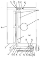
- Figure 2 is an entrance lock, a first treatment chamber and a Rolling device shown.
- a system for dyeing a textile web 1, e.g. made of cotton or cellulose Reactive dye, has a goods store 2 arranged one behind the other in the transport direction, a feed device 3, a coloring device 4, an air passage 5, a device for Color fixation 6, a further feed device 7 and a further goods store 8.
- the front goods store 2 as a container
- the dyeing device 4 as Foulard
- the rear goods store 8 as a winding roller
- the feed devices 3, 7 as Gallows trained.
- the device for color fixing 6 has an entrance lock 9, vapor-tight, heat-insulated housing 10 and an exit lock 11.
- the housing 10 comprises at least one, preferably two to five, here two, modular treatment chambers 12, 13 are lined up through the treatment chambers 12, 13 divided the interior of the housing 10 into two fields arranged one behind the other.
- the Housing 10 is not subdivided and includes all treatment chambers 12, 13.
- each of the treatment chambers 12, 13 there is a circulating air device, i.e. a device for Conduction of superheated steam in a cycle, also called recirculation, with one Recirculation fan 14, a heating device (not shown in FIG. 2) and with nozzle boxes 15 arranged with nozzle openings aimed at the web 1.
- a circulating air device i.e. a device for Conduction of superheated steam in a cycle, also called recirculation
- a heating device not shown in FIG. 2
- nozzle boxes 15 arranged with nozzle openings aimed at the web 1.
- 13 can be several, e.g. two each above and below the web 1 transversely Nozzle boxes 15 extending over the web 1 can be arranged.
- the nozzle openings are preferably designed as slots.
- a transport device has guide rollers 16, 17 in the entrance lock 9 and guide rollers 18, 19, 20 in and behind the exit lock 11 in the area, in which the two treatment chambers 12, 13 abut one another with two rollers Guide rollers 21, 22 and a pull roller 23.
- the roller gear is thus on half of the Transport path of the web 1 from the inlet slot 27 in the front wall 26 to Auslaut slot 29 arranged in the rear wall 28.
- the two guide rollers 21, 22 the same size and closely arranged at a height.
- the arrangement of the guide rollers 21, 22, the last guide roller 17 of the entrance lock 9 and the first guide roller 18 the exit lock 11 is such that the transport level of the web 1 in the Treatment chambers 12, 13 is flat and horizontal.
- the pull roller 23 is arranged in the middle, below the guide rollers 21, 22 adjustable in height. It is also used as an alignment roller, i.e. in a plane passing through its axis parallel to Transport level adjustable, designed. The height adjustability of the pull roller 23 is due to the Arrows 24 and the alignability indicated by the arrows 25.
- the pull roller 23 is also connected to a drive, not shown.
- the housing 10 has a front wall 26 of the first treatment chamber 12 Inlet slot 27 and one on a rear wall 28 of the last treatment chamber 13 Outlet slot 29 through which the web 1 in the housing 10 or out of it is brought out.
- the entrance lock 9 has a parallel to the front wall 26, which is nearby a lower edge 30 to a front plate 31 extending above the inlet slot 27 Cover plate 32 and two side plates, not shown.
- the sheets 31, 32 of Entrance lock 9 are connected to each other and to the front wall 26 in a vapor-tight manner.
- the Entrance gate 9 is through intermediate plates 33, 34, which are from the front plate 31 and from the Front wall 26 extend into the entrance lock 9 and a gap 35 between them Leave free for the web 1, in an upper main chamber 36 and one below prechamber 37 divided.
- the antechamber 37 is open at the bottom.
- At the pre-chamber 37 is one Suction device, in this example a connected to a fan, not shown Suction channel 38 connected.
- Suction boxes 39 to which the suction channel 38 is connected, in the antechamber 37.
- the first Guide roller 16 of the transport device is located below the pre-chamber 37 and the second, i.e. last guide roller 17 before the inlet slot 27.
- the output lock 11 is constructed analogously to the input lock 9.
- the first and second Guide roller 18, 19 are analogous to those of the entrance lock 9 and the third Guide roller 20 arranged behind the second behind the exit lock 11.
- the web 1 is removed from the store 2 via the gallows Feeding device 3 and boarded by the dyeing device 4 and the air passage 5 of the device 6 for color fixing supplied.
- the web 1 is for this purpose around the guide roller 16 of the transport device from below in the pre-chamber 37 of the entrance lock 9 through the pre-chamber 37 and through the gap 35 in the main chamber 36 and around the guide roller 17 through the inlet slot 27 into the first Treatment chamber 12 of the device 6 transported.
- the transport of the web 1 through the treatment chambers 12, 13 take place through the between the first and second Treatment chamber 12, 13 arranged roller mill in a horizontal plane and below a longitudinal tension of 10 to 100 N / m.
- the web 1 meandering, one behind the other and around the guide roller 21, the driven draw roller 23 and the Guide roller 22 led around.
- the desired longitudinal tension is achieved by adjusting the height Pull roller 23 set.
- the web 1 leaves the device 6, through the exit slot 29 and Exit lock 11. It is via a feed device 7 designed as a gallows Rolling roller trained goods store 8 fed.
- the web speed is e.g. 40 m / min.
- the web 1 is loaded with a dye liquor.
- the Air passage 5 takes place an equalization of the dye liquor on the web 1.
- the nozzle pressure is 200 to 1000 PA and the heat transfer capacity is approximately 240 W / m 2 .
- the temperature of the superheated steam is 160 to 230 ° C and the dwell time of the web 1 in the treatment chambers 12, 13 5 to 60 seconds, preferably 10 to 30 seconds.
- the Residual moisture of the web 1 when leaving the housing 10 is approximately or less than the equilibrium moisture under normal conditions, i.e. less than or equal to 10%.
- the steam content preferably between 95 and 100 vol .-%, is suctioned off by changing the amount Treatment gas via the suction channels 38 of the antechambers 37 of the entrance and Exit locks 9, 11 maintained. A regulation of a certain residual moisture Material web is not necessary.
- a web 1 of cotton (BG) with a fabric weight of 80 g / m 2 loaded with dye liquor of a reactive dye without urea is transported through the device 6 at a web speed of 40 m / min.
- the temperature of the pure superheated steam is 180 ° C.
- the nozzle pressure at the nozzle openings of the nozzle boxes 15 is 700 PA.
- After a dwell time of 5 seconds the predominant part of the dye has reacted with the fibers of the web 1 and is fixed. After a further 5 seconds, the web 1 is completely dry and the remaining part of the dye is fixed.
- the input moisture of approximately 80% is reduced in the device 6 to a value less than 10%.
- the total dwell time of the web 1 in the device 6 is 10 seconds.
Abstract
Description
Die Erfindung betrifft ein Verfahren zur kontinuierlichen Wärmebehandlung einer textilen
Warenbahn, insbesondere zum Farbfixieren, gemäß dem Oberbegriff des Anspruchs 1 und eine
entsprechende Vorrichtung gemäß dem Oberbegriff des Anspruchs 8.The invention relates to a method for the continuous heat treatment of a textile
Goods web, in particular for color fixing, according to the preamble of
Beim Färben ist es notwendig, den auf die textile Warenbahn aufgebrachten Farbstoff zu fixieren. Die Fixierung kann durch Verweilen der mit Farbflotte beaufschlagten Warenbahn bei Raumtemperatur oder der feuchten oder getrockneten Warenbahn bei höheren Temperaturen erfolgen. Die Fixierbehandlung ist vom Material der Warenbahn und dem aufgebrachten Farbstoff abhängig.When dyeing, it is necessary to add the dye applied to the textile web fix. The fixation can be done by lingering on the web of paint Room temperature or the damp or dried web at higher temperatures respectively. The fixing treatment depends on the material of the material web and the one applied Dye dependent.
Beim Färben von Chemiefasern mit Dispersionsfarbstoffen ist es z.B. bekannt, die mit Farbflotte beaufschlagte Warenbahn zunächst zu trocknen und anschließend den Farbstoff bei höherer Temperatur auf der Warenbahn zu fixieren.When dyeing chemical fibers with disperse dyes it is e.g. known that with liquor to dry the loaded web first and then the dye at higher Fix temperature on the web.
Aus der DE-A 16 35 140 ist ein Verfahren zur kontinuierlichen Farbfixierung von Chemiefasern in Warenbahnen durch eine Hochtemperaturbehandlung mit konvektivem Wärmeübergang, beispielsweise auf düsenbelüfteten Fixierspannrahmen, bekannt. Zur Vergleichmäßigung des Fixiereffektes wird zunächst eine Schnellaufheizung und anschließend eine Verweilbehandlung durchgeführt. Während der Schnellaufheizung wird die Warenbahn in Spannketten und während der Verweilbehandlung über normale Führungswalzen geführt.DE-A 16 35 140 describes a process for the continuous color fixation of man-made fibers in webs by high temperature treatment with convective heat transfer, for example on nozzle-ventilated fixation frames. To even out the Fixing effect is first a rapid heating and then a dwell treatment carried out. During rapid heating, the web is stretched in tension chains and guided over normal guide rollers during the dwell treatment.
Beim Färben von Baumwolle oder Zellulose mit Reaktivfarbstoffen ist es z.B. bekannt, die mit Farbflotte beaufschlagte Warenbahn zunächst zu trocknen und anschließend den Farbstoff bei höherer Temperatur mit den Fasern der Warenbahn reagieren zu lassen. Dazu werden Hilfsmittel wie Harnstoff, die der Farbflotte beigemischt werden, benötigt. Die Hilfsmittel halten den Farbstoff beim Trocknen in Lösung und verdunsten beim Fixieren. Als Behandlungsgas wird erwärmte Luft eingesetzt. Der Einsatz aggressiver Hilfsmittel, wie Harnstoff, kann bei einer Behandlung der mit Farbflotte beaufschlagten Warenbahn mit einem Dampf-Luftgemisch reduziert oder vermieden werden.When dyeing cotton or cellulose with reactive dyes it is e.g. known with Color liquor loaded to dry web first and then the dye higher temperature to react with the fibers of the web. To do this Tools such as urea, which are added to the paint fleet, are required. Hold the tools the dye when drying in solution and evaporate when fixed. As a treatment gas heated air is used. The use of aggressive aids, such as urea, can be used in a Treatment of the material web loaded with the dye liquor with a steam-air mixture be reduced or avoided.
Aus der EP-A 0 864 683 ist bekannt, einen Warenstrang aus celluloser Rundstrick- oder Rundwirkware mit wässriger Farbflotte eines faserreaktiven Farbstoffes bei einer Temperatur von 20 bis 25° C zu imprägnieren, abzuquetschen und ohne Zwischentrocknung in einem ungesättigten Wasserdampf-Luftgemisch, mit 10 bis 80 Vol.-% Wasserdampf, einer Temperatur von 100 bis 160° C und bei einer sich einstellenden Naßtemperatur der feuchten Ware zwischen 50 und 95° C zu fixieren. Die Ware wird mit einer Geschwindigkeit geführt, die über die gemessene Restfeuchte der Ware nach Austritt aus der Fixiervorrichtung geregelt wird. Die Restfeuchte beträgt 10 bis 25 Gew.-% bezogen auf das Warengewicht.From EP-A 0 864 683 it is known a product strand made of cellulosic circular or Round knitted fabric with an aqueous liquor of a fiber-reactive dye at one temperature from 20 to 25 ° C to impregnate, squeeze and without intermediate drying in one unsaturated water vapor-air mixture, with 10 to 80 vol .-% water vapor, one temperature from 100 to 160 ° C and at an established wet temperature of the moist goods between 50 and 95 ° C. The goods are carried at a speed that is above the measured residual moisture of the goods is regulated after leaving the fixing device. The Residual moisture is 10 to 25% by weight based on the weight of the goods.
Aus der WO 97/14 839 ist ein gattungsgemäßes Verfahren und eine Vorrichtung zum Farbfixieren beim Reaktivfärben von Zelluloseware, mit dem eine optimale Farbausbeute ohne aggressive Hilfsmittelmengen erzielbar ist, bekannt. In einem Foulard wird Farbflotte auf die Ware gebracht, die anschließend in eine Kammer eines Lufttrockners geführt wird. In dieser Kammer wir ein Dampfgehalt von größenordnungsmäßig 25 Vol. % der Luft aufrecht erhalten und dafür gesorgt, daß die Ware am Ausgang der Kammer noch eine reaktionsbereite Restfeuchte aufweist. Dazu werden zwei Regelkreise, einer für den Dampfgehalt und einer für die Restfeuchte der Warenbahn eingesetzt, d.h. es sind bei diesem Verfahren aufwendige Meß- und Regeleinrichtungen erforderlich. Dieses Fixierverfahren benötigt aufgrund der Verweildauer von größenordnungsmäßig 2 Minuten bei einem kontinuierlichen Verfahren mit einer Warenbahngeschwindigkeit von, z.B. 40m/min, einen Wareninhalt im Verweilaggregat, hier eine Hotflue, von mindestens 80 m. Es ist daher für kleiner zu färbende Mengen (kleinere Metragen) nicht wirtschaftlich einzusetzen.WO 97/14 839 describes a generic method and a device for Color fixation during reactive dyeing of cellulose ware, with which an optimal color yield without aggressive amounts of aids can be achieved. In a foulard, liquor is applied to the Goods brought, which is then led into a chamber of an air dryer. In this Chamber will maintain a steam content of the order of 25% by volume of the air and ensured that the goods were still ready for reaction at the exit of the chamber Has residual moisture. Two control loops are used, one for the steam content and one for the residual moisture of the web is used, i.e. there are complex measuring and Control devices required. Due to the length of stay, this fixing procedure is required of the order of 2 minutes in a continuous process with one Web speed of e.g. 40m / min, a content of goods in the dwelling unit, here one Hotflue, of at least 80 m. It is therefore for smaller amounts to be colored (smaller amounts) not economical to use.
Aufgabe der Erfindung ist es, ein Verfahren zur kontinuierlichen Wärmebehandlung,
insbesondere zum Farbfixieren, bei dem das Behandlungsgas Heißdampf enthält, gemäß dem
Oberbegriff des Anspruchs 1, das für kleinere Metragen wirtschaftlich einsetzbar ist, und eine
entsprechende Vorrichtung gemäß dem Oberbegriff des Anspruchs 8 zu entwickeln.
Insbesondere soll die Wärmebehandlung effektiver und damit schneller durchführbar sein. The object of the invention is to provide a process for continuous heat treatment,
in particular for color fixing, in which the treatment gas contains superheated steam, according to the
Preamble of
Diese Aufgabe ist durch die kennzeichnenden Merkmale der Ansprüche 1 und 8 gelöst.This object is achieved by the characterizing features of
Bei einem erfindungsgemäßen Verfahren zur kontinuierlichen Wärmebehandlung einer textilen Warenbahn wird die mit Farbflotte beaufschlagte, feuchte Warenbahn durch mindestens eine Behandlungskammer transportiert und in den Behandlungskammern mit einem Behandlungsgas, das im wesentlichen aus Heißdampf besteht, in Kontakt gebracht. Dabei wird im Behandlungsgas ein Dampfgehalt von mindestens 80 Vol.-%, vorzugsweise von 95 bis 100 Vol.-%, d.h. nahezu reiner Heißdampf, eingestellt. Die Temperatur des Heißdampfes beträgt 105 bis 230° C. Der Heißdampf wird dabei in Form von überhitztem Wasserdampf bei etwa Atmosphärendruck eingesetzt.In a method according to the invention for the continuous heat treatment of a textile Material web is the wet web of paint loaded with ink by at least one Treatment chamber transported and in the treatment chambers with a treatment gas, which consists essentially of superheated steam. It is in Treatment gas a steam content of at least 80 vol .-%, preferably of 95 to 100 vol%, i.e. almost pure superheated steam, set. The temperature of the superheated steam is 105 to 230 ° C. The superheated steam is added in the form of superheated steam about atmospheric pressure used.
Bei einem höheren Dampfgehalt sind höhere Temperaturen der Warenbahn bei der Wärmebehandlung erreichbar; insbesondere steigt bei reinem Heißdampf die Warenbahntemperatur bis auf etwa 100° C. Die höhere Warenbahntemperatur beschleunigt die Reaktion des Farbstoffes mit den Fasern beim Fixieren von Reaktivfarbstoff auf Baumwolle oder Zellulose. Dies führt zu geringeren Fixierzeiten, entsprechend geringeren Verweilzeiten in einer Behandlungsvorrichtung und ermöglicht damit kleinere Vorrichtungen.With a higher steam content, higher temperatures of the material web are at the Heat treatment achievable; in particular with pure superheated steam, the web temperature increases up to about 100 ° C. The higher web temperature accelerates the Reaction of the dye with the fibers when fixing reactive dye to cotton or Cellulose. This leads to shorter fixation times, correspondingly shorter residence times in one Treatment device and thus enables smaller devices.
Der hohe Dampfgehalt des Behandlungsgases beschleunigt aufgrund der Kondensationsfähigkeit des Heißdampfes die Aufheizzeit, was zu einer weiteren Reduzierung der benötigten Verweilzeit führt.The high vapor content of the treatment gas accelerates due to the Condensability of the superheated steam the heating time, which leads to a further reduction the required dwell time.
Überraschenderweise führt das erfindungsgemäße Behandlungsverfahren trotz des hohen Dampfgehaltes und der hohen Warentemperatur, und damit der verstärkten Trocknung, zu guten Fixierergebnissen, d.h. zu einer guten Farbausbeute und einer guten Farbqualität, die den Ergebnissen des Standes der Technik entsprechen.Surprisingly, the treatment method according to the invention leads despite the high Steam content and the high product temperature, and thus the increased drying good fixation results, i.e. to a good color yield and a good color quality that the State of the art results.
Die Trocknung der feuchten Warenbahn während der Behandlung mit Heißdampf hat sich als wesentlich für eine vollständige Fixierung bei geringen Fixierzeiten herausgestellt. Dies wird durch eine Beschleunigung des Fixiervorgangs, zum Beispiel der Reaktion des Reaktivfarbstoffes mit nativen Fasern, wie Baumwolle und Zellulose, durch die Trocknung erklärt.The drying of the wet web during the treatment with superheated steam has proven to be essential for complete fixation with short fixation times. this will by accelerating the fixing process, for example the reaction of the Reactive dye with native fibers, such as cotton and cellulose, by drying explained.
Die Eingangsfeuchte der mit Farbflotte beaufschlagten Warenbahn beträgt beim Färben von nativen Fasern mit Reaktivfarbstoff 40 bis 80%.The input moisture of the web loaded with the dye liquor when dyeing is native fibers with reactive dye 40 to 80%.
Für die meisten Reativfarbstoffe kann auf den Einsatz von Harnstoff verzichtet werden.The use of urea can be dispensed with for most reactive dyes.
Die Temperatur des Heißdampfes kann gemäß Anspruch 2 vorzugsweise 160 bis 230° C
betragen. Je höher die Temperatur des Behandlungsgases und damit je höher die
Temperaturdifferenz zwischen Behandlungsgas und Warenbahn, desto größer ist der
Wärmeübergang und desto schneller die Aufheizzeit der Warenbahn und die Trocknung der
Warenbahn.The temperature of the superheated steam can preferably be 160 to 230 ° C according to
Die Verweilzeit der Warenbahn in der Vorrichtung kann gemäß Anspruch 3 5 bis 60 Sekunden, vorzugsweise 10 bis 30 Sekunden, betragen. Diese Zeit reicht zur vollständigen Fixierung mit guter Farbausbeute aus und ermöglicht eine Vorrichtung kleiner Baugröße.The dwell time of the web in the device can be according to claim 3 5 to 60 seconds, preferably 10 to 30 seconds. This is enough time complete fixation with good color yield and allows a device smaller Size.
Überraschenderweise wurde festgestellt, daß bei dem erfindungsgemäßen Verfahren optimale
Fixierergebnisse auch mit einer Restfeuchte der Warenbahn kleiner oder gleich der
Gleichgewichtsfeuchte unter Normalbedingungen gemäß Anspruch 4, d.h. bei etwa 10 %
Feuchte bezogen auf das Gewicht der Warenbahn bei Zellulose und etwa
8 % Feuchte bei Baumwolle, erzielt werden. Dies wird durch die schon erwähnte
beschleunigende Wirkung der Trocknung für das Farbfixieren erklärt. Eine Regelung der
Restfeuchte der Warenbahn in der Vorrichtung ist nicht notwendig.Surprisingly, it was found that the process according to the invention is optimal
Fixing results also with a residual moisture of the web less than or equal to
Equilibrium moisture under normal conditions according to
Prinzipiell sind alle Verfahren, bei denen die Warenbahn mit Heißdampf in Kontakt gebracht wird, zum Einsatz für ein erfindungsgemäßes Verfahren geeignet. In principle, all processes in which the material web is brought into contact with superheated steam are is suitable for use in a method according to the invention.
Zu diesen Verfahren könnte eine Führung der Warenbahn durch eine mit Heißdampf gefüllte Kammer in Form von Hängeschleifen und eine mäanderförmige Führung der Warenbahn um zwei Reihen von Leit- und Förderwalzen gehören, soweit sie zum Transport einer feuchten, gefärbten und unfixierten Warenbahn geeignet ist.In addition to these methods, the material web could be guided through a steam-filled one Chamber in the form of hanging loops and a meandering guidance of the web around two rows of guide and conveyor rollers belong, insofar as they are used to transport a moist, colored and unfixed web is suitable.
Zur Verbesserung des Wärmeüberganges vom Heißdampf auf die Warenbahn und damit der
Reduzierung der Verweilzeit kann die Warenbahn gemäß Anspruch 5 mit im Umluftverfahren
geführtem Heißdampf über auf die Warenbahn gerichtete Düsen in Kontakt gebracht werden.
Dies ist bei dem erfindungsgemäßen Verfahren ohne Farbverläufe möglich, da aufgrund des
hohen Dampfgehaltes und ggf. der hohen Dampftemperatur ein schnelles Antrocknen der
Warenbahn und damit des Farbstoffes erfolgt.To improve the heat transfer from superheated steam to the web and thus the
Reduction of the residence time can the web according to
Vorrichtungen mit einer mäanderförmigen Führung der Warenbahn um zwei Reihen von Walzen und auf die Warenbahn gerichteten Düsen sind der Anmelderin als Hotflue bekannt. Die bekannten Vorrichtungen haben jedoch, wie die der WO 97/148 39, einen sehr hohen Wareninhalt und sind, z.B. wegen Undichtigkeiten, für einen Betrieb mit Heißdampf nicht geeignet.Devices with a meandering guidance of the material web around two rows of rollers and nozzles directed towards the web are known to the applicant as a hot flue. The However, known devices, like that of WO 97/148 39, have a very high level Goods content and are, e.g. due to leaks, not for operation with superheated steam suitable.
Eine weitere Verbesserung des Wärmeüberganges kann erreicht werden, wenn die Warenbahn gemäß Anspruch 6 im wesentlichen eben durch die Behandlungskammer transportiert wird und über oberhalb und ggf. unterhalb der Warenbahn angeordneten Düsenkästen mit Heißdampf in Kontakt gebracht wird.A further improvement in heat transfer can be achieved if the web is transported according to claim 6 substantially flat through the treatment chamber and above and possibly below the product line arranged nozzle boxes with superheated steam in Is brought into contact.
Vorrichtungen, in denen die Warenbahn eben hindurchtransportiert und über Düsenkästen mit Behandlungsgas in Kontakt gebracht wird, nämlich düsenbelüftete Fixierspannrahmen, sind zur Schnellaufheizung beim Farbfixieren von Chemiefasern, d.h. beim Thermosolieren, aus der DE-A 16 35 140 bekannt.Devices in which the web of goods is just transported through and via nozzle boxes Treatment gas is brought into contact, namely nozzle-ventilated fixing clamping frames are used Rapid heating when fixing the color of chemical fibers, i.e. thermosolating, from DE-A 16 35 140 known.
Vorrichtungen dieser Art, die geeignet sind als Behandlungsgas Heißdampf einzusetzen, sind in
der DE 35 11 950, nämlich ein Schwebetrockner und ein Spannrahmentrockner, beschrieben. Devices of this type, which are suitable as a treatment gas for hot steam, are in
Bei einer schwebenden Führung der Warenbahn in einem Schwebetrockner ist die Gefahr der Entstehung welliger Abschnitte der Warenbahn, die beim Fixieren zu Farbverläufen führen können, groß. Spannketten haben beim Farbfixieren den Nachteil, daß sie Randmarkierungen verursachen.If the material web is guided in a floating dryer, the risk is Formation of wavy sections of the web that lead to color gradients when fixed can, great. Tension chains have the disadvantage when fixing colors that they have edge markings cause.
Eine weitere, gattungsgemäße Vorrichtung, nämlich ein zur Heißdampfbehandlung einsetzbarer Spannrahmentrockner, ist aus der DE 195 A 46 344 bekannt. Einlaufschlitz und Auslaufschlitz dieses Trockners sind im Boden seines Gehäuses angebracht. Die Warenbahn wird dabei bis auf den Einlaufbereich und den Auslaufbereich eben, und zwar horizontal, durch den Trockner geführt.Another generic device, namely one that can be used for hot steam treatment Tenter frame dryer is known from DE 195 A 46 344. Inlet slot and outlet slot this dryer are installed in the bottom of its housing. The web will be up to on the infeed area and the outfeed area, horizontally, through the dryer guided.
Vorzugsweise wird die Warenbahn beim erfindungsgemäßen Verfahren gemäß Anspruch 7 mittels eines mit Abstand zu einer Vorderwand des Gehäuses angeordneten Walzengangs unter einer Längsspannung, insbesondere von 10 bis 100 N/m, durch die Behandlungskammern transportiert. Der Abstand zur Vorderwand beträgt mindestens 20%, vorzugsweise mindestens 30%, der Länge des horizontalen Transportweges der Warenbahn durch die Behandlungskammern. Dabei wird die Warenbahn erst durch den Walzengang geführt, wenn sie und damit der Farbstoff bereits angetrocknet ist. Während des Antrocknens und auch während des gesamten Fixiervorganges wird die Warenbahn durch die Längsspannung glattgezogen, was ein gleichmäßiges Fixieren und damit eine gleichmäßige Farbausbeute gewährleistet. Eine Führung der Warenbahn durch einen Walzengang ist darüber hinaus ein einfaches Transportierverfahren, das z.B. verglichen mit einer Spannkettenführung, einfachere Ein- und Ausgänge in die Behandlungskammer ermöglicht.The material web is preferably used in the method according to the invention by means of a roller conveyor arranged at a distance from a front wall of the housing under a longitudinal tension, in particular from 10 to 100 N / m, through the Treatment chambers transported. The distance to the front wall is at least 20%, preferably at least 30%, the length of the horizontal transport path of the web through the treatment chambers. The web is only through the roller conveyor performed when it and thus the dye has already dried. While drying and also during the entire fixing process, the web is through Longitudinal tension smoothed out, which is an even fixation and thus an even Color yield guaranteed. A guide of the material web through a roller conveyor is above it a simple transport procedure, e.g. compared to a tension chain guide, enables easier entrances and exits to the treatment chamber.
Eine Vorrichtung zur kontinuierlichen Wärmebehandlung einer textilen Warenbahn gemäß
Anspruch 8, insbesondere zum Farbfixieren, nach einem der Ansprüche 1 bis 7, mit einem
dampfdichten Gehäuse, mit mindestens einer Behandlungskammer mit einer Umluftvorrichtung,
d.h. einer Vorrichtung zum Führen von Heißdampf im Umluftverfahren, mit einem
Umluftventilator und oberhalb und unterhalb der Warenbahn angeordneten Düsenkästen in
jeder Behandlungskammer, mit einer Transportvorrichtung zu im wesentlichen ebenen Führung
der Warenbahn durch das Gehäuse weist gemäß Anspruch 8 als wesentlichen Teil der
Transportvorrichtung mindestens einen mit Abstand zu einer Vorderwand des Gehäuses
angeordneten Walzengang auf. Der Abstand zur Vorderwand beträgt mindestens 20%,
vorzugsweise mindestens 30 %, der Länge des horizontalen Transportweges der Warenbahn
durch die Behandlungskammern.A device for the continuous heat treatment of a textile web according to
Ein Walzengang kann zwei zueinander versetzte Walzen aufweisen, wobei eine relativ zur anderen, zur Erzeugung einer Längsspannung verstellbar ist.A roller train can have two rollers offset from one another, one relative to the another, adjustable to generate a longitudinal tension.
Ein Walzengang kann auch zwei, die Warenbahn in ihrer Transportierebene führende Stangen
oder Walzen und eine zwischen den beiden Stangen bzw. Walzen oberhalb oder unterhalb der
Transportierebene angeordnete, senkrecht zur Transportierebene verstellbare Zugwalze
aufweisen. In diesem Fall wird die Warenbahn in Form einer Schleife um die Zugwalze
herumgeführt und durch Auslenkung der Zugwalze senkrecht zur Transportierebene und der
Längsspannung gehalten. Eine Vorrichtung gemäß Anspurch 8 ist besonders zur Durchführung
eines Verfahrens nach Anspruch 7 geeignet.A roller mill can also have two bars that guide the web in its transport plane
or rollers and one between the two bars or rollers above or below the
Transport roller arranged, adjustable vertically to the transport roller
exhibit. In this case, the web is in the form of a loop around the draw roller
led around and by deflecting the pull roller perpendicular to the transport plane and the
Longitudinal tension maintained. A device according to
Bei einer erfindungsgemäßen Vorrichtung mit mindestens zwei hintereinander angeordneten
Behandlungskammern ist der Walzengang gemäß Anspruch 9 jeweils im Bereich, in dem die
beiden Behandlungskammern aneinanderstoßen, angeordnet, d. h. der Abstand zur
Vorderwand beträgt etwa 50% der Länge des horizontalen Transportweges der Warenbahn
durch die Behandlungskammern. Die Behandlungskammern werden auch Felder und die
Bereiche zwischen den Behandlugskammern Feldstöße genannt.In a device according to the invention with at least two arranged one behind the other
Treatment chambers is the roller mill according to
Gemäß Anspruch 10 weist der Walzengang zwei Leitwalzen und eine vertikal verstellbare
Zugwalze auf, wobei die Leitwalzen dicht hintereinander und die Zugwalze in der Mitte unterhalb
der Leitwalzen angeordnet sind. Diese Anordnung der Leitwalzen und Zugwalzen ermöglicht
einen schmalen Stoßbereich der Behandlungskammer, d.h. der Bereich oder die Bereiche, in
denen keine Düsenkästen angeordnet sind, können klein gehalten werden.According to
Eine Zugwalze, die gemäß Anspruch 11 gleichzeitig als Ausrichtwalze ausgebildet ist, erspart
zusätzliche Mittel zum Ausrichten der Warenbahn. A pull roller, which is also designed as an alignment roller according to
Gemäß Anspruch 12 weist die erfindungsgemäße Vorrichtung vor und hinter dem Gehäuse
jeweils eine Schleuse auf. Die Schleusen erstrecken sich vom Boden bis über die
Transportebene der Warenbahn und weisen in Bodennähe und auf Höhe der Transportebene
Umlenkwalzen auf. Die Schleusen sind in eine untere, nach unten offene Vorkammer und eine
weitere darüber angeordnete Hauptkammer unterteilt. An die Vorkammern können Saugkanäle
oder Saugkästen angeschlossen sein. Im Vergleich zu den aus der DE-A 195 46 344 bekannten
Einlauf- und Auslaufschlitzen mit Saugkästen wird durch die separaten Schleusen mit
Vorkammer und Absaugeinrichtungen das Eindringen von Luft und damit Kondensation von
Dampf zu Wasser sicherer verhindert. Eine aus der DE 198 58 839 bekannte Schleuse, in der
vor dem Einlaufschlitz des Gehäuses Dampf auf die Warenbahn aufgeblasen wird, ist zum
Fixieren von Farbstoff wegen der Gefahr von Farbverläufen weniger geeignet.According to
Die Erfindung wird anhand eines in der Zeichnung schematisch dargestellten Beispiels weiter erläutert. Figur 1 zeigt eine Anlage zum Färben mit einer erfindungsgemäßen Vorrichtung zum Farbfixieren. In Figur 2 ist eine Eingangsschleuse, eine erste Behandlungskammer und ein Walzengang der Vorrichtung dargestellt.The invention is further illustrated by an example shown schematically in the drawing explained. Figure 1 shows a system for dyeing with an inventive device for Color fixation. In Figure 2 is an entrance lock, a first treatment chamber and a Rolling device shown.
Eine Anlage zum Färben einer textilen Warenbahn 1, z.B. aus Baumwolle oder Zellulose mit
Reaktivfarbstoff, weist in Transportrichtung hintereinander angeordnet einen Warenspeicher 2,
eine Zufuhrvorrichtung 3, eine Färbevorrichtung 4, einen Luftgang 5, eine Vorrichtung zum
Farbfixieren 6, eine weitere Zufuhrvorrichtung 7 und einen weiteren Warenspeicher 8 auf. In
diesem Beispiel sind der vordere Warenspeicher 2 als Behälter, die Färbevorrichtung 4 als
Foulard, der hintere Warenspeicher 8 als Wickelwalze und die Zufuhrvorrichtungen 3, 7 als
Galgen ausgebildet. Die Vorrichtung zum Farbfixieren 6 weist eine Eingangsschleuse 9, ein
dampfdichtes, wärmeisoliertes Gehäuse 10 und eine Ausgangsschleuse 11 auf. Das Gehäuse
10 umfaßt mindestens eine, vorzugsweise zwei bis fünf, hier zwei, baukastenartige
aneinandergereihte Behandlungskammern 12, 13. Durch die Behandlungskammern 12, 13 ist
das Innere des Gehäuses 10 in zwei, hintereinander angeordnete Felder unterteilt. Das
Gehäuse 10 ist nicht unterteilt und umfaßt alle Behandlungskammern 12, 13. A system for dyeing a
In jeder der Behandlungskammern 12, 13 ist eine Umluftvorrichtung, d.h. eine Vorrichtung zum
Führen von Heißdampf in einem Kreislauf, auch Umluftverfahren genannt, mit einem
Umluftventilator 14, einer in Figur 2 nicht dargestellten Heizeinrichtung und mit Düsenkästen 15
mit auf die Warenbahn 1 zielenden Düsenöffnungen angeordnet. In einer Behandlungskammer
12, 13 können mehrere, z.B. jeweils zwei oberhalb und unterhalb der Warenbahn 1 sich quer
über die Warenbahn 1 erstreckende Düsenkästen 15 angeordnet sein. Die Düsenöffnungen
sind bevorzugt als Schlitze ausgebildet.In each of the
Eine Transportvorrichtung weist neben Führungswalzen 16, 17 in der Eingangsschleuse
9 und Führungswalzen 18, 19, 20 in und hinter der Ausgangsschleuse 11 im Bereich,
in dem die beiden Behandlungskammern 12, 13 aneinanderstoßen, einen Walzengang mit zwei
Leitwalzen 21, 22 und einer Zugwalze 23 auf. Der Walzengang ist damit auf der Hälfte des
Transportweges der Warenbahn 1 von Einlaufschlitz 27 in der Vorderwand 26 zum
Auslautschlitz 29 in der Hinterwand 28 angeordnet. Dabei sind die beiden Leitwalzen 21, 22
gleich groß und dicht hintereinander auf einer Höhe angeordnet. Die Anordnung der Leitwalzen
21, 22, der letzten Führungswalze 17 der Eingangsschleuse 9 und der ersten Führungswalze 18
der Ausgangsschleuse 11 ist so, daß die Transportebene der Warenbahn 1 in den
Behandlungskammern 12, 13 eben und horizontal ist.A transport device has
Die Zugwalze 23 ist in der Mitte, unterhalb der Leitwalzen 21, 22 höhenverstellbar angeordnet.
Sie ist gleichzeitig als Ausrichtwalze, d.h. in einer durch ihre Achse gehenden Ebene parallel zur
Transportebene verstellbar, ausgebildet. Die Höhenverstellbarkeit der Zugwalze 23 ist durch die
Pfeile 24 und die Ausrichtbarkeit durch die Pfeile 25 angedeutet. Die Zugwalze 23 ist außerdem
mit einem nicht dargestellten Antrieb verbunden.The
Das Gehäuse 10 weist an einer Vorderwand 26 der ersten Behandlungskammer 12 einen
Einlaufschlitz 27 und an einer Hinterwand 28 der letzten Behandlungskammer 13 einen
Auslaufschlitz 29 auf, durch die die Warenbahn 1 in das Gehäuse 10 bzw. aus ihm
herausgeführt ist. The
Die Eingangsschleuse 9 weist ein parallel zur Vorderwand 26 verlaufendes, sich in der Nähe
einer unteren Kante 30 bis oberhalb des Einlaufschlitzes 27 erstreckendes Vorderblech 31, ein
Deckenblech 32 und zwei nicht dargestellte Seitenbleche auf. Die Bleche 31, 32 der
Eingangsschleuse 9 sind dampfdicht miteinander und mit der Vorderwand 26 verbunden. Die
Eingangsschleuse 9 ist durch Zwischenbleche 33, 34, die sich vom Vorderblech 31 und von der
Vorderwand 26 ins Innere der Eingangsschleuse 9 erstrecken und zwischen sich einen Spalt 35
für die Warenbahn 1 freilassen, in eine obere Hauptkammer 36 und eine unter Vorkammer 37
unterteilt. Die Vorkammer 37 ist nach unten offen. An die Vorkammer 37 ist eine
Absaugeinrichtung, in diesem Beispiel ein mit einem nicht dargestellten Ventilator verbundenem
Absaugkanal 38 angeschlossen. Gegebenenfalls befinden sich, wie in diesem Beispiel,
Saugkästen 39, an die der Saugkanal 38 angeschlossen ist, in der Vorkammer 37. Die erste
Führungswalze 16 der Transporvorrichtung befindet sich unterhalb der Vorkammer 37 und die
zweite, d.h. letzte Führungswalze 17 vor dem Einlaufschlitz 27.The
Die Ausgangsschleuse 11 ist analog zur Eingangsschleuse 9 aufgebaut. Die erste und zweite
Führungswalze 18,19 sind analog zu denen der Eingangsschleuse 9 und die dritte
Führungswalze 20 hinter der zweiten hinter der Ausgangsschleuse 11 angeordnet.The
Zum Färben wird die Warenbahn 1 aus dem Warenspeicher 2 über die als Galgen ausgebildete
Zufuhrvorrichtung 3 abgetafelt und durch die als Foulard ausgebildete Färbevorrichtung 4 und
den Luftgang 5 der Vorrichtung 6 zum Farbfixieren zugeführt.For dyeing, the
Die Warenbahn 1 wird dazu um die Führungswalze 16 der Transportvorrichtung von unten in
die Vorkammer 37 der Eingangsschleuse 9 durch die Vorkammer 37 und durch den Spalt 35 in
die Hauptkammer 36 und um die Führungswalze 17 durch den Einlaufschlitz 27 in die erste
Behandlungskammer 12 der Vorrichtung 6 transportiert. Der Transport der Warenbahn 1 durch
die Behandlungskammern 12, 13 erfolgt durch den zwischen der ersten und zweiten
Behandlungskammer 12, 13 angeordneten Walzengang in einer horizontalen Ebene und unter
einer Längsspannung von 10 bis 100 N/m. Im Walzengang wird die Warenbahn 1
mäanderförmig, hintereinander und um die Leitwalze 21, die angetriebene Zugwalze 23 und die
Leitwalze 22 herumgeführt. Die gewünschte Längsspannung wird durch Höhenverstellung der
Zugwalze 23 eingestellt. Gegebenenfalls auftretende Verschiebungen der Warenbahn 1 werden
durch Verstellen der Zugwalze 23, und zwar durch eine Winkelverstellung der Achse der
Zugwalze 23 parallel zur Transportebene, ausgeglichen.
Die Warenbahn 1 verläßt die Vorrichtung 6, durch den Ausgangsschlitz 29 und die
Ausgangsschleuse 11. Sie wird über eine als Galgen ausgebildete Zufuhrvorrichtung 7 dem als
Wickelwalze ausgebildeten Warenspeicher 8 zugeführt. Die Warenbahngeschwindigkeit beträgt
z.B. 40 m/min.The
In der Färbevorrichtung 4 wird die Warenbahn 1 mit Farbflotte beaufschlagt. Im
Luftgang 5 findet eine Vergleichmäßigung der Farbflotte auf der Warenbahn 1 statt.In the
Die feuchte Warenbahn 1 wird, während sie bis auf den Walzengang eben durch die
Behandlungskammer 12, 13 der Vorrichtung 6 transportiert wird, über die oberhalb und
unterhalb der Warenbahn 1 angeordneten Düsenkästen 15 mit auf die Warenbahn 1 gerichteten
Düsenöffnungen mit Heißdampf beaufschlagt. Der Düsendruck beträgt 200 bis 1000 PA und die
Wärmeübergangsleistung etwa 240 W/m2.The
Die Temperatur des Heißdampfes beträgt 160 bis 230° C und die Verweilzeit der Warenbahn 1
in den Behandlungskammern 12, 13 5 bis 60 Sekunden, bevorzugt 10 bis 30 Sekunden. Die
Restfeuchte der Warenbahn 1 beim Verlassen des Gehäuses 10 beträgt etwa oder weniger als
die Gleichgewichtsfeuchte unter Normalbedingungen, d.h. kleiner oder etwa gleich 10 %. In den
Behandlungskammern 12, 13 und in den Hauptkammern 36 der Eingangs- und
Ausgangsschleuse 9, 11 wird ein leichter Überdruck aufrechterhalten. Der Dampfgehalt,
bevorzugt zwischen 95 und 100 Vol.-%, wird durch Verändern der Menge abgesaugtem
Behandlungsgases über die Absaugkanäle 38 der Vorkammern 37 der Eingangs- und
Ausgangsschleusen 9, 11 aufrecht erhalten. Eine Regelung einer bestimmten Restfeuchte der
Warenbahn ist nicht notwendig. The temperature of the superheated steam is 160 to 230 ° C and the dwell time of the
Eine mit Farbflotte eines Reaktivfarbstoffes ohne Harnstoff beaufschlagte Warenbahn 1 aus
Baumwolle (BG) mit einem Warengewicht von 80 g/m2 wird mit einer
Warenbahngeschwindigkeit von 40 m/min durch die Vorrichtung 6 transportiert. Die Temperatur
des reinen Heißdampfes beträgt 180° C. Der Düsendruck an den Düsenöffnungen der
Düsenkästen 15 beträgt 700 PA. Schon nach einer Verweilzeit von 5 Sekunden hat der
überwiegende Teil des Farbstoffes mit den Fasern der Warenbahn 1 reagiert und ist fixiert.
Nach weiteren 5 Sekunden ist die Warenbahn 1 vollständig getrockne und der restliche Teil des
Farbstoffs fixiert. Die Eingangsfeuchte von etwa 80% reduziert sich in der Vorrichtung 6 auf
einen Wert kleiner als 10 %. Die gesamte Verweilzeit der Warenbahn 1 in der Vorrichtung 6
beträgt 10 Sekunden. A
- 11
- WarenbahnGoods web
- 22nd
- WarenspeicherGoods store
- 33rd
- ZufuhrvorrichtungFeeding device
- 44th
- FärbevorrichtungDyeing device
- 55
- LuftgangAir passage
- 66
- Vorrichtungcontraption
- 77
- ZufuhrvorrichtungFeeding device
- 88th
- WarenspeicherGoods store
- 99
- EingangsschleuseEntrance lock
- 1010th
- Gehäusecasing
- 1111
- AusgangsschleuseExit gate
- 1212th
- BehandlungskammerTreatment chamber
- 1313
- BehandlungskammerTreatment chamber
- 1414
- UmluftventilatorAir circulation fan
- 1515
- DüsenkastenNozzle box
- 1616
- FührungswalzeGuide roller
- 1717th
- FührungswalzeGuide roller
- 1818th
- FührungswalzeGuide roller
- 1919th
- FührungswalzeGuide roller
- 2020th
- FührungswalzeGuide roller
- 2121
- LeitwalzeGuide roller
- 2222
- LeitwalzeGuide roller
- 2323
- ZugwalzePull roller
- 2424th
- PfeileArrows
- 2525th
- PfeileArrows
- 2626
- VorderwandFront wall
- 2727
- EinlaufschlitzInlet slot
- 2828
- Hinterwand Back wall
- 2929
- AuslaufschlitzOutlet slot
- 3030th
- untere Gehäusekantelower case edge
- 3131
- VorderblechFront panel
- 3232
- DeckenblechCeiling panel
- 3333
- ZwischenblechIntermediate plate
- 3434
- ZwischenblechIntermediate plate
- 3535
- Spaltgap
- 3636
- HauptkammerMain chamber
- 3737
- VorkammerAntechamber
- 3838
- AbsaugkanalSuction channel
- 3939
- SaugkästenSuction boxes
Claims (12)
Priority Applications (1)
| Application Number | Priority Date | Filing Date | Title |
|---|---|---|---|
| EP05011446A EP1589141B1 (en) | 1999-05-28 | 2000-05-17 | Device for the continuous heat treatment of a textile fabric, particularly for fixing of dyestuffs |
Applications Claiming Priority (2)
| Application Number | Priority Date | Filing Date | Title |
|---|---|---|---|
| DE19924433 | 1999-05-28 | ||
| DE19924433 | 1999-05-28 |
Related Child Applications (2)
| Application Number | Title | Priority Date | Filing Date |
|---|---|---|---|
| EP05011446A Division EP1589141B1 (en) | 1999-05-28 | 2000-05-17 | Device for the continuous heat treatment of a textile fabric, particularly for fixing of dyestuffs |
| EP05011446.1 Division-Into | 2005-05-27 |
Publications (3)
| Publication Number | Publication Date |
|---|---|
| EP1063337A2 true EP1063337A2 (en) | 2000-12-27 |
| EP1063337A3 EP1063337A3 (en) | 2002-01-30 |
| EP1063337B1 EP1063337B1 (en) | 2005-08-24 |
Family
ID=7909435
Family Applications (4)
| Application Number | Title | Priority Date | Filing Date |
|---|---|---|---|
| EP00110496A Expired - Lifetime EP1055763B1 (en) | 1999-05-28 | 2000-05-17 | Method for the continuous steam treatment of a textile fabric to fix reactive dyestuffs on natural fibres |
| EP05011446A Expired - Lifetime EP1589141B1 (en) | 1999-05-28 | 2000-05-17 | Device for the continuous heat treatment of a textile fabric, particularly for fixing of dyestuffs |
| EP06020559A Withdrawn EP1746191A3 (en) | 1999-05-28 | 2000-05-17 | Method and device for the continuous steam treatment of a textile fabric to fix reactive dyestuffs on natural fibres |
| EP00110489A Expired - Lifetime EP1063337B1 (en) | 1999-05-28 | 2000-05-17 | Method for the continuous heat treatment of a textile fabric, particularly for fixing of dyestuffs |
Family Applications Before (3)
| Application Number | Title | Priority Date | Filing Date |
|---|---|---|---|
| EP00110496A Expired - Lifetime EP1055763B1 (en) | 1999-05-28 | 2000-05-17 | Method for the continuous steam treatment of a textile fabric to fix reactive dyestuffs on natural fibres |
| EP05011446A Expired - Lifetime EP1589141B1 (en) | 1999-05-28 | 2000-05-17 | Device for the continuous heat treatment of a textile fabric, particularly for fixing of dyestuffs |
| EP06020559A Withdrawn EP1746191A3 (en) | 1999-05-28 | 2000-05-17 | Method and device for the continuous steam treatment of a textile fabric to fix reactive dyestuffs on natural fibres |
Country Status (6)
| Country | Link |
|---|---|
| US (4) | US6485526B1 (en) |
| EP (4) | EP1055763B1 (en) |
| AT (3) | ATE302868T1 (en) |
| DE (5) | DE50014901D1 (en) |
| DK (2) | DK1063337T3 (en) |
| ES (1) | ES2247977T3 (en) |
Families Citing this family (26)
| Publication number | Priority date | Publication date | Assignee | Title |
|---|---|---|---|---|
| ES2247977T3 (en) * | 1999-05-28 | 2006-03-16 | Moenus Textilmaschinen Gmbh | PROCEDURE FOR CONTINUOUS THERMAL TREATMENT OF A TEXTILE GENDER BAND, ESPECIALLY FOR COLOR FIXATION. |
| WO2004016846A1 (en) * | 2002-07-31 | 2004-02-26 | A. Monforts Textilmaschinen Gmbh & Co | Method for finishing denim |
| US7033403B2 (en) * | 2002-12-27 | 2006-04-25 | Sara Lee Corporation | Spray dyeing of garments |
| US7931700B2 (en) * | 2002-12-27 | 2011-04-26 | Hbi Branded Apparel Enterprises, Llc | Composition for dyeing of cellulosic fabric |
| US7931699B2 (en) * | 2002-12-27 | 2011-04-26 | Hbi Branded Apparel Enterprises, Llc | Compositions for spray dyeing cellulosic fabrics |
| US7799097B2 (en) * | 2003-06-23 | 2010-09-21 | Hbi Branded Apparel Enterprises, Llc | Processes for spray dyeing fabrics |
| US8814953B1 (en) | 2003-06-23 | 2014-08-26 | Hbi Branded Apparel Enterprises, Llc | System and method for spray dyeing fabrics |
| US20060265816A1 (en) * | 2003-06-23 | 2006-11-30 | Michael Abbott | Formers for spray dyeing garments |
| KR20050017655A (en) * | 2003-08-08 | 2005-02-22 | 삼성전자주식회사 | Drum washing machine and control method thereof |
| US7809441B2 (en) * | 2006-05-17 | 2010-10-05 | Cardiac Pacemakers, Inc. | Implantable medical device with chemical sensor and related methods |
| DE102006043600A1 (en) * | 2006-09-16 | 2008-03-27 | Mageba-Textilmaschinen Gmbh & Co. Ohg | Steam cabinet and method for steaming textile tape goods |
| DE102009010231A1 (en) * | 2009-02-24 | 2010-08-26 | Power-Heat-Set Gmbh | Vapor barrier for a yarn refining plant |
| CN101892568B (en) * | 2010-07-05 | 2011-09-14 | 江阴金田机械有限公司 | Progressive slow piling steaming box |
| CN102392340B (en) * | 2011-09-02 | 2013-07-31 | 杭州印象数码科技有限公司 | Cloth-load mechanism used for reticular conduction band rapid steamer |
| CN102634949A (en) * | 2012-05-14 | 2012-08-15 | 威海拓展纤维有限公司 | Steam shaping device for fiber |
| US9610444B2 (en) | 2013-03-15 | 2017-04-04 | Pacesetter, Inc. | Erythropoeitin production by electrical stimulation |
| CN106460315B (en) * | 2014-05-08 | 2019-03-05 | 柯尼卡美能达株式会社 | Ink jet recording method and ink-jet recording apparatus |
| DE102014011696A1 (en) | 2014-08-07 | 2016-02-11 | Saurer Germany Gmbh & Co. Kg | Apparatus for the thermal treatment of yarns |
| PT3262223T (en) * | 2015-02-23 | 2019-04-24 | Ms Printing Solutions S R L | Device for steam treating a printed fibrous sheet material, particularly for fixing printing ink, and process of fixing ink on said printed fibrous sheet material |
| CN105350196B (en) * | 2015-11-06 | 2018-01-12 | 德清县龙奇丝绸炼染有限公司 | Weaving face fabric section dyeing machine |
| CN105588413A (en) * | 2015-12-21 | 2016-05-18 | 无锡科莱欣机电制造有限公司 | Energy saving circulating drying box for dyed cloth |
| CN107628448A (en) * | 2017-09-18 | 2018-01-26 | 芜湖立新清洁用品有限公司 | A kind of workshop raw material transporter |
| CN108118435A (en) * | 2018-02-07 | 2018-06-05 | 海宁市美元达经编有限公司 | A kind of processing method of health knitted fabric |
| CN108642756A (en) * | 2018-07-03 | 2018-10-12 | 陶守江 | A kind of section of dye dye fixing cluster tool |
| CN109267278A (en) * | 2018-08-28 | 2019-01-25 | 浙江麦克斯科技有限公司 | A kind of cloth dyeing after-treatment device |
| KR102604692B1 (en) * | 2018-09-20 | 2023-11-20 | 엘지전자 주식회사 | Conveying device and Fabric treating apparatus having the same |
Citations (12)
| Publication number | Priority date | Publication date | Assignee | Title |
|---|---|---|---|---|
| FR1090013A (en) * | 1953-08-06 | 1955-03-25 | Improvements to heat treatments intended for the development and fixing of coloring matters on fabric, paper and other supports | |
| US3234662A (en) * | 1958-02-21 | 1966-02-15 | Ind Ovens Inc | Web and strand treating apparatus |
| GB1090005A (en) * | 1964-10-29 | 1967-11-08 | Ici Ltd | Coloration process |
| GB1090003A (en) * | 1964-10-29 | 1967-11-08 | Ici Ltd | Process for steaming fabrics |
| FR1536604A (en) * | 1967-09-05 | 1968-08-16 | Continental Gummi Werke Ag | Device for the treatment of a material in the form of a strip, and in particular strips for the covering of tires |
| DE2658863B1 (en) * | 1976-12-24 | 1978-04-20 | Hoechst Ag | Process for the continuous dyeing of web-shaped textile materials |
| EP0021055A1 (en) * | 1979-06-01 | 1981-01-07 | Hoechst Aktiengesellschaft | Process for the local "white discharging" or "coloured discharging" of dyes on textile materials |
| DE3325958A1 (en) * | 1983-07-19 | 1985-02-07 | Hoechst Ag, 6230 Frankfurt | Method for the continuous fixing of reactive dyes |
| EP0297029A1 (en) * | 1987-06-19 | 1988-12-28 | Benninger AG | Method and apparatus for regulating the supply of steam in a steaming chamber |
| EP0607762A1 (en) * | 1992-12-28 | 1994-07-27 | ARIOLI & C. S.r.l. | Device and method for reducing the consume of urea and/or hygroscopic chemical substances in paste materials for printing cotton and viscose fabrics |
| WO1997014839A2 (en) * | 1995-10-16 | 1997-04-24 | A. Monforts Textilmaschinen Gmbh & Co. | Device for fixing dye in reactive dyeing |
| DE19546344A1 (en) * | 1995-12-12 | 1997-06-19 | Babcock Textilmasch | Device for the heat treatment of continuous material webs |
Family Cites Families (50)
| Publication number | Priority date | Publication date | Assignee | Title |
|---|---|---|---|---|
| US2833136A (en) * | 1958-05-06 | Ager for processing printed fabrics | ||
| US3124429A (en) * | 1964-03-10 | Web and strand treating apparatus | ||
| DE424721C (en) * | 1923-08-28 | 1926-01-29 | Robert Mohr | Device for desizing, bleaching and steaming of continuously wide webs of fabric guided through the treatment fluids |
| US2008230A (en) * | 1933-06-06 | 1935-07-16 | Spooner William Wycliffe | Steaming of webs of material |
| US2487197A (en) * | 1944-03-11 | 1949-11-08 | Du Pont | Process for dyeing textile fibers with vat dyes |
| US2621504A (en) * | 1946-09-04 | 1952-12-16 | Spooner William Wycliffe | Apparatus for steaming webs |
| US2590850A (en) * | 1949-10-10 | 1952-04-01 | Dungler Julien | Method of treating sheet material coated with gelatine |
| BE499403A (en) | 1949-11-30 | |||
| GB718415A (en) * | 1951-01-03 | 1954-11-17 | Sucker Gmbh Geb | Improved process and installation for physical and/or chemical treatment of yarns, warps and textile fabrics or similar goods |
| DE1410907A1 (en) | 1960-07-28 | 1968-10-24 | C A Litzler Company Inc | Device for the heat treatment of fabrics |
| DE1635140A1 (en) | 1964-01-09 | 1971-04-29 | Artos Meier Windhorst Kg | Process for the heat treatment of man-made fibers or blends of man-made fibers and cellulose fibers in webs for color fixing on man-made fibers |
| DE1460672C3 (en) | 1964-04-16 | 1976-01-02 | Famatex Gmbh, 7000 Stuttgart | Device for fixing a woven or knitted textile material web |
| DE1594634B2 (en) | 1965-04-20 | 1973-12-06 | Technochemie Gmbh -Verfahrenstechnik, 6901 Dossenheim | lubricant |
| DE1460525A1 (en) * | 1965-12-11 | 1969-04-24 | Patentdienst Anstalt F | Device for treating textile goods |
| DE1953779A1 (en) | 1969-10-25 | 1971-05-06 | Vepa Ag | Apparatus for vapour treatment of - textiles |
| CH508765A (en) * | 1966-07-22 | 1971-06-15 | Vepa Ag | Apparatus for vapour treatment of |
| ES344032A1 (en) * | 1966-08-12 | 1968-09-16 | Asahi Chemical Ind | An apparatus for continuous treatment of fibrous materials with a treatment fluid. (Machine-translation by Google Translate, not legally binding) |
| BE738018A (en) * | 1968-08-28 | 1970-02-27 | Vepa Ag | PROCESS AND INSTALLATION FOR THE CONTINUOUS COMPLETION OF HOSPITALITY AND MESH FABRICS |
| US3686902A (en) * | 1969-03-24 | 1972-08-29 | Vepa Ag | Apparatus for the heat-treatment of textile material |
| US3728076A (en) * | 1970-02-06 | 1973-04-17 | Vepa Ag | Process for the heat-setting of padded and printed endless synthetic filament groups and top slivers |
| US3770374A (en) * | 1970-02-21 | 1973-11-06 | Vepa Ag | Process for the continuous steam treatment of staple fiber |
| DE2060941A1 (en) * | 1970-12-11 | 1972-08-10 | Bayer Ag | Synthetic fibres treatment - during continuous conveyance |
| US3835671A (en) * | 1972-03-27 | 1974-09-17 | Vepa Ag | Apparatus for the continuous treatment, particularly dyeing, of fibrous material |
| DE2310195C2 (en) * | 1973-02-02 | 1983-01-20 | Vepa AG, 4125 Riehen, Basel | Damper with at least partially horizontal goods guidance |
| US4070877A (en) * | 1973-02-02 | 1978-01-31 | Vepa Aktiengesellschaft | Apparatus for the continuous steaming of textile material of man-made fiber material |
| IT1002677B (en) * | 1973-02-02 | 1976-05-20 | Vepa Ag | DEVICE FOR CONTINUOUS STEAM TREATMENT OF TEXTILE OR SYNTHETIC FIBERS |
| US3896559A (en) * | 1973-03-28 | 1975-07-29 | Martin Jean Marie Michel | Machine for drying by contact veneers obtained by peeling or slicing wood |
| US4271688A (en) * | 1974-01-11 | 1981-06-09 | Tillotson Corporation | Apparatus for treating plaited yarns |
| DE2517972A1 (en) | 1975-04-23 | 1976-11-04 | Kleinewefers Ind Co Gmbh | DEVICE FOR CONTINUOUS TREATMENT OF A TEXTILE ROLL WITH HOT AIR OR STEAM |
| GB1573094A (en) | 1977-05-31 | 1980-08-13 | Sando Iron Works Co | Continuous processing of thick textiles |
| DE2908345A1 (en) * | 1979-03-03 | 1980-09-04 | Kleinewefers Gmbh | Fabric steamer roller - has fluted surface through structured axial grooves to prevent fabric damage |
| DE2911179A1 (en) * | 1979-03-22 | 1980-10-02 | Schraud Alfred Dipl Ing Dr Ing | Continuous dyeing of textiles - includes steaming process between padding and drying to activate migration inhibitors |
| FR2478150A1 (en) * | 1980-03-12 | 1981-09-18 | Superba Sa | Steam treatment chamber for yarns - has homogeneous ambient atmosphere |
| DE3039873C2 (en) * | 1980-10-22 | 1986-02-06 | Siteg Siebtechnik GmbH, 4422 Ahaus | Method for producing a screen belt provided with filling material |
| DE3206895A1 (en) * | 1982-02-26 | 1983-09-15 | Hoechst Ag, 6230 Frankfurt | METHOD FOR CONTINUOUSLY DYING TEXTILE TRACKS |
| DE3418942A1 (en) * | 1984-05-22 | 1985-11-28 | Bayer Ag, 5090 Leverkusen | METHOD AND DEVICE FOR CONDITIONING SYNTHESIS FIBER MATERIAL |
| DE3511950C3 (en) | 1985-04-02 | 2000-04-06 | Babcock Textilmasch | Device for drying continuous fabric and knitted webs or the like |
| US4717391A (en) * | 1986-11-28 | 1988-01-05 | Burlington Industries, Inc. | Method for spraying of dyes from high-boiling solvent dispersions onto open width fabric with heat setting |
| IT1203509B (en) * | 1987-02-25 | 1989-02-15 | Sperotto Rimar Spa | CONTINUOUS MACHINE FOR WIDE TREATMENT OF TEXTILE MANUFACTURES |
| DE3835549C2 (en) | 1988-10-19 | 1996-05-02 | Fleissner Maschf Gmbh Co | Device for fixing dyes applied to web-shaped textile material by means of steam |
| US5105558A (en) * | 1991-03-28 | 1992-04-21 | Curry Donald P | Apparatus and process for drying cellulosic and textile substances with superheated steam |
| DE4136878C2 (en) | 1991-11-09 | 1995-07-20 | Kurt Dipl Ing Roth | Process and apparatus for the continuous fixation of vat dyes in direct and etching printing on cellulose fibers and their blends with synthetic fibers |
| JPH07133595A (en) * | 1993-11-08 | 1995-05-23 | Sando Iron Works Co Ltd | Method for continuously dyeing fabric under high temperature and pressure and apparatus therefor |
| DE4338620A1 (en) * | 1993-11-11 | 1995-05-18 | Monforts Textilmaschinen Gmbh | A gas injection appts. rapidly drying and finishing moving strip cloth |
| AT406782B (en) * | 1995-03-16 | 2000-09-25 | Gawomi Textil Gesmbh | METHOD FOR PRINTING TEXTILE TRACKS |
| JP3346968B2 (en) * | 1995-10-06 | 2002-11-18 | 三菱電機株式会社 | Method of manufacturing stator for AC rotating electric machine |
| DE19633101A1 (en) | 1996-08-16 | 1998-02-26 | Huxoll Dieter | Continuous wet on wet dyeing and transfer printing of fabric at relatively low temperature without intermediate drying |
| DE19709899A1 (en) * | 1997-03-11 | 1998-09-17 | Dystar Textilfarben Gmbh & Co | Process and device for the continuous dyeing of cellulosic circular knitted and circular knitted fabrics and their mixtures with synthetic fibers |
| DE19858839B4 (en) * | 1998-12-19 | 2005-02-10 | Babcock Textilmaschinen Gmbh | Method and apparatus for heat treating a continuous web by blowing steam |
| ES2247977T3 (en) * | 1999-05-28 | 2006-03-16 | Moenus Textilmaschinen Gmbh | PROCEDURE FOR CONTINUOUS THERMAL TREATMENT OF A TEXTILE GENDER BAND, ESPECIALLY FOR COLOR FIXATION. |
-
2000
- 2000-05-17 ES ES00110489T patent/ES2247977T3/en not_active Expired - Lifetime
- 2000-05-17 DE DE50014901T patent/DE50014901D1/en not_active Expired - Fee Related
- 2000-05-17 AT AT00110489T patent/ATE302868T1/en not_active IP Right Cessation
- 2000-05-17 AT AT00110496T patent/ATE343010T1/en not_active IP Right Cessation
- 2000-05-17 DK DK00110489T patent/DK1063337T3/en active
- 2000-05-17 DE DE50013624T patent/DE50013624D1/en not_active Expired - Fee Related
- 2000-05-17 EP EP00110496A patent/EP1055763B1/en not_active Expired - Lifetime
- 2000-05-17 DE DE50011009T patent/DE50011009D1/en not_active Expired - Fee Related
- 2000-05-17 DE DE10023721A patent/DE10023721A1/en not_active Withdrawn
- 2000-05-17 EP EP05011446A patent/EP1589141B1/en not_active Expired - Lifetime
- 2000-05-17 DK DK00110496T patent/DK1055763T3/en active
- 2000-05-17 AT AT05011446T patent/ATE382729T1/en not_active IP Right Cessation
- 2000-05-17 DE DE10023722A patent/DE10023722A1/en not_active Withdrawn
- 2000-05-17 EP EP06020559A patent/EP1746191A3/en not_active Withdrawn
- 2000-05-17 EP EP00110489A patent/EP1063337B1/en not_active Expired - Lifetime
- 2000-05-26 US US09/580,263 patent/US6485526B1/en not_active Expired - Fee Related
- 2000-05-26 US US09/580,261 patent/US6471729B1/en not_active Expired - Fee Related
-
2002
- 2002-05-07 US US10/140,671 patent/US7089767B2/en not_active Expired - Fee Related
- 2002-05-13 US US10/144,367 patent/US6591639B2/en not_active Expired - Fee Related
Patent Citations (12)
| Publication number | Priority date | Publication date | Assignee | Title |
|---|---|---|---|---|
| FR1090013A (en) * | 1953-08-06 | 1955-03-25 | Improvements to heat treatments intended for the development and fixing of coloring matters on fabric, paper and other supports | |
| US3234662A (en) * | 1958-02-21 | 1966-02-15 | Ind Ovens Inc | Web and strand treating apparatus |
| GB1090005A (en) * | 1964-10-29 | 1967-11-08 | Ici Ltd | Coloration process |
| GB1090003A (en) * | 1964-10-29 | 1967-11-08 | Ici Ltd | Process for steaming fabrics |
| FR1536604A (en) * | 1967-09-05 | 1968-08-16 | Continental Gummi Werke Ag | Device for the treatment of a material in the form of a strip, and in particular strips for the covering of tires |
| DE2658863B1 (en) * | 1976-12-24 | 1978-04-20 | Hoechst Ag | Process for the continuous dyeing of web-shaped textile materials |
| EP0021055A1 (en) * | 1979-06-01 | 1981-01-07 | Hoechst Aktiengesellschaft | Process for the local "white discharging" or "coloured discharging" of dyes on textile materials |
| DE3325958A1 (en) * | 1983-07-19 | 1985-02-07 | Hoechst Ag, 6230 Frankfurt | Method for the continuous fixing of reactive dyes |
| EP0297029A1 (en) * | 1987-06-19 | 1988-12-28 | Benninger AG | Method and apparatus for regulating the supply of steam in a steaming chamber |
| EP0607762A1 (en) * | 1992-12-28 | 1994-07-27 | ARIOLI & C. S.r.l. | Device and method for reducing the consume of urea and/or hygroscopic chemical substances in paste materials for printing cotton and viscose fabrics |
| WO1997014839A2 (en) * | 1995-10-16 | 1997-04-24 | A. Monforts Textilmaschinen Gmbh & Co. | Device for fixing dye in reactive dyeing |
| DE19546344A1 (en) * | 1995-12-12 | 1997-06-19 | Babcock Textilmasch | Device for the heat treatment of continuous material webs |
Also Published As
| Publication number | Publication date |
|---|---|
| DK1063337T3 (en) | 2006-01-09 |
| EP1055763A2 (en) | 2000-11-29 |
| EP1063337A3 (en) | 2002-01-30 |
| EP1055763A3 (en) | 2002-01-30 |
| DE50013624D1 (en) | 2006-11-30 |
| US20020170118A1 (en) | 2002-11-21 |
| ATE382729T1 (en) | 2008-01-15 |
| US7089767B2 (en) | 2006-08-15 |
| EP1063337B1 (en) | 2005-08-24 |
| EP1746191A3 (en) | 2007-02-21 |
| DE50011009D1 (en) | 2005-09-29 |
| DE50014901D1 (en) | 2008-02-14 |
| ATE302868T1 (en) | 2005-09-15 |
| DK1055763T3 (en) | 2007-02-19 |
| EP1746191A2 (en) | 2007-01-24 |
| US20020124327A1 (en) | 2002-09-12 |
| ATE343010T1 (en) | 2006-11-15 |
| US6471729B1 (en) | 2002-10-29 |
| US6591639B2 (en) | 2003-07-15 |
| EP1589141A1 (en) | 2005-10-26 |
| ES2247977T3 (en) | 2006-03-16 |
| EP1055763B1 (en) | 2006-10-18 |
| DE10023722A1 (en) | 2000-11-30 |
| EP1589141B1 (en) | 2008-01-02 |
| US6485526B1 (en) | 2002-11-26 |
| DE10023721A1 (en) | 2001-02-08 |
Similar Documents
| Publication | Publication Date | Title |
|---|---|---|
| EP1063337B1 (en) | Method for the continuous heat treatment of a textile fabric, particularly for fixing of dyestuffs | |
| DE2939870C2 (en) | Method and device for vaporizing and drying washed molded parts or items of clothing made of fabric | |
| EP0797698B1 (en) | Device for fixing dye in reactive dyeing | |
| CH498230A (en) | Method for treating textile material in web form | |
| CH690275A5 (en) | Method and apparatus for applying vat dye, in particular indigo dye sustained-oxidation. | |
| EP0458089B1 (en) | Method and apparatus for sizing filament yarn | |
| DE1816004A1 (en) | Method and device for conditioning textile fabrics | |
| DE3221776A1 (en) | Process and device for the continuous pretreatment of open-width fabric webs | |
| DE1031264B (en) | Device and method for treating textile and non-textile goods in the form of solid or loose strips with gaseous agents | |
| DE8015506U1 (en) | DEVICE FOR TREATING A FABRIC | |
| DE3118971C2 (en) | Method and device for steaming a textile web | |
| DE3003796C2 (en) | ||
| EP0276704B1 (en) | Method and apparatus for the treatment of a fibre tow | |
| DE102005013650A1 (en) | Apparatus for continuous thermal treatment of textile web, has conveying chains with needles securing longitudinal side edges of textile web and alternately passing web up and down through return chain wheels | |
| DE2013773A1 (en) | Continuous process for the heat treatment of textile materials | |
| DE2249950C3 (en) | Method and device for rinsing or washing and drying textile material | |
| AT166438B (en) | Method for fixing vat dyes and device for carrying out the method | |
| DE2822026A1 (en) | METHOD AND DEVICE FOR CONTINUOUS SHRINKING OF YARN | |
| EP0504617B1 (en) | Steamer for fabrics in suspended loops | |
| DE1635139B2 (en) | METHOD AND DEVICE FOR CONTINUOUS PAINT AND HEAT TREATMENT OF TEXTILE SHEETS | |
| DE3313842A1 (en) | Process for the continuous dyeing of a material web | |
| WO2004040053A1 (en) | Device for pre-setting and finishing denim products | |
| DE2246781A1 (en) | Impregnation/drying of textiles - using combustion of impregnating liquid to dry textile | |
| DE1460335A1 (en) | Method and device for spraying, drying, fixing (steaming) and suctioning off textile items to be treated | |
| CH548565A (en) | SEALING CLAMP FOR A PIPE. |
Legal Events
| Date | Code | Title | Description |
|---|---|---|---|
| PUAI | Public reference made under article 153(3) epc to a published international application that has entered the european phase |
Free format text: ORIGINAL CODE: 0009012 |
|
| AK | Designated contracting states |
Kind code of ref document: A2 Designated state(s): AT BE CH CY DE DK ES FI FR GB GR IE IT LI LU MC NL PT SE |
|
| AX | Request for extension of the european patent |
Free format text: AL;LT;LV;MK;RO;SI |
|
| PUAL | Search report despatched |
Free format text: ORIGINAL CODE: 0009013 |
|
| AK | Designated contracting states |
Kind code of ref document: A3 Designated state(s): AT BE CH CY DE DK ES FI FR GB GR IE IT LI LU MC NL PT SE |
|
| AX | Request for extension of the european patent |
Free format text: AL;LT;LV;MK;RO;SI |
|
| 17P | Request for examination filed |
Effective date: 20020730 |
|
| AKX | Designation fees paid |
Free format text: AT BE CH CY DE DK ES FI FR GB GR IE IT LI LU MC NL PT SE |
|
| 17Q | First examination report despatched |
Effective date: 20040414 |
|
| RAP1 | Party data changed (applicant data changed or rights of an application transferred) |
Owner name: MOENUS TEXTILMASCHINEN GMBH |
|
| RTI1 | Title (correction) |
Free format text: METHOD FOR THE CONTINUOUS HEAT TREATMENT OF A TEXTILE FABRIC, PARTICULARLY FOR FIXING OF DYESTUFFS |
|
| GRAP | Despatch of communication of intention to grant a patent |
Free format text: ORIGINAL CODE: EPIDOSNIGR1 |
|
| GRAS | Grant fee paid |
Free format text: ORIGINAL CODE: EPIDOSNIGR3 |
|
| GRAA | (expected) grant |
Free format text: ORIGINAL CODE: 0009210 |
|
| AK | Designated contracting states |
Kind code of ref document: B1 Designated state(s): AT BE CH CY DE DK ES FI FR GB GR IE IT LI LU MC NL PT SE |
|
| PG25 | Lapsed in a contracting state [announced via postgrant information from national office to epo] |
Ref country code: FI Free format text: LAPSE BECAUSE OF FAILURE TO SUBMIT A TRANSLATION OF THE DESCRIPTION OR TO PAY THE FEE WITHIN THE PRESCRIBED TIME-LIMIT Effective date: 20050824 Ref country code: IE Free format text: LAPSE BECAUSE OF FAILURE TO SUBMIT A TRANSLATION OF THE DESCRIPTION OR TO PAY THE FEE WITHIN THE PRESCRIBED TIME-LIMIT Effective date: 20050824 |
|
| REG | Reference to a national code |
Ref country code: GB Ref legal event code: FG4D Free format text: NOT ENGLISH |
|
| REG | Reference to a national code |
Ref country code: CH Ref legal event code: EP |
|
| REG | Reference to a national code |
Ref country code: IE Ref legal event code: FG4D Free format text: LANGUAGE OF EP DOCUMENT: GERMAN |
|
| REF | Corresponds to: |
Ref document number: 50011009 Country of ref document: DE Date of ref document: 20050929 Kind code of ref document: P |
|
| PG25 | Lapsed in a contracting state [announced via postgrant information from national office to epo] |
Ref country code: GR Free format text: LAPSE BECAUSE OF FAILURE TO SUBMIT A TRANSLATION OF THE DESCRIPTION OR TO PAY THE FEE WITHIN THE PRESCRIBED TIME-LIMIT Effective date: 20051124 Ref country code: SE Free format text: LAPSE BECAUSE OF FAILURE TO SUBMIT A TRANSLATION OF THE DESCRIPTION OR TO PAY THE FEE WITHIN THE PRESCRIBED TIME-LIMIT Effective date: 20051124 |
|
| REG | Reference to a national code |
Ref country code: CH Ref legal event code: NV Representative=s name: BOVARD AG PATENTANWAELTE |
|
| GBT | Gb: translation of ep patent filed (gb section 77(6)(a)/1977) |
Effective date: 20051201 |
|
| REG | Reference to a national code |
Ref country code: DK Ref legal event code: T3 |
|
| PG25 | Lapsed in a contracting state [announced via postgrant information from national office to epo] |
Ref country code: PT Free format text: LAPSE BECAUSE OF FAILURE TO SUBMIT A TRANSLATION OF THE DESCRIPTION OR TO PAY THE FEE WITHIN THE PRESCRIBED TIME-LIMIT Effective date: 20060124 |
|
| REG | Reference to a national code |
Ref country code: ES Ref legal event code: FG2A Ref document number: 2247977 Country of ref document: ES Kind code of ref document: T3 |
|
| REG | Reference to a national code |
Ref country code: IE Ref legal event code: FD4D |
|
| PG25 | Lapsed in a contracting state [announced via postgrant information from national office to epo] |
Ref country code: GB Free format text: LAPSE BECAUSE OF NON-PAYMENT OF DUE FEES Effective date: 20060517 |
|
| PG25 | Lapsed in a contracting state [announced via postgrant information from national office to epo] |
Ref country code: ES Free format text: LAPSE BECAUSE OF NON-PAYMENT OF DUE FEES Effective date: 20060518 |
|
| PG25 | Lapsed in a contracting state [announced via postgrant information from national office to epo] |
Ref country code: BE Free format text: LAPSE BECAUSE OF NON-PAYMENT OF DUE FEES Effective date: 20060531 Ref country code: MC Free format text: LAPSE BECAUSE OF NON-PAYMENT OF DUE FEES Effective date: 20060531 |
|
| ET | Fr: translation filed | ||
| PLBE | No opposition filed within time limit |
Free format text: ORIGINAL CODE: 0009261 |
|
| STAA | Information on the status of an ep patent application or granted ep patent |
Free format text: STATUS: NO OPPOSITION FILED WITHIN TIME LIMIT |
|
| 26N | No opposition filed |
Effective date: 20060526 |
|
| PG25 | Lapsed in a contracting state [announced via postgrant information from national office to epo] |
Ref country code: NL Free format text: LAPSE BECAUSE OF NON-PAYMENT OF DUE FEES Effective date: 20061201 |
|
| GBPC | Gb: european patent ceased through non-payment of renewal fee |
Effective date: 20060517 |
|
| NLV4 | Nl: lapsed or anulled due to non-payment of the annual fee |
Effective date: 20061201 |
|
| PGFP | Annual fee paid to national office [announced via postgrant information from national office to epo] |
Ref country code: DK Payment date: 20070523 Year of fee payment: 8 |
|
| REG | Reference to a national code |
Ref country code: ES Ref legal event code: FD2A Effective date: 20060518 |
|
| BERE | Be: lapsed |
Owner name: MOENUS TEXTILMASCHINEN G.M.B.H. Effective date: 20060531 |
|
| PGFP | Annual fee paid to national office [announced via postgrant information from national office to epo] |
Ref country code: FR Payment date: 20070529 Year of fee payment: 8 |
|
| PG25 | Lapsed in a contracting state [announced via postgrant information from national office to epo] |
Ref country code: LU Free format text: LAPSE BECAUSE OF NON-PAYMENT OF DUE FEES Effective date: 20060517 |
|
| PGFP | Annual fee paid to national office [announced via postgrant information from national office to epo] |
Ref country code: CH Payment date: 20080530 Year of fee payment: 9 |
|
| PGFP | Annual fee paid to national office [announced via postgrant information from national office to epo] |
Ref country code: AT Payment date: 20080520 Year of fee payment: 9 |
|
| PGFP | Annual fee paid to national office [announced via postgrant information from national office to epo] |
Ref country code: IT Payment date: 20080523 Year of fee payment: 9 |
|
| REG | Reference to a national code |
Ref country code: CH Ref legal event code: PFA Owner name: TEXMAG-ABWICKLUNGSGESELLSCHAFT MBH Free format text: MOENUS TEXTILMASCHINEN GMBH#HEINRICH-HERTZ-STRASSE 28#07552 GERA (DE) -TRANSFER TO- TEXMAG-ABWICKLUNGSGESELLSCHAFT MBH#HEINRICH-HERTZ-STRASSE 28#07552 GERA (DE) Ref country code: CH Ref legal event code: PUE Owner name: INTERSPARE GMBH Free format text: TEXMAG-ABWICKLUNGSGESELLSCHAFT MBH#HEINRICH-HERTZ-STRASSE 28#07552 GERA (DE) -TRANSFER TO- INTERSPARE GMBH#ROENTGENSTRASSE 8#21465 REINBEK (DE) |
|
| PG25 | Lapsed in a contracting state [announced via postgrant information from national office to epo] |
Ref country code: CY Free format text: LAPSE BECAUSE OF FAILURE TO SUBMIT A TRANSLATION OF THE DESCRIPTION OR TO PAY THE FEE WITHIN THE PRESCRIBED TIME-LIMIT Effective date: 20050824 |
|
| REG | Reference to a national code |
Ref country code: DK Ref legal event code: EBP |
|
| REG | Reference to a national code |
Ref country code: FR Ref legal event code: ST Effective date: 20090119 |
|
| PG25 | Lapsed in a contracting state [announced via postgrant information from national office to epo] |
Ref country code: FR Free format text: LAPSE BECAUSE OF NON-PAYMENT OF DUE FEES Effective date: 20080602 Ref country code: DK Free format text: LAPSE BECAUSE OF NON-PAYMENT OF DUE FEES Effective date: 20080531 |
|
| PGFP | Annual fee paid to national office [announced via postgrant information from national office to epo] |
Ref country code: DE Payment date: 20090615 Year of fee payment: 10 |
|
| REG | Reference to a national code |
Ref country code: CH Ref legal event code: PL |
|
| PG25 | Lapsed in a contracting state [announced via postgrant information from national office to epo] |
Ref country code: AT Free format text: LAPSE BECAUSE OF NON-PAYMENT OF DUE FEES Effective date: 20090517 Ref country code: CH Free format text: LAPSE BECAUSE OF NON-PAYMENT OF DUE FEES Effective date: 20090531 Ref country code: LI Free format text: LAPSE BECAUSE OF NON-PAYMENT OF DUE FEES Effective date: 20090531 |
|
| PG25 | Lapsed in a contracting state [announced via postgrant information from national office to epo] |
Ref country code: IT Free format text: LAPSE BECAUSE OF NON-PAYMENT OF DUE FEES Effective date: 20090517 |
|
| PG25 | Lapsed in a contracting state [announced via postgrant information from national office to epo] |
Ref country code: DE Free format text: LAPSE BECAUSE OF NON-PAYMENT OF DUE FEES Effective date: 20101201 |