EP1060956A2 - Trenneinrichtung mit variabler Rückzugskraft - Google Patents
Trenneinrichtung mit variabler Rückzugskraft Download PDFInfo
- Publication number
- EP1060956A2 EP1060956A2 EP00111765A EP00111765A EP1060956A2 EP 1060956 A2 EP1060956 A2 EP 1060956A2 EP 00111765 A EP00111765 A EP 00111765A EP 00111765 A EP00111765 A EP 00111765A EP 1060956 A2 EP1060956 A2 EP 1060956A2
- Authority
- EP
- European Patent Office
- Prior art keywords
- separating device
- winding shaft
- drive
- extension length
- spring
- Prior art date
- Legal status (The legal status is an assumption and is not a legal conclusion. Google has not performed a legal analysis and makes no representation as to the accuracy of the status listed.)
- Granted
Links
Images

Classifications
-
- B—PERFORMING OPERATIONS; TRANSPORTING
- B60—VEHICLES IN GENERAL
- B60N—SEATS SPECIALLY ADAPTED FOR VEHICLES; VEHICLE PASSENGER ACCOMMODATION NOT OTHERWISE PROVIDED FOR
- B60N2/00—Seats specially adapted for vehicles; Arrangement or mounting of seats in vehicles
-
- B—PERFORMING OPERATIONS; TRANSPORTING
- B60—VEHICLES IN GENERAL
- B60R—VEHICLES, VEHICLE FITTINGS, OR VEHICLE PARTS, NOT OTHERWISE PROVIDED FOR
- B60R21/00—Arrangements or fittings on vehicles for protecting or preventing injuries to occupants or pedestrians in case of accidents or other traffic risks
- B60R21/02—Occupant safety arrangements or fittings, e.g. crash pads
- B60R21/06—Safety nets, transparent sheets, curtains, or the like, e.g. between occupants and glass
Definitions
- Separation devices are used in combination cars or similar Vehicles the cargo or luggage compartment opposite the Partitioning the passenger compartment mechanically. They are supposed to prevent that in a rear-end collision or crash objects are thrown out of the hold into the passenger compartment and injure or kill inmates there. To this end e.g. remaining over the edge over the rear seat back Opening below the headlining with the separator closed if such a potential threat consists.
- the separating device is often used kind of a spring roller blind built, the separating device has a separation network, which is in a housing on a Winding shaft is wound.
- the winding shaft is with Prestressed in the winding direction with the help of a spring motor and is so powerful that even when fully wound Separating network a sufficient retraction force remains.
- the separating device has a housing in which a winding shaft is rotatably mounted. On the winding shaft the separation net is attached with one edge, the other Provide a tie rod to the edge parallel to the winding shaft is. The end of the pull rod is above the separating net over and can with appropriate heads in body side Receiving bags can be hung.
- a drive device is assigned to the winding shaft, which switches between two states.
- One state is effective in the initial area i.e. in the pull-out path starting with the fully retracted separation network up to a given extension length.
- the second area follows on from it. In the initial area there is a higher one Retraction force effective than in the area after the given Extension length. Between these two states is automatically switched depending on the extension length.
- the specified extension length for the drive device switches to the weaker retraction force slightly longer than it is to hang the tie rod in the body is required. This also means body tolerances balanced.
- the drive springs can be designed as coil springs be easily accommodated in the winding shaft leave without a significant increase in space let develop.
- Another option is to have at least one the drive springs as a spiral spring similar to a clockwork spring to execute.
- the separating device according to the invention can also do so be designed so that different extension lengths of the Isolation network are possible.
- the shorter extension length will used when the housing of the separator is in near the top of the rear seat backrest located.
- the other larger extension length comes used when the housing of the separator in the Is anchored near the ground, for example when the Rear seat loan folded or even the back seat bench set up is.
- the Drive device is provided with a counting device, which ensures that the switch to the lower Retraction force occurs at the exact point that the shorter one Extension length corresponds.
- the two Drive springs couples together or The one of the two Drives springs ineffective.
- This locking or coupling device can expediently also with the counting device be combined.
- a release device ensures that the locking or the coupling device are made ineffective, and this Release device is at the second specified extension length effective.
- the trigger device comprises a trigger element, that is rotatably connected to the winding shaft.
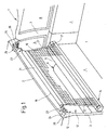
- Fig. 1 shows a broken area a rear area 1 of a station wagon.
- the rear area 1 is perspective about from the perspective of the broken left side Shown rear window and has a roof 2, which is supported on the side by two C-pillars 3.
- a rear side window 5 In front of the C pillar 3 is below the roof 2 and above one Side wall 4 a rear side window 5 while behind a further rear side window 6 is arranged in the C-pillar 3 is.
- the arrangement of the side windows 5 and 6 is on to think of the left side of the rear area in mirror image.
- Down the rear area 1 is essentially one flat loading area 7 completed.
- the rear seat back 9 Between the lower edge of the roof 2 and the upper edge the rear seat back 9 is an opening 12 through which a passenger compartment located in front of the rear seat back 9 the rear cargo area of the rear area 1 in Connection is established.
- the opening 12 is closed by a separating device 13.
- the separating device 13 includes a housing 14, a safety net 15 and one on the separation net 15 attached tie rod or strut 16.
- the housing 14 is an elongated, box-shaped housing, the one at the top with one over the entire Length continuous outlet slot 17 is provided.
- a drive device is located inside the housing 14 18 to a rotatably mounted winding shaft 19 in the sense the winding of the separation network 15 to bias.
- the housing 14 is detachable on the rear 11 of the rear seat back 9 attached.
- the separation network 15 has an edge with the winding shaft 19 connected and leads, starting from the winding shaft 19, through the outlet slot 17 out of the housing 14.
- the parallel to the winding shaft 19 edge of the separation network 15 is provided with a loop 21 which extends over the entire Width of the approximately trapezoidal separation network 15 passes.
- the strut 16 is in the loop.
- the mushroom-shaped heads 24 wear.
- the mushroom-shaped heads 24 are open Separating net 15 in T-shaped grooves 25 closed at the ends introduced by receiving pockets 26.
- the receiving pockets 26 are located just below the lower edge of the roof 2.
- Fig. 2 shows a highly schematic longitudinal section the structure of the housing 14. Belong to the housing 14 two cup-shaped end caps 27 and 28 and one in between extending tubular housing center piece 29, in which the outlet slot 17 is formed.
- the end cap 27 consists of a substantially flat Bottom 31, which is surrounded by a collar 32 on the edge is closed on all sides with the exception of the outlet slot 17 is.
- a molded cylindrical pin 33 From the inside i.e. the housing center piece 29 opposite side of the bottom 31 is a molded cylindrical pin 33 before, which as a bearing pin for the winding shaft 19 is used.
- the cap 28 at the other end basically has one similar structure and it consists of a bottom 34 to which a circumferential collar 35 is integrally formed, the again with the exception of the outlet slot 17 is trained.
- the winding shaft 19 is a cylindrical metal tube, which is essentially between the two end caps 27 and 28 extends. Stuck in the left end of the winding shaft 19 a reducer 36 with a coaxial to the winding shaft 19 Bore 37 rotatable on the journal 33 sits.
- drive device 18 It is already inside the winding shaft 19 mentioned drive device 18.
- this drive device include a first drive spring 38 in shape a clock spring, a second drive spring 39, likewise in the form of a coil spring, a coupling device 41, the host as a stroke limiting device, and a locking device 42.
- the second drive spring 39 generates a lower torque on the winding shaft 19 than the first Drive spring 38.
- the first drive spring 38 which acts as a drive spring for serves the winding shaft 19 is at one end at 43 with the journal 33 connected. Your other end is at 44 with that Coupling device 41 connected.
- the coupling device 41 consists of two cylinder pieces 45 and 46, which deal with face 47 and 48 and face each other are limited rotatable.
- the cylinder piece 45 has one smaller diameter than the inside diameter of the winding shaft 19 corresponds, so that the cylinder piece 45 opposite the winding shaft 19 is freely rotatable. On this piece of cylinder 45 the spring end 44 is attached.
- the cylinder piece 46 is with the help of impressions 49 rotatably held in the winding shaft 19 and in such a way that the two end faces 47 and 48 with face a small gap.
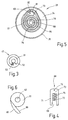
- Ring groove 51 In the flat end surface 47, as shown in FIG. 3, one concentric with the outer peripheral surface of the cylinder piece 45 Ring groove 51 contain almost a full circle describes.
- the groove 51 is through a narrow radially extending Web 52 interrupted.
- the cylinder piece 46 is provided with a driving lug 53, which dips into the groove 51. Limit this way the two cylinder pieces 45 and 46 together the stroke the drive spring 39.
- the cylinder piece 46 In the cylinder piece 46 is one to the winding shaft 19th contain coaxial bore 54 through which a cylindrical Coupling shaft 55 passes through.
- the coupling shaft 55 is on provided at its left end with a tapered section 56, the rotationally fixed in a coaxial bore 57 of the cylinder piece 45 is.
- the coupling shaft 55 and the cylinder piece 45 are in this way in the axial direction and in Circumferential direction firmly connected.
- the coupling shaft 55 extends coaxially to the winding shaft 19 and extends starting from the coupling device 41 in the direction of the end cap 28.
- the already mentioned second drive spring 39 which also is designed as a coil spring, with a End 58 on the coupling shaft 55 and with the other end 59 anchored to the cylinder piece 56. This is the mainspring 39 geared between the coupling shaft 55 and Winding shaft 19 effective.
- Winding shaft 19 To guide the coupling shaft 55 in the right end of the Winding shaft 19 contains winding shaft 19 in its end cap 28 adjacent end a filler 61 with a coaxial Bore 62 freely rotatable through the coupling shaft 55 leads through.
- the filler 61 is with the help of impressions 62 fixed in rotation in the winding shaft 19.
- the coupling shaft 55 projects with its right end the filler 61 axially over and carries on the axially protruding Part of a valve housing 63, which with the coupling shaft 55 is also firmly connected.
- On the sliding housing 63 is at the bottom 34 of the end cap 28 opposite Flat surface 64 formed a journal 65, the in a corresponding bearing bore 66, the blind bore is designed, stored.
- the blind bore 66 is located on the side facing the middle of the housing of the floor 34.
- a slide channel runs through the slide housing 63 67, which has a substantially rectangular cross section.
- the slide channel 67 extends radially and at right angles to the axis of the coupling shaft 55.
- the coupling shaft 55 Section is the slide channel 67 with a cylindrical Extension provided by the outer peripheral surface of the slide housing 63 up to the coupling shaft 55 enough. It also opens in this area using a slot to the end cap 28.
- a slide is slidably seated in the slide channel 67 68 as shown in Fig. 4.
- the slide 68 has a flat rectangular shape with a corresponding cross section the cross section of the slide channel 67.
- the slide 68 is from one side with a parallel flank Slot 69 provided, creating two legs 71 and 72 are formed, which at one end over a Back or bridge 73 are interconnected.
- the wide the slot 69 corresponds to the outer diameter of the coupling shaft 55 in the area of the slide channel 67.
- the slide 68 carries a guide pin in the area of the back 73 74, which is parallel to the axis of the coupling shaft 55 extends and towards the end cap 28 shows.
- the compression spring 75 in the form of a coil spring sits in the cylindrical extension already mentioned of the slide channel 67 and is supported at one end on the Outer circumference on the coupling shaft 55 and at the other ends on the bottom the slot 69 from.
- the spiral groove 67 opens at its radially inside lying end 77 in a cylindrical space 78, the concentrically surrounds the bearing bore 66.
- the depth of the groove 67 as its width is based on the geometry of the guide pin 74 adjusted.
- the groove 76 goes in at its radially outer end a pocket 79 facing the groove 76.
- the bag 79 is delimited radially outside by a wall 81, the distance between them from the wall of the groove is larger than the width of the groove 76 otherwise.
- a leaf spring is aligned with the free end of wall 81 82, which at 83 in the radially outer wall of the Nut 76 is anchored. Between the leaf spring 82 and the Wall 81 remains a gap corresponding to the diameter of the guide pin 74, and the leaf spring 82 crosses another endless groove 84, which is the outer wall the groove 76 surrounds egg-shaped.
- the leaf spring 82 serves as Soft, as will be explained further below.
- the filler 61 is an end view to recognize. Obviously, the filler 61 is included a tangential arm 85 which is one of the Axis of the winding shaft 19 facing straight guide surface 86 wears. The radially outer end of the guide surface 86 has a radial distance from the axis of the winding shaft 19, which is greater than the radial distance of the axis of the Bearing bore 66 from the most distant point of the outer closed egg-shaped groove 84.
- This retraction is caused by the drive spring 38 accomplished.
- the drive spring 38 is endeavors the winding shaft 19 based on the illustration so to rotate that the top of the winding shaft 19 from Viewer moved away.
- the take-up of the winding shaft 19 happens by the web 52 of the cylinder piece 45 the driver pin 53 applies, on that side as illustrated in FIG. 3.
- the pin 74 strikes in the pocket 79 and blocks a further rotation of the winding shaft 19. In this condition is a sufficient length of the Disconnect network 15 unwound from the winding shaft 19, which the User by catching the pin 74 in the pocket 79 is clearly signaled. The developed length is greater than the distance between the outlet slot 17 and corresponds to the exception pockets 26. If the user is outgoing a short distance from this position the separation network 15 can run back into the housing 14, the guide pin 74 strikes the opposite one Leaf spring 82 on. Since the compression spring 75 continues to strive the slide 68 together with the guide pin 74 to push outward, the guide pin 74 slides longitudinally the somewhat inclined leaf spring 82 against the outer wall the outer groove 84.
- the process can be broken down as would only the second drive spring 39 be effective, which over the coupling shaft 55, the slide 68, the guide pin 74 is supported on the end cap 28.
- the possible stroke over which the weaker second drive spring 39 is effective corresponds approximately to a 270 ° rotation the winding shaft 19 i.e. a length of about 70 mm to 110 mm based on the extended separating network 15. This stroke is sufficient to allow for distance tolerances between the Receiving pockets 26 and the anchoring of the housing 14 the rear seat back 8 and fluctuations in the ball diameter to compensate for the wound part of the separation network 15.
- the winding force comes in the first part of the run-in stroke only due to the weaker drive spring 39.
- the guide surface moves during this further retraction movement 68, which is rotatably coupled to the winding shaft 19 is towards the slide 68. After a corresponding one The tangentially running guide surface 86 becomes the stroke the slide 68 engage.
- the guide surface 86 moves if it were on the 5 are projected when winding of the separation network 15 counterclockwise and they would projected onto the illustration of FIG. 5 from the top left to the right under. This creates them on the Slider 68 a radially inward force that is greater than the radially outward force of the Compression spring 75.
- the guide surface 86 is against the action of Compression spring 75 push the slide 68 radially inwards, the guide pin 74 on the inclined leaf spring 82 slides radially inwards and into the radially outside the beginning of the spiral groove 76. This blocks the coupling shaft 55 and it is driven by the much stronger one Turn first drive spring 38 counterclockwise until the web 52 again as shown in Fig. 3 on the driver pin 53 comes to the plant. During this transition pulls the stronger drive spring 38 the weaker drive spring 39 again, which occurred during the previous introductory movement has increasingly relaxed.
- the spiral groove 76 works the spiral groove 76 together with the pocket 79 as one Counter showing the number of revolutions of the winding shaft 19 recorded in order to signal to the user that a sufficient quantity of separation network 15 from the winding shaft 19 is pulled off for a comfortable hanging of the pull rod To allow 16 in the receiving pockets 26. If those Counting function is not desired because of the signaling the sufficiently withdrawn amount of separation network 15 different takes place, the entire structure, which is the spiral Groove 76 defined on the inside of the end cap 28 omitted become. It would be enough if just a stop corresponding to the leaf spring 82 would be present.
- the user needs the full load space of the car and therefore wants to fold the back seat back 9 and, if necessary also set up the rear bench 8, the housing 14 near the floor of the cargo hold with the result that a larger amount of separation network 15 is required to close the opening to the passenger compartment.
- the separation network 15 from the Pulled out the housing 14 as previously described until the Guide pin 74 catches in the pocket 79.
- the user the voltage in the separation network 15 now decreases somewhat and enables the guide pin 74 along the leaf spring 82 against the outer wall of the outer guide groove 84 slide.
- the user can now continue to disconnect the network 15 Pull out the housing 14, whereby the guide pin 74 runs through the outer groove 84.
- the leaf spring 82 is like this designed that the path of movement for the guide pin 74 releases if this is from the left in relation to FIG. 5 here from the back of the leaf spring 82 approaches.
- the leaf spring 82 folds over like a switch and leaves pass the guide pin 74. In this way, a any quantity of separation network 15 from the winding shaft 18 subtracted from.
- the separation network 15 When the separation network 15 runs in, it moves the guide pin 74 counterclockwise through the groove 84 and immediately after a maximum of one revolution of the winding shaft 18 on the leaf spring 82 with the help of Guide surface 86 in the inner spiral Groove 67 deflected. After a further two and a half turns the guide pin 74 is in the cylindrical Area 78 so that the winding shaft 18 is unimpeded can make as many revolutions as the entire withdrawn amount of separation net 15 wound up.
- the two springs 38 and 39 are kinematic connected in series.
- the second spring 39 is weaker and its overstretching when the separating network 15 is pulled out limited by the coupling device 41, which is a relative rotation between the coupling shaft 55 and the winding shaft 19 of not quite 360 °.
- the coupling device 41 which is a relative rotation between the coupling shaft 55 and the winding shaft 19 of not quite 360 °.
- the weaker retraction force take effect according to the second drive spring 39 can.
- a lower actuation force for the separation network 15 can not only be achieved through the series connection by two drive springs, but also by a controlled one Parallel connection of two drive springs so that in the area of interest of the separation network 15 a second spring is connected in parallel, the part of the retraction force of the actual drive spring picks up.
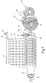
- Such an embodiment is highly schematic shown in Fig. 7, wherein already described and Kinematically similar components with the same reference number are provided.
- the winding shaft 19 in a known manner only by a drive spring, which corresponds, for example, to the drive spring 38, rotated.
- a drive spring which corresponds, for example, to the drive spring 38, rotated.
- One end of the drive spring 38 is directly attached to the housing 14 while the other End is connected directly to the winding shaft 19.
- a Sliding housing 63 available, but now rigid with the Winding shaft 19 is connected.
- the sliding housing 63 is the slide 68 guided, the guide pin 74 which is spiral running groove 76 senses.
- the groove housing 91 is made by means of a spiral spring 93 biased into an end position within the end cap 28 which corresponds to a position of the grooves 76 and 84 as shown in FIG. 5 is shown.
- the spiral spring 93 is kinematically between the groove housing 91 and the end cap, not shown 28 effective. Contrary to the action of the spring 83, the Groove housing 91 in turn projected onto the representation 5 are rotated counterclockwise according to FIG corresponding to an angle of rotation of slightly less than 360 °.
- the torque generated by the coil spring 93 is less than the torque from the drive spring 38 is generated when such an amount of separation network 15 is subtracted is that the pull rod 16 conveniently into the receiving pockets 26 can be hung.
- the guide pin is in the retracted state 74 in the cylindrical interior 38 and the coil spring 93 biases the groove housing 91 into the end position, see above that there is a configuration according to the illustration 5 results.
- the guide pin 74 moves along the spiral Groove 76 outwards until it catches in pocket 79.
- the user in turn leaves the voltage in the disconnection network 15 a little bit so that the clock spring 38 the winding shaft 19 in Can move winding sense, whereby the guide pin 74th along the leaf spring 82 against the outer wall of the groove 84 presses the outer wall of the groove housing 91 at the same time is.
- the winding shaft 19 is in the winding direction rotated because the mainspring 38 generates a greater torque than the counteracting Coil spring 93.
- the guide pin 74 takes the groove housing 91 with, i.e. based on Fig. 5 it would be the groove housing Turn 91 counterclockwise. In the course of Rotation of the guide pin 74 abuts a dashed drawn ramp 94, which is stationary in the end cap 28 is appropriate.
- the guide ramp 94 presses the guide pin 74 radially inward, making it along the leaf spring 82 finds back in the spiral groove 76. Thereby the effect of the compensating spring 93 is canceled, corresponding to the groove housing 91 in the starting position Fig. 7 turns back.
- the winding shaft 18 is now only still by the action of the drive spring 38 in revolutions transferred.
- a separating device 13 14 is in a housing a winding shaft 19 rotatably arranged.
- a separation network 15 can be wound up, which in the space between the housing 14 of the separator 13 and the headliner of a car can be spanned.
- a drive device 18 Since the clock spring 19 with increasing deduction of the Isolation network 15 generates a greater torque that the User must counteract is a drive device 18 provided, which ensures that from a predetermined Extension length of the drive torque for the winding shaft 19 is switched to a reduced level.
- This toggle is either accomplished by adding a second weaker one Drive spring 39 is made effective or by the drive spring 38 for the winding shaft 19 a second drive spring 93 is connected in parallel. Both auxiliary springs 39, 93 work only over a limited range of rotation of the winding shaft 19. After crossing this area in the winding sense the full winding force of the main spring 38 effective.
Landscapes
- Engineering & Computer Science (AREA)
- Mechanical Engineering (AREA)
- Aviation & Aerospace Engineering (AREA)
- Transportation (AREA)
- Vehicle Step Arrangements And Article Storage (AREA)
- Body Structure For Vehicles (AREA)
- Operating, Guiding And Securing Of Roll- Type Closing Members (AREA)
Abstract
Description
Claims (23)
- Trenneinrichtung (9) für Kraftfahrzeuge, insbesondere für Kombi-PKW, um bei einem Auffahrunfall Gegenstände aus einem Koffer- oder Gepäckraum daran zu hindern, in den Fahrgastraum geschleudert zu werden,mit einem Gehäuse (14), das einen parallel zu der Länge des Gehäuses (14) sich erstreckenden Auslaufschlitz (17) aufweist,mit einer in dem Gehäuse (14) drehbar gelagerten Wickelwelle (19),mit einem Trenn-Netz (15), das durch den Auslaufschlitz (17) verläuft und das zwei voneinander beabstandete Längskanten aufweist, von denen eine an der Wickelwelle (19) befestigt ist und die andere mit einem Zugstab (16) verbunden ist, der in der Karosserie einzuhängen ist, und,mit einer der Wickelwelle (19) zugeordneten Antriebseinrichtung (18), um auf die Wickelwelle (19) im Sinne eines Aufwickelns des Trenn-Netzes (15) vorzuspannen und dadurch eine Rückzugskraft für das Trenn-Netz (15) zu erzeugen,
wobei die Antriebseinrichtung (18) wenigstens zwei Betriebszustände aufweist, von denen der eine einer stärkeren Rückzugskraft und der andere einer schwächeren Rückzugkraft entspricht und von denen der eine Zustand in einem Anfangsbereich zwischen der vollständig eingezogenen Stellung des Trenn-Netzes (15) bis zu einer ersten vorgegebenen Auszugslänge und der andere beginnend bei der ersten vorgegebenen Auszugslänge wirksam ist. - Trenneinrichtung nach Anspruch 1, dadurch gekennzeichnet, dass der andere Betriebszustand einen Auszugsbereich umfasst, der bei der ersten vorgegebenen Auszugslänge beginnt und an einer Stelle endet, die einer zweiten vorgegebenen Auszugslänge entspricht, die kürzer ist als die erste vorgegebene Auszugslänge.
- Trenneinrichtung nach Anspruch 1, dadurch gekennzeichnet, dass bei der vorgegebenen Auszugslänge das Trenn-Netz (15) etwas länger ausgezogen ist als es zum Einhängen der Zugstange (16) in der Karosserie erforderlich ist.
- Trenneinrichtung nach Anspruch 1, dadurch gekennzeichnet, dass die Antriebseinrichtung (18) wenigstens zwei Antriebsfedern (38,39,93) aufweist.
- Trenneinrichtung nach Anspruch 1, dadurch gekennzeichnet, dass die Antriebsfedern (38,39,93) derart gestaltet sind, dass sie eine unterschiedliche Rückzugskraft erzeugen.
- Trenneinrichtung nach Anspruch 1, dadurch gekennzeichnet, dass bei einer Auszugslänge des Trenn-Netzes (15) größer als die vorgegebene Auszugslänge lediglich die eine Feder (39) im Sinne der Erzeugung einer Rückzugskraft wirksam ist.
- Trenneinrichtung nach Anspruch 1, dadurch gekennzeichnet, dass nach dem Überschreiten der vorgegebenen Auszugslänge die Antriebsfeder (38) mit der größeren Rückzugskraft unwirksam gemacht ist und lediglich die Antriebsfeder (39) mit der kleineren Rückzugskraft an der Wickelwelle (19) wirksam ist.
- Trenneinrichtung nach Anspruch 1, dadurch gekennzeichnet, dass bei einer Auszugslänge des Trenn-Netzes (15) größer als die vorgegebene Auszugslänge beide Antriebsfedern (38,93) im Sinne der Erzeugung einer verminderten Rückzugskraft wirksam sind.
- Trenneinrichtung nach Anspruch 1, dadurch gekennzeichnet, dass nach dem Überschreiten der vorgegebenen Auszuglänge die zweite Antriebsfeder (93) zusätzlich wirksam gemacht ist, derart dass sie die Rückzugskraft der ersten Antriebsfeder (38) teilweise aufhebt.
- Trenneinrichtung nach Anspruch 1, dadurch gekennzeichnet, dass wenigstens eine der Antriebsfedern (38,39) durch eine Schraubenfeder gebildet ist, die in der Wickelwelle (19) untergebracht ist.
- Trenneinrichtung nach Anspruch 1, dadurch gekennzeichnet, dass beide Antriebsfedern (38,39) Schraubenfedern sind, die in der Wickelwelle (19) untergebracht sind.
- Trenneinrichtung nach Anspruch 1, dadurch gekennzeichnet, dass wenigstens ein der Antriebsfedern (93) durch eine Spiralfeder gebildet ist.
- Trenneinrichtung nach Anspruch 12, dadurch gekennzeichnet, dass sich die Spiralfeder (93) neben der Wickelwelle () befindet.
- Trenneinrichtung nach Anspruch 1, dadurch gekennzeichnet, dass die Antriebseinrichtung (18) eine Zähleinrichtung (76) für die Anzahl der Umdrehungen bzw. Teilumdrehungen der Wickelwelle (19) aufweist.
- Trenneinrichtung nach Anspruch 1, dadurch gekennzeichnet, dass eine lösbare Sperreinrichtung (42) vorgesehen ist, die zumindest nach dem Erreichen der vorgegebenen Auszugslänge die Rückzugskraft von einer der Antriebsfedern (38) aufnimmt.
- Trenneinrichtung nach den Ansprüchen 14 und 15, dadurch gekennzeichnet, dass die Sperreinrichtung (42) mit der Zähleinrichtung (74) zusammenwirkt.
- Trenneinrichtung nach Anspruch 1, dadurch gekennzeichnet, dass eine lösbare Koppeleinrichtung (91) vorgehen ist, die nach dem Erreichen der vorgegebenen Auszugslänge die Rückzugskraft der einen Antriebsfeder (38) mit der Rückzugskraft der anderen Antriebsfeder (93) kombiniert.
- Trenneinrichtung nach den Ansprüchen 14 und 17, dadurch gekennzeichnet, dass die Koppeleinrichtung (91) mit der Zähleinrichtung (76) zusammenwirkt.
- Trenneinrichtung nach Anspruch 14, 15 oder 17, dadurch gekennzeichnet, dass die Sperreinrichtung (42) oder die Koppeleinrichtung (91) oder die Zähleinrichtung (76) eine Nut (76) und ein Abtastelement (74) aufweist, das in der Nut (76) läuft, und dass entweder die Nut (76) oder das Abtastelement (74) drehfest mit der Wickelwelle (19) verbunden sind.
- Trenneinrichtung nach Anspruch 1, dadurch gekennzeichnet, dass eine der Antriebsfedern (93) mit der spiralförmigen Nut (76) gekoppelt ist.
- Trenneinrichtung nach Anspruch 1, dadurch gekennzeichnet, dass die spiralförmige Nut (76) ortsfest in dem Gehäuse (14) angeordnet ist.
- Trenneinrichtung nach Anspruch 1, dadurch gekennzeichnet, dass mit der Wickelwelle (19) ein Auslöseelement (86) für die Sperreinrichtung (42) drehfest verbunden ist.
- Trenneinrichtung nach Anspruch 1, dadurch gekennzeichnet, dass ein Ende einer Antriebsfeder (38) mit einem Ende der anderen Antriebsfeder (39) über eine Kulisseneinrichtung (41) verbunden ist, die eine begrenzte Relativbewegung zwischen den so verbundenen Ende der Antriebsfedern (38,39) ermöglicht.
Applications Claiming Priority (2)
| Application Number | Priority Date | Filing Date | Title |
|---|---|---|---|
| DE19927384A DE19927384C1 (de) | 1999-06-16 | 1999-06-16 | Trenneinrichtung mit variabler Rückzugskraft |
| DE19927384 | 1999-06-16 |
Publications (3)
| Publication Number | Publication Date |
|---|---|
| EP1060956A2 true EP1060956A2 (de) | 2000-12-20 |
| EP1060956A3 EP1060956A3 (de) | 2002-10-09 |
| EP1060956B1 EP1060956B1 (de) | 2006-01-18 |
Family
ID=7911385
Family Applications (1)
| Application Number | Title | Priority Date | Filing Date |
|---|---|---|---|
| EP00111765A Expired - Lifetime EP1060956B1 (de) | 1999-06-16 | 2000-06-03 | Trenneinrichtung mit variabler Rückzugskraft |
Country Status (5)
| Country | Link |
|---|---|
| US (1) | US6279639B1 (de) |
| EP (1) | EP1060956B1 (de) |
| JP (1) | JP2001010410A (de) |
| KR (1) | KR100653112B1 (de) |
| DE (2) | DE19927384C1 (de) |
Cited By (1)
| Publication number | Priority date | Publication date | Assignee | Title |
|---|---|---|---|---|
| EP1808342A3 (de) * | 2006-01-02 | 2008-03-19 | BOS GmbH & Co. KG | Schutzvorrichtung für ein Kraftfahrzeug |
Families Citing this family (25)
| Publication number | Priority date | Publication date | Assignee | Title |
|---|---|---|---|---|
| JP2001505159A (ja) * | 1996-12-06 | 2001-04-17 | バウマイスター・ウント・オストラー・ゲーエムベーハー・ウント・コンパニー | 取扱いが簡単な安全ネット装置 |
| DE10056671C1 (de) * | 2000-11-09 | 2002-06-06 | Bos Gmbh | Trennvorrichtung für ein Kraftfahrzeug |
| DE10132080C1 (de) * | 2001-07-05 | 2002-07-25 | Butz Peter Verwaltung | Schutz- und/oder Abdeckrollo für Fahrzeuge |
| DE10132082C1 (de) * | 2001-07-05 | 2002-07-18 | Butz Peter Verwaltung | Schutz- und/oder Abdeckrollo für Fahrzeuge |
| DE10242510B4 (de) * | 2002-09-12 | 2005-12-08 | Bos Gmbh & Co. Kg | Kfz-Sicherheitseinrichtung, insbesondere Trennnetz |
| US6962382B2 (en) * | 2003-05-23 | 2005-11-08 | David Scarlett | Barrier system |
| DE102004036948B3 (de) | 2004-07-29 | 2006-03-23 | Bos Gmbh & Co. Kg | Gekrümmtes Fensterrollo mit innen liegendem Federwiderlager |
| US7717156B2 (en) * | 2004-12-28 | 2010-05-18 | Barnes Group Inc. | Device for creating an adjustable angular force |
| DE102005032470B3 (de) * | 2005-07-08 | 2007-03-08 | Bos Gmbh & Co. Kg | Laderaumschutzvorrichtung für ein Kraftfahrzeug |
| US7549457B2 (en) * | 2005-08-22 | 2009-06-23 | Irvin Automotive Products, Inc. | Silicone shade |
| DE102006005673B4 (de) * | 2006-02-01 | 2010-08-05 | Bos Gmbh & Co. Kg | Fahrzeugladeraum mit einer Laderaumabdeckung |
| US7287796B2 (en) * | 2006-02-22 | 2007-10-30 | Ford Global Technologies, Llc | Integrated cargo net for a vehicle |
| US7477824B2 (en) * | 2006-04-05 | 2009-01-13 | Adc Telecommunications, Inc. | Universal bracket for mounting a drop terminal |
| US7779887B2 (en) * | 2007-01-10 | 2010-08-24 | Irvin Automotive Products, Inc. | Rotating end cap |
| US8672016B2 (en) * | 2007-01-10 | 2014-03-18 | Irvin Automotive Products, Inc. | Folding end cap |
| GB0700967D0 (en) * | 2007-01-18 | 2007-02-28 | Louver Life Ltd | Window coverings |
| DE102007012280A1 (de) | 2007-03-09 | 2008-09-11 | Bos Gmbh & Co. Kg | Rollosystem |
| US20090074993A1 (en) * | 2007-09-18 | 2009-03-19 | Gm Global Technology Operations, Inc. | Active material activated cover |
| US9707003B2 (en) * | 2007-10-02 | 2017-07-18 | Covidien Lp | Articulating surgical instrument |
| US7591296B2 (en) * | 2007-10-17 | 2009-09-22 | Irvin Automotive Products, Inc. | Two piece removable end cap |
| KR100866344B1 (ko) * | 2008-05-07 | 2008-10-31 | 김성철 | 롤 블라인드 |
| US9156334B1 (en) * | 2014-06-30 | 2015-10-13 | Nissan North America, Inc. | Vehicle body structure |
| DE102016115667A1 (de) | 2016-08-24 | 2018-03-01 | Dr. Ing. H.C. F. Porsche Aktiengesellschaft | Vorrichtung zur Befestigung eines Fangnetzes in einem Fahrzeug |
| CN108376513B (zh) * | 2018-04-26 | 2024-02-13 | 广东电网有限责任公司 | 收卷装置及安全收卷装置 |
| CN109592236B (zh) * | 2018-11-26 | 2023-11-28 | 大连派欧机电设备有限公司 | 一种物联网货物运输装置及方法 |
Family Cites Families (9)
| Publication number | Priority date | Publication date | Assignee | Title |
|---|---|---|---|---|
| US1709305A (en) * | 1923-05-19 | 1929-04-16 | Kinnear Mfg Co | Fire-resisting curtain |
| US4139231A (en) * | 1978-05-08 | 1979-02-13 | Irvin Industries Inc. | Automobile rear compartment cover |
| US4222601A (en) * | 1978-10-16 | 1980-09-16 | Irvin Industries Inc. | Automobile compartment cover |
| US5275223A (en) * | 1992-02-28 | 1994-01-04 | Sebastian Magro | Support roller provided with roll-up mechanism for rolling doors, gates and the like |
| US5224748A (en) * | 1992-04-07 | 1993-07-06 | Takata, Inc. | Motor vehicle security shade with guide track |
| US5437324A (en) * | 1994-01-19 | 1995-08-01 | Newell Operating Company | Shade with variable load braking and lift assist |
| JP3075687B2 (ja) * | 1995-10-18 | 2000-08-14 | 本田技研工業株式会社 | 車両用トノーカバー装置 |
| US5711568A (en) * | 1996-02-05 | 1998-01-27 | Diem; D.W. | Retractable cargo cover |
| ES2167533T3 (es) * | 1996-07-23 | 2002-05-16 | Pei Protezioni Elaborazioni | Rodillo para rebobinar y tensar un elemento flexible tal como una lamina de tela, compuerta o similar, en particular para proteccion de maquinas. |
-
1999
- 1999-06-16 DE DE19927384A patent/DE19927384C1/de not_active Expired - Fee Related
-
2000
- 2000-06-03 DE DE50012063T patent/DE50012063D1/de not_active Expired - Lifetime
- 2000-06-03 EP EP00111765A patent/EP1060956B1/de not_active Expired - Lifetime
- 2000-06-14 JP JP2000177848A patent/JP2001010410A/ja active Pending
- 2000-06-15 US US09/594,616 patent/US6279639B1/en not_active Expired - Fee Related
- 2000-06-16 KR KR1020000033183A patent/KR100653112B1/ko not_active Expired - Fee Related
Non-Patent Citations (1)
| Title |
|---|
| None |
Cited By (1)
| Publication number | Priority date | Publication date | Assignee | Title |
|---|---|---|---|---|
| EP1808342A3 (de) * | 2006-01-02 | 2008-03-19 | BOS GmbH & Co. KG | Schutzvorrichtung für ein Kraftfahrzeug |
Also Published As
| Publication number | Publication date |
|---|---|
| US6279639B1 (en) | 2001-08-28 |
| KR100653112B1 (ko) | 2006-12-04 |
| JP2001010410A (ja) | 2001-01-16 |
| EP1060956B1 (de) | 2006-01-18 |
| KR20010007409A (ko) | 2001-01-26 |
| DE19927384C1 (de) | 2000-12-07 |
| DE50012063D1 (de) | 2006-04-06 |
| EP1060956A3 (de) | 2002-10-09 |
Similar Documents
| Publication | Publication Date | Title |
|---|---|---|
| EP1060956B1 (de) | Trenneinrichtung mit variabler Rückzugskraft | |
| EP1609647B1 (de) | Fensterrollo mit Deckel auf dem Auszugsschlitz | |
| DE10228028B3 (de) | Heckscheibenrollo mit Hubkassette | |
| EP1524153B1 (de) | Schutzvorrichtung für einen Laderaum eines Kraftfahrzeugs | |
| DE19906912C1 (de) | Überroll-Schutzsystem für Kraftfahrzeuge | |
| DE1781432C3 (de) | Selbstsperrende Rückziehvorrichtung für Sicherheitsgurte | |
| EP1128992A1 (de) | Faltbare trenneinrichtung | |
| DE2900104A1 (de) | Gehaeusezusammenstellung fuer eine vorgespannte feder einer sicherheitsgurteinziehvorrichtung | |
| EP1205361B1 (de) | Trennvorrichtung für ein Kraftfahrzeug | |
| EP1844984A2 (de) | Laderaum für ein Kraftfahrzeug mit einer Schutzvorrichtung | |
| EP1316483B1 (de) | Gurtstraffer | |
| DE2250370A1 (de) | Schutzvorrichtung fuer fahrzeuginsassen | |
| DE19849927C2 (de) | Sicherheitseinrichtung für Fahrzeuge, insbesondere Laderaum-Trennvorrichtung für Kraftwagen, wie zum Beispiel für Kombinations-Personenkraftwagen o. dgl. | |
| DE2364754A1 (de) | Gelenk fuer regelbare sitzrueckenlehnen | |
| DE2204623A1 (de) | Kraftfahrzeug mit mechanisch betaetigbarem dreipunkt-sicherheitsgurt | |
| DE102014003440B3 (de) | Laderaumabdeckung für ein Fahrzeug | |
| DE19745154A1 (de) | Rückhaltevorrichtung für die Insassen eines Fahrzeugs, insbesondere eines Kraftfahrzeuges | |
| EP1776257B9 (de) | Überrollschutzsystem für kraftfahrzeuge mit versenkbarem dach | |
| DE2730326A1 (de) | Vorrichtung zum zurueckziehen und aufrollen eines sicherheitsgurtes | |
| DE2211426A1 (de) | Sicherheitsgurt für Kraftfahrzeuge | |
| DE602004008238T2 (de) | Sicherheitsvorrichtung | |
| DE2946717A1 (de) | Vorrichtung zum spannen eines gurts | |
| DE2304183A1 (de) | Mechanik fuer sicherheitsgurte | |
| EP1808342A2 (de) | Schutzvorrichtung für ein Kraftfahrzeug | |
| EP0635407A1 (de) | Sicherheitsgurtanordnung für Kraftfahrzeuge mit Straffervorrichtung |
Legal Events
| Date | Code | Title | Description |
|---|---|---|---|
| PUAI | Public reference made under article 153(3) epc to a published international application that has entered the european phase |
Free format text: ORIGINAL CODE: 0009012 |
|
| AK | Designated contracting states |
Kind code of ref document: A2 Designated state(s): AT BE CH CY DE DK ES FI FR GB GR IE IT LI LU MC NL PT SE |
|
| AX | Request for extension of the european patent |
Free format text: AL;LT;LV;MK;RO;SI |
|
| PUAL | Search report despatched |
Free format text: ORIGINAL CODE: 0009013 |
|
| AK | Designated contracting states |
Kind code of ref document: A3 Designated state(s): AT BE CH CY DE DK ES FI FR GB GR IE IT LI LU MC NL PT SE |
|
| AX | Request for extension of the european patent |
Free format text: AL;LT;LV;MK;RO;SI |
|
| 17P | Request for examination filed |
Effective date: 20030307 |
|
| AKX | Designation fees paid |
Designated state(s): DE FR GB IT |
|
| GRAP | Despatch of communication of intention to grant a patent |
Free format text: ORIGINAL CODE: EPIDOSNIGR1 |
|
| GRAC | Information related to communication of intention to grant a patent modified |
Free format text: ORIGINAL CODE: EPIDOSCIGR1 |
|
| GRAS | Grant fee paid |
Free format text: ORIGINAL CODE: EPIDOSNIGR3 |
|
| GRAA | (expected) grant |
Free format text: ORIGINAL CODE: 0009210 |
|
| AK | Designated contracting states |
Kind code of ref document: B1 Designated state(s): DE FR GB IT |
|
| REG | Reference to a national code |
Ref country code: GB Ref legal event code: FG4D Free format text: NOT ENGLISH |
|
| REF | Corresponds to: |
Ref document number: 50012063 Country of ref document: DE Date of ref document: 20060406 Kind code of ref document: P |
|
| GBT | Gb: translation of ep patent filed (gb section 77(6)(a)/1977) |
Effective date: 20060426 |
|
| ET | Fr: translation filed | ||
| PLBE | No opposition filed within time limit |
Free format text: ORIGINAL CODE: 0009261 |
|
| STAA | Information on the status of an ep patent application or granted ep patent |
Free format text: STATUS: NO OPPOSITION FILED WITHIN TIME LIMIT |
|
| 26N | No opposition filed |
Effective date: 20061019 |
|
| PGFP | Annual fee paid to national office [announced via postgrant information from national office to epo] |
Ref country code: IT Payment date: 20080623 Year of fee payment: 9 |
|
| PGFP | Annual fee paid to national office [announced via postgrant information from national office to epo] |
Ref country code: GB Payment date: 20080620 Year of fee payment: 9 |
|
| PGFP | Annual fee paid to national office [announced via postgrant information from national office to epo] |
Ref country code: FR Payment date: 20090615 Year of fee payment: 10 |
|
| GBPC | Gb: european patent ceased through non-payment of renewal fee |
Effective date: 20090603 |
|
| PG25 | Lapsed in a contracting state [announced via postgrant information from national office to epo] |
Ref country code: GB Free format text: LAPSE BECAUSE OF NON-PAYMENT OF DUE FEES Effective date: 20090603 |
|
| REG | Reference to a national code |
Ref country code: FR Ref legal event code: ST Effective date: 20110228 |
|
| PG25 | Lapsed in a contracting state [announced via postgrant information from national office to epo] |
Ref country code: IT Free format text: LAPSE BECAUSE OF NON-PAYMENT OF DUE FEES Effective date: 20090603 |
|
| PG25 | Lapsed in a contracting state [announced via postgrant information from national office to epo] |
Ref country code: FR Free format text: LAPSE BECAUSE OF NON-PAYMENT OF DUE FEES Effective date: 20100630 |
|
| PGFP | Annual fee paid to national office [announced via postgrant information from national office to epo] |
Ref country code: DE Payment date: 20140509 Year of fee payment: 15 |
|
| REG | Reference to a national code |
Ref country code: DE Ref legal event code: R119 Ref document number: 50012063 Country of ref document: DE |
|
| PG25 | Lapsed in a contracting state [announced via postgrant information from national office to epo] |
Ref country code: DE Free format text: LAPSE BECAUSE OF NON-PAYMENT OF DUE FEES Effective date: 20160101 |