EP1060788A1 - Réacteur catalytique isotherme pour effectuer des réactions exothermes ou endothermes hétérogènes - Google Patents
Réacteur catalytique isotherme pour effectuer des réactions exothermes ou endothermes hétérogènes Download PDFInfo
- Publication number
- EP1060788A1 EP1060788A1 EP99111538A EP99111538A EP1060788A1 EP 1060788 A1 EP1060788 A1 EP 1060788A1 EP 99111538 A EP99111538 A EP 99111538A EP 99111538 A EP99111538 A EP 99111538A EP 1060788 A1 EP1060788 A1 EP 1060788A1
- Authority
- EP
- European Patent Office
- Prior art keywords
- tubes
- catalytic bed
- reactor according
- tube
- reactor
- Prior art date
- Legal status (The legal status is an assumption and is not a legal conclusion. Google has not performed a legal analysis and makes no representation as to the accuracy of the status listed.)
- Withdrawn
Links
Images


Classifications
-
- B—PERFORMING OPERATIONS; TRANSPORTING
- B01—PHYSICAL OR CHEMICAL PROCESSES OR APPARATUS IN GENERAL
- B01J—CHEMICAL OR PHYSICAL PROCESSES, e.g. CATALYSIS OR COLLOID CHEMISTRY; THEIR RELEVANT APPARATUS
- B01J8/00—Chemical or physical processes in general, conducted in the presence of fluids and solid particles; Apparatus for such processes
- B01J8/02—Chemical or physical processes in general, conducted in the presence of fluids and solid particles; Apparatus for such processes with stationary particles, e.g. in fixed beds
- B01J8/0285—Heating or cooling the reactor
-
- B—PERFORMING OPERATIONS; TRANSPORTING
- B01—PHYSICAL OR CHEMICAL PROCESSES OR APPARATUS IN GENERAL
- B01J—CHEMICAL OR PHYSICAL PROCESSES, e.g. CATALYSIS OR COLLOID CHEMISTRY; THEIR RELEVANT APPARATUS
- B01J8/00—Chemical or physical processes in general, conducted in the presence of fluids and solid particles; Apparatus for such processes
- B01J8/02—Chemical or physical processes in general, conducted in the presence of fluids and solid particles; Apparatus for such processes with stationary particles, e.g. in fixed beds
- B01J8/0207—Chemical or physical processes in general, conducted in the presence of fluids and solid particles; Apparatus for such processes with stationary particles, e.g. in fixed beds the fluid flow within the bed being predominantly horizontal
- B01J8/0214—Chemical or physical processes in general, conducted in the presence of fluids and solid particles; Apparatus for such processes with stationary particles, e.g. in fixed beds the fluid flow within the bed being predominantly horizontal in a cylindrical annular shaped bed
-
- F—MECHANICAL ENGINEERING; LIGHTING; HEATING; WEAPONS; BLASTING
- F28—HEAT EXCHANGE IN GENERAL
- F28D—HEAT-EXCHANGE APPARATUS, NOT PROVIDED FOR IN ANOTHER SUBCLASS, IN WHICH THE HEAT-EXCHANGE MEDIA DO NOT COME INTO DIRECT CONTACT
- F28D7/00—Heat-exchange apparatus having stationary tubular conduit assemblies for both heat-exchange media, the media being in contact with different sides of a conduit wall
- F28D7/04—Heat-exchange apparatus having stationary tubular conduit assemblies for both heat-exchange media, the media being in contact with different sides of a conduit wall the conduits being spirally coiled
-
- B—PERFORMING OPERATIONS; TRANSPORTING
- B01—PHYSICAL OR CHEMICAL PROCESSES OR APPARATUS IN GENERAL
- B01J—CHEMICAL OR PHYSICAL PROCESSES, e.g. CATALYSIS OR COLLOID CHEMISTRY; THEIR RELEVANT APPARATUS
- B01J2208/00—Processes carried out in the presence of solid particles; Reactors therefor
- B01J2208/00008—Controlling the process
- B01J2208/00017—Controlling the temperature
- B01J2208/00106—Controlling the temperature by indirect heat exchange
- B01J2208/00115—Controlling the temperature by indirect heat exchange with heat exchange elements inside the bed of solid particles
- B01J2208/00141—Coils
-
- F—MECHANICAL ENGINEERING; LIGHTING; HEATING; WEAPONS; BLASTING
- F28—HEAT EXCHANGE IN GENERAL
- F28F—DETAILS OF HEAT-EXCHANGE AND HEAT-TRANSFER APPARATUS, OF GENERAL APPLICATION
- F28F2210/00—Heat exchange conduits
- F28F2210/10—Particular layout, e.g. for uniform temperature distribution
Definitions
- the present invention relates to an isothermal reactor for carrying out exothermic or endothermic heterogeneous reactions, comprising:
- isothermal reactor it is intended to mean a reactor wherein the temperature within the catalytic bed(s) where the reaction takes place is maintained essentially constant, such reaction may be either exothermic or endothermic.
- Reactors of this kind may for example be employed in the synthesis of chemicals such as methanol or formaldehyde (strongly exothermic reactions) or styrene (strongly endothermic reactions).
- isothermal reactors have been proposed in the field, which are provided with a catalytic bed of radial type comprising a large number of vertical straight tubes within it for drawing off or supplying heat.
- DE-A-3 318 098 discloses an isothermal reactor for carrying out exothermic or endothermic heterogeneous synthesises wherein the gaseous reactants pass through the catalytic bed radially and come in contact with a plurality of vertical tubes arranged within said bed.
- the tubes for drawing off or supplying the heat extends helically about a central collector for the outlet of the reacted gases from the reactor.
- the bundle of helicoidal tubes extends vertically between opposed upper and lower tube plates, wherein such tubes are twisted round each other.
- the isothermal reactor with an helicoidal tube bundle disclosed in DE-A-3 318 098 has a number of drawbacks, which are set forth hereinbelow.
- the arrangement of the tubes as a helicoidal tube bundle - although better than the arrangement of vertical straight tubes - does not match effectively the temperature curve of the flow of gaseous reactants that pass through the catalytic bed with a radial motion.
- the outer helicoidal tubes are crossed by a gas that has just started to react, and is thus relatively cold, whereas the helicoidal tubes which are closer to the core are crossed by a gas at higher and higher temperature that exchanges with them an ever increasing amount of heat until a point is reached, where the temperature of the reaction gas is at its maximum. From there on, the temperature decreases and hence the amount of heat which is absorbed by the helicoidal tubes arranged next to the gas outlet wall of the catalytic bed is progressively smaller. (see DE-A-3 318 098, fig. 3).
- each helicoidal tube receives a different amount of heat and must stand a different thermal load. This causes a bad distribution of temperature within the catalytic bed detrimental for the heat exchange efficiency.
- the helicoidal tubes in contact with the gaseous reactants at low temperature are subjected to a small thermal load, which means a low degree of vaporisation of the water with ensuing low outlet velocity and therefore high water flow rates (calculated as mass flow rates) .
- the helicoidal tubes in contact with the gaseous reactants at high temperature are instead subjected to a great thermal load, which means a high degree of vaporisation of the water with ensuing high outlet velocity and therefore low water flow rates (calculated as mass flow rates).
- a further disadvantage of the reactor according to the prior art is given by the high structural complexity deriving from the helicoidal arrangement of the tube bundle that requires high investment and maintenance costs.
- the problem underlying the present invention is that of providing an isothermal reactor for carrying out exothermic or endothermic heterogeneous reactions which is easy to realise, reliable and requires low investment and maintenance costs and allows to operate with low pressure drop, low energy consumption and with a high heat exchange efficiency between the reactants and the cooling or heating fluid.
- a reactor of the above mentioned type that is characterised in that said at least one tube for drawing off or supplying heat extends within said at least one catalytic bed along a plane substantially perpendicular with respect to the side walls of the bed.
- each single tube for drawing off or for supplying heat extends along a plane within the catalytic bed substantially perpendicular with respect to the side walls for the passage of the reactants.
- the tube(s) is(are) advantageously arranged in a substantially parallel way with respect to the direction of crossing of the catalytic bed by the flow comprising reactants.
- each single tube is in contact with a same portion of reactants and matches advantageously all the heat variations, and hence the temperature profile, of such portion of reactants from the inlet to the outlet of the catalytic bed.
- a plurality of tubes is arranged according to the present invention, they all withstand the same thermal load.
- all the tubes produce the same amount of steam (uniform distribution of the water and steam inside the tubes).
- each tube is able to draw off or to supply the same amount of heat and it is thus possible to obtain an optimum distribution of the temperature within the catalytic bed, also for strongly exothermic or endothermic reactions. This is to all advantage of the heat exchange efficiency of the catalytic bed and hence of the conversion yield inside the bed itself and of the respective energy consumption.
- the reactor according to the present invention allows to recover or supply heat at a higher thermal level, with ensuing increase of the heat exchange efficiency and of the conversion yield.
- the conversion yield being the same as for the prior art, the increase of the heat exchange efficiency permits to decrease the required catalyst volume, with ensuing savings in terms of space and investment costs.
- a further advantage of the present invention is that, when a plurality of tubes are arranged inside a catalytic bed, these may all be fed from a same source as there are no control problems for the supply and extraction of the cooling/heating fluid, all the tubes being subjected to the same thermal load.
- the reactor according to the present invention is particularly easy to be realised and does not require tube plates, with ensuing relevant savings in terms of investment and maintenance costs.
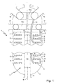
- an isothermal reactor according to the present invention for carrying out exothermic or endothermic heterogeneous reactions is indicated in its whole with 1.
- the reactor 1 comprises an outer shell 2 of substantially cylindrical shape, inside which a catalytic bed is housed, generally indicated with 3.
- the catalytic bed 3 is delimited on its sides by opposed perforated side walls 4 and 5, for the inlet of a flow comprising reactants and for the outlet of a flow comprising reacted substances, respectively.
- the substances which are fed to the reactor 1 for carrying out the exothermic or endothermic heterogeneous synthesises are in gaseous phase.
- flow comprising reactants and “flow comprising reacted substances”, it is intended to mean a flow of gaseous reactants and a flow of reacted gases, respectively. It is anyway clear that the reactor according to the present invention might be employed also for reactions occurring in liquid phase or liquid/gaseous phase, respectively.
- the perforated walls 4 and 5 are hence gas permeable with respect to the inlet in the catalytic bed 3 of a flow of gaseous reactants and to the outlet of a flow of reacted gases, respectively.
- the catalytic bed 3 is further delimited in its lower part by an unperforated bottom (not permeable to gases), that corresponds in the example of figure 1 with the bottom 6 of the reactor 1, and in its upper part by a perforated wall 7 (gas permeable) for the passage with axial motion through the bed 3 of a minor portion of the gaseous reactants.
- the side wall 5 has a small unperforated portion 5' (not permeable to gases) that extends from an upper end thereof.
- the wall 7 permeable to gases is anyway totally optional, featuring mainly the function of holding the catalyst (not represented in figure 1) inside the bed 3, so that it may be well left apart.
- a wall 7 is provided, which is not perforated or anyway not permeable to the gas.
- Both the catalytic bed of the radial type and, even in a more remarkable way, that of the axial-radial type are particularly advantageous as they allow to obtain high conversion yields and at the same time low pressure drops for the gaseous reactants, by making use of more active catalysts of smaller granulometry.
- annular space 8 for allowing an optimum distribution and feed of the gaseous reactants in the catalytic bed 3.
- the space 8 is in fluid communication with a gas inlet nozzle 9.
- the side wall 5 defines inside it a duct 10 for the collection and ejection from the reactor of the flow of reacted gases.
- the duct 10 is in fluid communication with a gas outlet nozzle 11 and is closed on its upper side by a baffle 12 not permeable to gases.
- the bed 3 is crossed by a plurality of tubes, which are all indicated by numeral 13, for the passage of a cooling or heating fluid, respectively.
- the cooling or heating fluid is fed to the tube 13 through a duct 14 in fluid communication with one or more inlet nozzles 15, and extracted from the tubes 13 through a duct 16 in fluid communication with one or more outlet nozzles 17.
- the number of nozzles 15 and 17, respectively (equal to two as far as the instant example is concerned) is chosen according to the cooling or heating fluid flow rate. Preferably, the more relevant such flow rate, the larger the number of outlet nozzles 15 and 17.
- the duct(s) 14 are in fluid communication with the nozzle(s) (15) through a toroidal collector 14a, whereas the duct(s) 16 are in fluid communication with the nozzle(s) 17 through a toroidal collector 16a.
- the tubes 13 for drawing off or supplying heat extend as a coil within the catalytic bed 3 along a plane substantially perpendicular with respect to the side walls 4 and 5 thereof.
- coil tube it is intended to mean a tube which is substantially curvilinear or provided alternatively with curvilinear and straight sections.
- each tube 13 is crossed for all its length by a same portion of reactant gases, thus being able to follow all the thermal variations, and hence the temperature profile, of such gas portion from the inlet to the outlet of the catalytic bed 3.
- the shell 2 is arranged vertically and the tubes 13 extend as coils within the catalytic bed 3 along a plane that is preferably substantially horizontal.
- the tubes are perpendicular with respect to the side walls 4 and 5, as well as with respect to the longitudinal axis 18 of the shell 2 in case of a vertical reactor, whereas they are substantially parallel with respect to the crossing direction of the bed 3 by the flow of gaseous reactants.
- a reactor 1 comprising a plurality of catalytic beds 3, wherein the beds may be crossed by a variable number of tubes 13 (at least one) according to the exothermal degree of the reaction and/or the dimensions of the catalytic bed.
- reactor 1 comprising one or more catalytic beds crossed by the flow of reactants with mainly radial motion from the centre (duct 10) towards the outer periphery (space 8).
- an outer shell of the horizontal type comprising one or more catalytic beds crossed by tubes for drawing off or supplying heat, that extend as coils along planes perpendicular with respect to the gas-permeable walls for the inlet and outlet of the gaseous reactants.
- the perforated side walls of the catalytic bed(s) are parallel with respect to the longitudinal axis of the shell.
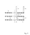
- the tubes 13 may be singularly connected to the nozzles 15 and 17, and hence each tube 13 is connected to a feed duct 14 and a duct 16 for drawing off the cooling or heating fluid, respectively. They may also be connected to groups of at least two tubes, i.e. to a duct 14 and a duct 16 for each group of tubes 13, or through a single duct 14 or 16, respectively, so that all the tubes 13 are connected to each other.
- the tubes 13 are connected to each other - at respective free ends - in groups of at least two tubes, each group being in fluid communication with a duct 14 for feeding and a duct 16 for drawing off the cooling or heating fluid, respectively.
- the various ducts 14 and 16 are, in turn, in fluid communication with the nozzle 15 and with the nozzle 17, respectively.
- connection between single adjacent tubes is accomplished by means of connecting pipes, all indicated with 19, as better shown in figures 2 and 3.
- the cooling or heating fluid is fed by means of respective ducts 14 in correspondence of one end of the lower tubes 13 of each group, is made to pass through the tubes 13 of each group, wherein heat exchanges of the same entity take place, and finally drawn off by means of respective ducts 16 from an end of the upper tubes 13 of each group.
- each single tube 13 is separately connected to the nozzles 15 and 17, particularly for long reactors which are provided with a lot of tubes 13.
- the number of ducts 14 and 16 is reduced (depending on the number of tubes 13 making up each group).
- the embodiment shown in figure 1 is more advantageous than the one wherein all the tubes 13 are connected to each other, with the tubes at the respective lower and upper ends connected to a single duct 14 and 16, respectively, as there is a lower pressure drop for the cooling or heating fluid.
- the structure with all the tubes 13 being connected to each other is particularly easy to be realised, as it needs only one feed duct 14 and one drawing off duct 16 for the cooling or heating fluid.
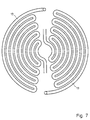
- the tube(s) 13 crossing the catalytic bed 3 for drawing off or for supplying heat are realised with a spiral-shaped coil as shown in figures 4 and 5.
- spiral shape of tubes 13 has been found to be particularly advantageous both in terms of heat exchange efficiency and in terms of simplicity and flexibility of construction.
- the spiral-shaped tube 13 may adapt itself to the most varying dimensions of the catalytic bed 3, and in particular it is able to cover all the portions of the same, thus allowing an effective heat exchange to take place everywhere in the bed.
- the spiral-shaped tube 13 may be realised with turns at a more or less close distance.
- the spiral tube is realised with a constant winding pitch, that is to say a constant distance between two adjacent turns.
- the distance between adjacent turns varies in accordance with the variation of the radius of the spiral and, preferably, the winding pitch decreases as the spiral radius increases.
- the tubes 13 may be advantageously arranged at a varying distance between the planes of two adjacent tubes.
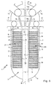
- FIG 6 an isothermal reactor is shown, for carrying out exothermic or endothermic heterogeneous reactions according to a further embodiment of the present invention.
- reactor 1 which are equivalent to those illustrated in figure 1 from the structure and operation point of view, will be indicated with the same reference numerals and will not be described any more.
- each series 20 and 21 are advantageously connected to each other by means of connecting pipes 19, so as to form two parallel series of tubes 13, generally indicated with 20 and 21. Further on, each series 20, 21 is connected by means of respective lower and upper tubes 13 to only one feed duct 14 and drawing off duct 16 for the cooling or heating fluid, respectively.
- the tubes 13 extend as a coil having the shape of an arc of a circle of increasing length from a central zone to a peripheral zone.
- the tubes 13 of each series 20, 21 may be of course arranged divided in groups inside the reactor of figure 6, such as in the example of figure 1.
- each single tube 13 extended along the entire section of the catalytic bed 3, while now the tubes 13, which are arranged side-by-side, would respectively take up a circular sector (half section).
- This tubes arrangement may be well suited for extremely exothermic or endothermic reactions as it allows to have two feeds and extractions for the cooling or heating fluid, thus increasing the heat exchange efficiency.
- the reactor according to the present invention may be advantageously employed for carrying out essentially all kinds of exothermic or endothermic reactions.
- exothermic reactions that are well suited for being carried out with the present invention may be: methanol, ammonia, formaldehyde, organic oxidation (for example ethylene oxide), whereas, examples of endothermic reactions may be: styrene and methylbenzene.
- Fluids such as hot water, that transforms into steam at a high thermal level, or melted salts or diathermal oils are preferably used for drawing off the heat (in case of exothermic reactions).
- Analogous fluids may also be used for supplying heat in case of endothermic reactions.
- synthesis pressure 50-100 bar synthesis temperature 200-300 °C
- pressure of the steam generated 15-40 bar are given: synthesis pressure 50-100 bar, synthesis temperature 200-300 °C, pressure of the steam generated 15-40 bar.
- a flow of gaseous reactants is fed to the catalytic bed 3 through the gas inlet nozzle 9 and flows inside it through the perforated walls 4 and 7.
- the catalytic bed 3 is then crossed with a mainly radial (axial-radial) motion by the gaseous reactants that react when they enter in contact with the catalyst.
- the heat developed during the synthesis reaction or required for carrying out such reaction is respectively drawn off or supplied by a fluid passing through the tubes 13.
- Such fluid is introduced into the reactor 1 through the nozzle 15 and fed to the lower tubes 13 of each group through the ducts 14. Then it passes through the tubes 13 of each respective group that are connected in correspondence of their free ends by connecting pipes 19, it is drawn off from the upper tubes 13 of the respective groups through the ducts 16 and evacuated from reactor 1 through the gas outlet duct 1.
- the operation of the reactor 1 of figure 6 is analogous to that of figure 1, with the exception that the cooling fluid contemporaneously flows through two series 20 and 21 of tubes 13 arranged side-by-side. Further on, as the tubes 13 of each series are all connected to each other, the cooling fluid is fed through a duct 14 in correspondence of a lower tube 13 and goes up through all the catalytic bed 3 passing through the tubes 13 before going out from the upper tube 13 in order to be drawn off from the reactor 1 through the nozzle 17.
- the tubes 13 extend within the catalytic bed 3 along a plane substantially parallel with respect to the crossing direction of the catalytic bed by the flow of gaseous reactants.
Priority Applications (19)
| Application Number | Priority Date | Filing Date | Title |
|---|---|---|---|
| EP99111538A EP1060788A1 (fr) | 1999-06-15 | 1999-06-15 | Réacteur catalytique isotherme pour effectuer des réactions exothermes ou endothermes hétérogènes |
| AU44236/00A AU773146B2 (en) | 1999-06-15 | 2000-05-12 | Reactor, in particular for exothermic reactions |
| CNB008089469A CN1152738C (zh) | 1999-06-15 | 2000-05-12 | 反应器、特别是放热反应的反应器 |
| DE60021747T DE60021747T2 (de) | 1999-06-15 | 2000-05-12 | Reaktor, insbesondere für exotherme reaktionen |
| DK00925516T DK1225975T3 (da) | 1999-06-15 | 2000-05-12 | Reakor, særligt til eksoterme reaktioner |
| PCT/IB2000/000636 WO2000076653A1 (fr) | 1999-06-15 | 2000-05-12 | Réacteur, en particulier pour des réactions exothermiques |
| JP2001502971A JP4630511B2 (ja) | 1999-06-15 | 2000-05-12 | 発熱反応に好適な反応器 |
| US10/009,773 US6926873B1 (en) | 1999-06-15 | 2000-05-12 | Reactor in particular for exothermic reactions |
| EP00925516A EP1225975B1 (fr) | 1999-06-15 | 2000-05-12 | R acteur, en particulier pour des r actions exothermiques |
| ARP000102940A AR024358A1 (es) | 1999-06-15 | 2000-06-14 | Reactor isotermico para reacciones en fase heterogenea exotermicas o endotermicas |
| CN00808947.7A CN1234450C (zh) | 1999-06-15 | 2000-06-14 | 用于放热或吸热非均相反应的等温反应器 |
| PCT/EP2000/005470 WO2000076652A1 (fr) | 1999-06-15 | 2000-06-14 | Reacteur isothermique permettant des reactions heterogenes exothermiques ou endothermiques |
| DK00938789T DK1194222T3 (da) | 1999-06-15 | 2000-06-14 | Isoterm reaktor til exoterme eller endoterme heterogene reaktioner |
| US10/009,783 US6958135B1 (en) | 1999-06-15 | 2000-06-14 | Isothermal reactor for exothermic or endothermic heterogeneous reactions |
| EP00938789A EP1194222B1 (fr) | 1999-06-15 | 2000-06-14 | Reacteur isothermique permettant des reactions heterogenes exothermiques ou endothermiques |
| DE60017907T DE60017907T2 (de) | 1999-06-15 | 2000-06-14 | Isothermer reaktor für exotherme oder endotherme heterogene reaktionen |
| JP2001502970A JP4651889B2 (ja) | 1999-06-15 | 2000-06-14 | 発熱または吸熱不均一反応のための等温反応器 |
| ARP000102939A AR024357A1 (es) | 1999-06-15 | 2000-06-14 | Un reactor, en particular para reacciones exotermicas y una unidad modular |
| AU54049/00A AU773016B2 (en) | 1999-06-15 | 2000-06-14 | Isothermal reactor for exothermic or endothermic heterogeneous reactions |
Applications Claiming Priority (1)
| Application Number | Priority Date | Filing Date | Title |
|---|---|---|---|
| EP99111538A EP1060788A1 (fr) | 1999-06-15 | 1999-06-15 | Réacteur catalytique isotherme pour effectuer des réactions exothermes ou endothermes hétérogènes |
Publications (1)
| Publication Number | Publication Date |
|---|---|
| EP1060788A1 true EP1060788A1 (fr) | 2000-12-20 |
Family
ID=8238355
Family Applications (3)
| Application Number | Title | Priority Date | Filing Date |
|---|---|---|---|
| EP99111538A Withdrawn EP1060788A1 (fr) | 1999-06-15 | 1999-06-15 | Réacteur catalytique isotherme pour effectuer des réactions exothermes ou endothermes hétérogènes |
| EP00925516A Expired - Lifetime EP1225975B1 (fr) | 1999-06-15 | 2000-05-12 | R acteur, en particulier pour des r actions exothermiques |
| EP00938789A Expired - Lifetime EP1194222B1 (fr) | 1999-06-15 | 2000-06-14 | Reacteur isothermique permettant des reactions heterogenes exothermiques ou endothermiques |
Family Applications After (2)
| Application Number | Title | Priority Date | Filing Date |
|---|---|---|---|
| EP00925516A Expired - Lifetime EP1225975B1 (fr) | 1999-06-15 | 2000-05-12 | R acteur, en particulier pour des r actions exothermiques |
| EP00938789A Expired - Lifetime EP1194222B1 (fr) | 1999-06-15 | 2000-06-14 | Reacteur isothermique permettant des reactions heterogenes exothermiques ou endothermiques |
Country Status (9)
| Country | Link |
|---|---|
| US (2) | US6926873B1 (fr) |
| EP (3) | EP1060788A1 (fr) |
| JP (2) | JP4630511B2 (fr) |
| CN (2) | CN1152738C (fr) |
| AR (2) | AR024358A1 (fr) |
| AU (2) | AU773146B2 (fr) |
| DE (2) | DE60021747T2 (fr) |
| DK (2) | DK1225975T3 (fr) |
| WO (2) | WO2000076653A1 (fr) |
Cited By (7)
| Publication number | Priority date | Publication date | Assignee | Title |
|---|---|---|---|---|
| WO2004101135A1 (fr) * | 2003-05-16 | 2004-11-25 | Methanol Casale S.A. | Reacteur chimique |
| WO2006045551A2 (fr) * | 2004-10-26 | 2006-05-04 | Rohr Alex | Accumulateur d'energie, systeme d'echange de chaleur d'un accumulateur d'energie, systeme d'accumulation d'energie et procede correspondants |
| US7144923B2 (en) | 2003-01-21 | 2006-12-05 | Johnson Matthey Plc | Methanol synthesis |
| WO2009019045A1 (fr) * | 2007-08-07 | 2009-02-12 | I.C.I. Caldaie S.P.A. | Réacteur chimique |
| US7727482B2 (en) * | 2003-02-17 | 2010-06-01 | Methanol Casale S.A. | Method for carrying out chemical reactions in pseudo-isothermal conditions |
| US7786180B2 (en) | 2005-05-27 | 2010-08-31 | Johnson Matthey Plc | Methanol synthesis |
| EP2320184A1 (fr) * | 2008-07-10 | 2011-05-11 | Ulvac, Inc. | Dispositif et procédé de lyophilisation |
Families Citing this family (59)
| Publication number | Priority date | Publication date | Assignee | Title |
|---|---|---|---|---|
| EP1376040A1 (fr) * | 2002-06-28 | 2004-01-02 | Methanol Casale S.A. | Unité d'échange de chaleur multiservice |
| US7232848B2 (en) | 2002-09-09 | 2007-06-19 | Conocophillips Company | Gas agitated multiphase reactor with stationary catalyst solid phase |
| US7082573B2 (en) * | 2003-07-30 | 2006-07-25 | America Online, Inc. | Method and system for managing digital assets |
| MY140160A (en) * | 2004-01-28 | 2009-11-30 | Shell Int Research | Heat exchanger for carrying out an exothermic reaction |
| EP1563900A1 (fr) * | 2004-02-12 | 2005-08-17 | Methanol Casale S.A. | Réaction chimique sous des conditions pseudo-isothermiques pour des réactions chimiques en phase hétérogène |
| US20060260789A1 (en) * | 2005-05-18 | 2006-11-23 | Yasuaki Nakagawa | Heat exchange unit and heat exchanger using the heat exchange unit |
| US7906598B2 (en) * | 2006-08-30 | 2011-03-15 | Intertape Polymer Corp. | Recirculation loop reactor bulk polymerization process |
| US20100105847A1 (en) | 2006-01-24 | 2010-04-29 | Intertape Polymer Corp. | Plug flow bulk polymerization of vinyl monomers |
| EP2057197B1 (fr) * | 2006-08-30 | 2011-07-20 | Intertape Polymer Corp. | Procédé de polymérisation en masse dans un réacteur à boucle de recirculation |
| CN100425933C (zh) * | 2006-10-23 | 2008-10-15 | 杨文� | 转化分流式热交换器 |
| US20080237090A1 (en) * | 2007-03-30 | 2008-10-02 | Nicholas Musich | Process and system for redcuing the olefin content of a hydrocarbon feed gas and production of a hydrogen-enriched gas therefrom |
| KR20110086037A (ko) * | 2008-10-13 | 2011-07-27 | 다우 글로벌 테크놀로지스 엘엘씨 | 염화된 및/또는 불화된 프로펜의 제조 방법 |
| WO2010075467A1 (fr) * | 2008-12-23 | 2010-07-01 | Mks Instruments, Inc. | Système de confinement de produit chimique réactif |
| EP2485832B1 (fr) | 2009-10-09 | 2016-11-23 | Blue Cube IP LLC | Procédé de production de propène chloré et/ou fluoré dans un réacteur multitubulaire isotherme |
| US8581012B2 (en) * | 2009-10-09 | 2013-11-12 | Dow Global Technologies, Llc | Processes for the production of chlorinated and/or fluorinated propenes and higher alkenes |
| KR20120093202A (ko) * | 2009-10-09 | 2012-08-22 | 다우 글로벌 테크놀로지스 엘엘씨 | 단열식 플러그 흐름 반응기 및 염화 및/또는 불화 프로펜 및 고급 알켄의 제조 방법 |
| JP5706432B2 (ja) * | 2009-10-09 | 2015-04-22 | ダウ グローバル テクノロジーズ エルエルシー | 塩素化及び/又はフッ素化プロペンの製造方法 |
| DE102011014639B4 (de) * | 2010-03-26 | 2018-04-05 | Jürgen Falkenstein | Erdgebundene Wärmespeicher-Vorrichtung |
| EA015285B1 (ru) * | 2010-11-26 | 2011-06-30 | Закрытое Акционерное Общество "Карбоника-Ф" | Реактор для переработки твердого топлива |
| RU2010148300A (ru) * | 2010-11-26 | 2012-06-10 | Закрытое Акционерное Общество "Карбоника-Ф" (Ru) | Реактор для переработки твердого топлива |
| US9328974B2 (en) * | 2011-02-21 | 2016-05-03 | Kellogg Brown & Root Llc | Particulate cooler |
| US8946495B2 (en) * | 2011-05-22 | 2015-02-03 | Fina Technology, Inc. | Process for alkylation of toluene to form styrene and ethylbenzene |
| US9056808B2 (en) | 2011-05-31 | 2015-06-16 | Dow Global Technologies, Llc | Process for the production of chlorinated propenes |
| CA2836493A1 (fr) | 2011-05-31 | 2012-12-06 | Max Markus Tirtowidjojo | Procede pour la production de propenes chlores |
| BR112013031230A2 (pt) | 2011-06-08 | 2017-01-31 | Dow Agrosciences Llc | processo para produção de propenos clorados e/ou fluorados |
| US8907148B2 (en) | 2011-08-07 | 2014-12-09 | Dow Global Technologies Llc | Process for the production of chlorinated propenes |
| EP2739595B1 (fr) | 2011-08-07 | 2018-12-12 | Blue Cube IP LLC | Procédé de production de propènes chlorés |
| CA2856271A1 (fr) | 2011-11-21 | 2013-05-30 | Dow Global Technologies Llc | Procede de production d'alcanes chlores |
| CN104024186B (zh) | 2011-12-02 | 2016-10-12 | 蓝立方知识产权有限责任公司 | 生产氯化烷烃的方法 |
| WO2013082410A1 (fr) | 2011-12-02 | 2013-06-06 | Dow Global Technologies, Llc | Procédé de production d'alcanes chlorés |
| US9334205B2 (en) | 2011-12-13 | 2016-05-10 | Blue Cube Ip Llc | Process for the production of chlorinated propanes and propenes |
| JP2015503523A (ja) | 2011-12-22 | 2015-02-02 | ダウ グローバル テクノロジーズ エルエルシー | テトラクロロメタンの製造方法 |
| EP2794521B1 (fr) | 2011-12-23 | 2016-09-21 | Dow Global Technologies LLC | Procédé de production d'alcènes et/ou de composés aromatiques |
| US9321707B2 (en) | 2012-09-20 | 2016-04-26 | Blue Cube Ip Llc | Process for the production of chlorinated propenes |
| JP2015529247A (ja) | 2012-09-20 | 2015-10-05 | ダウ グローバル テクノロジーズ エルエルシー | 塩素化プロペンの生成のためのプロセス |
| WO2014052945A2 (fr) | 2012-09-30 | 2014-04-03 | Dow Global Technologies, Llc | Bac à déversoir et procédés incorporant celui-ci |
| WO2014066083A1 (fr) | 2012-10-26 | 2014-05-01 | Dow Global Technologies, Llc | Mélangeur et réacteur et procédé faisant appel à eux |
| CN103044195B (zh) * | 2012-11-30 | 2015-10-21 | 河南心连心化肥有限公司 | 低压甲醇的合成方法 |
| CN104870411B (zh) | 2012-12-18 | 2018-10-02 | 蓝立方知识产权有限责任公司 | 用于生产氯化丙烯的方法 |
| CN104918904B (zh) | 2012-12-19 | 2017-10-31 | 蓝立方知识产权有限责任公司 | 用于生产氯化丙烯的方法 |
| EP2961722A2 (fr) | 2013-02-27 | 2016-01-06 | Blue Cube IP LLC | Procédé pour la production de propènes chlorés |
| CA2903760C (fr) | 2013-03-09 | 2018-02-20 | Blue Cube Ip Llc | Procede pour la production d'alcanes chlores |
| CN103752224B (zh) * | 2014-01-02 | 2015-05-20 | 衢州昀睿工业设计有限公司 | 具有螺旋预热通道的合成反应器 |
| CN105642197A (zh) * | 2014-09-24 | 2016-06-08 | 楼韧 | 一种大型反应器及其装置和工艺 |
| RU2017118397A (ru) | 2014-10-30 | 2018-11-30 | Сабик Глобал Текнолоджиз Б.В. | Реактор, содержащий расположенные в радиальном направлении охлаждающие пластины, и способы его применения |
| CN106922132A (zh) | 2014-10-31 | 2017-07-04 | 赛贝克环球科技公司 | 用于使反应的蜡产物与轻质气体产物分离的反应器 |
| US9958211B2 (en) | 2015-03-12 | 2018-05-01 | Bayotech, Inc. | Nested-flow heat exchangers and chemical reactors |
| CN105964201B (zh) * | 2016-07-12 | 2018-06-29 | 浙江金氟隆化工装备有限公司 | 一种基于滚塑四氟工艺的钢衬f40反应釜 |
| US11193716B2 (en) * | 2017-07-28 | 2021-12-07 | Fluid Handling Llc | Fluid routing methods for a spiral heat exchanger with lattice cross section made via additive manufacturing |
| DE102018007737A1 (de) * | 2018-10-01 | 2020-04-02 | Hitachi Zosen Inova Etogas Gmbh | Festbettanordnung |
| US11920873B2 (en) * | 2018-10-09 | 2024-03-05 | Linde Gmbh | Wound heat exchanger, method for producing a wound heat exchanger and method for exchanging heat between a first fluid and a second fluid |
| CN109289713B (zh) * | 2018-10-18 | 2021-04-20 | 辽宁石油化工大学 | 一种蚊香盘管等温反应器及使用方法 |
| CN109539555A (zh) * | 2019-01-16 | 2019-03-29 | 佛山市无火发热新能源科技有限公司 | 甲醇催化加热设备及加热方法 |
| CN109539556A (zh) * | 2019-01-16 | 2019-03-29 | 佛山市无火发热新能源科技有限公司 | 甲醇催化加热装置及加热方法 |
| WO2021149013A1 (fr) | 2020-01-24 | 2021-07-29 | Cri Hf | Système de réacteur de suivi de charge, installations associées, et procédé de fonctionnement de celui-ci |
| WO2022153214A1 (fr) * | 2021-01-15 | 2022-07-21 | Cri, Ehf | Réacteur de synthèse du méthanol |
| BR112023026211A2 (pt) | 2021-06-17 | 2024-03-05 | Exxonmobil Chemical Patents Inc | Processos para desidrogenação de hidrocarbonetos alcanos e alquil aromáticos |
| JP2023022850A (ja) * | 2021-08-04 | 2023-02-16 | 東洋エンジニアリング株式会社 | 反応器及びそれを用いたアンモニア分解混合物の製造方法 |
| CN114247386B (zh) * | 2021-11-24 | 2023-10-13 | 中国五环工程有限公司 | 一种蒸发式等温加氢反应方法及蒸发式等温反应系统 |
Citations (7)
| Publication number | Priority date | Publication date | Assignee | Title |
|---|---|---|---|---|
| GB391444A (en) * | 1931-10-26 | 1933-04-26 | British Celanese | Improvements in or relating to the manufacture of acetaldehyde |
| DE855258C (de) * | 1949-05-02 | 1952-11-10 | Ici Ltd | Verfahren und Apparatur zur Durchfuehrung chemischer Reaktionen |
| US3663179A (en) * | 1970-04-20 | 1972-05-16 | Chemical Construction Corp | Apparatus for exothermic catalytic reactions |
| AT362397B (de) * | 1976-10-13 | 1981-05-11 | Schober Robert Dipl Ing Dr Tec | Vorrichtung zur erhoehung des ammoniakaufbaues bei der katalytischen ammoniaksynthese |
| DE3708957A1 (de) * | 1987-03-19 | 1988-10-06 | Linde Ag | Reaktor zur katalytischen umsetzung von in einem gasstrom enthaltenem h(pfeil abwaerts)2(pfeil abwaerts)s und so(pfeil abwaerts)2(pfeil abwaerts) zu elementarem schwefel |
| EP0534195A1 (fr) * | 1991-09-21 | 1993-03-31 | BASF Aktiengesellschaft | Réacteur et procédé pour l'exécution des réactions à la catalyse hétérogène |
| WO1994012274A1 (fr) * | 1992-11-20 | 1994-06-09 | Shell Internationale Research Maatschappij B.V. | Reacteur et procede de realisation de reactions fortement exothermiques ou endothermiques |
Family Cites Families (11)
| Publication number | Priority date | Publication date | Assignee | Title |
|---|---|---|---|---|
| US2248993A (en) * | 1936-05-08 | 1941-07-15 | Houdry Process Corp | Apparatus for controlling chemical reactions |
| FR841683A (fr) * | 1937-08-05 | 1939-05-24 | Cie Francaise Procedes Houdry | Moyens pour le traitement, en phase vapeur, d'hydrocarbures, et autres applications analogues |
| CA878266A (en) * | 1969-04-21 | 1971-08-17 | Brants Henry | Heat exchanger |
| DE3007202A1 (de) * | 1980-02-26 | 1981-09-10 | Linde Ag, 6200 Wiesbaden | Methanol-reaktor |
| DE3217066A1 (de) | 1982-05-06 | 1983-11-10 | Linde Ag, 6200 Wiesbaden | Reaktor zur durchfuehrung katalytischer reaktion |
| JPS59162942A (ja) * | 1983-03-07 | 1984-09-13 | Toyo Eng Corp | 反応器 |
| DE3318098A1 (de) | 1983-05-18 | 1984-11-22 | Linde Ag, 6200 Wiesbaden | Verfahren und reaktor zur durchfuehrung einer endo- oder exothermen reaktion |
| JPS60150824A (ja) * | 1984-01-18 | 1985-08-08 | Toyo Eng Corp | 改良反応器 |
| US5080872A (en) * | 1985-09-26 | 1992-01-14 | Amoco Corporation | Temperature regulating reactor apparatus and method |
| GB2204055B (en) * | 1987-04-29 | 1992-01-02 | Shell Int Research | Process for the preparation of hydrocarbons |
| IT1319549B1 (it) * | 2000-12-14 | 2003-10-20 | Methanol Casale Sa | Reattore per l'effettuazione di reazioni eterogenee esotermiche oendotermiche |
-
1999
- 1999-06-15 EP EP99111538A patent/EP1060788A1/fr not_active Withdrawn
-
2000
- 2000-05-12 DK DK00925516T patent/DK1225975T3/da active
- 2000-05-12 AU AU44236/00A patent/AU773146B2/en not_active Expired
- 2000-05-12 CN CNB008089469A patent/CN1152738C/zh not_active Expired - Lifetime
- 2000-05-12 DE DE60021747T patent/DE60021747T2/de not_active Expired - Lifetime
- 2000-05-12 US US10/009,773 patent/US6926873B1/en not_active Expired - Lifetime
- 2000-05-12 WO PCT/IB2000/000636 patent/WO2000076653A1/fr active Search and Examination
- 2000-05-12 JP JP2001502971A patent/JP4630511B2/ja not_active Expired - Lifetime
- 2000-05-12 EP EP00925516A patent/EP1225975B1/fr not_active Expired - Lifetime
- 2000-06-14 WO PCT/EP2000/005470 patent/WO2000076652A1/fr active IP Right Grant
- 2000-06-14 DE DE60017907T patent/DE60017907T2/de not_active Expired - Lifetime
- 2000-06-14 AR ARP000102940A patent/AR024358A1/es unknown
- 2000-06-14 CN CN00808947.7A patent/CN1234450C/zh not_active Expired - Lifetime
- 2000-06-14 DK DK00938789T patent/DK1194222T3/da active
- 2000-06-14 US US10/009,783 patent/US6958135B1/en not_active Expired - Lifetime
- 2000-06-14 JP JP2001502970A patent/JP4651889B2/ja not_active Expired - Lifetime
- 2000-06-14 AR ARP000102939A patent/AR024357A1/es unknown
- 2000-06-14 EP EP00938789A patent/EP1194222B1/fr not_active Expired - Lifetime
- 2000-06-14 AU AU54049/00A patent/AU773016B2/en not_active Expired
Patent Citations (7)
| Publication number | Priority date | Publication date | Assignee | Title |
|---|---|---|---|---|
| GB391444A (en) * | 1931-10-26 | 1933-04-26 | British Celanese | Improvements in or relating to the manufacture of acetaldehyde |
| DE855258C (de) * | 1949-05-02 | 1952-11-10 | Ici Ltd | Verfahren und Apparatur zur Durchfuehrung chemischer Reaktionen |
| US3663179A (en) * | 1970-04-20 | 1972-05-16 | Chemical Construction Corp | Apparatus for exothermic catalytic reactions |
| AT362397B (de) * | 1976-10-13 | 1981-05-11 | Schober Robert Dipl Ing Dr Tec | Vorrichtung zur erhoehung des ammoniakaufbaues bei der katalytischen ammoniaksynthese |
| DE3708957A1 (de) * | 1987-03-19 | 1988-10-06 | Linde Ag | Reaktor zur katalytischen umsetzung von in einem gasstrom enthaltenem h(pfeil abwaerts)2(pfeil abwaerts)s und so(pfeil abwaerts)2(pfeil abwaerts) zu elementarem schwefel |
| EP0534195A1 (fr) * | 1991-09-21 | 1993-03-31 | BASF Aktiengesellschaft | Réacteur et procédé pour l'exécution des réactions à la catalyse hétérogène |
| WO1994012274A1 (fr) * | 1992-11-20 | 1994-06-09 | Shell Internationale Research Maatschappij B.V. | Reacteur et procede de realisation de reactions fortement exothermiques ou endothermiques |
Non-Patent Citations (1)
| Title |
|---|
| ULRICH LAHNE & REINER LOHMÜLLER: "Schüttschichtreaktoren mit gewickelten Kühlrohren, eine konstruktive Neuentwicklung zur Durchführung exothermer katalytischer Prozesse", CHEMIE. INGENIEUR. TECHNIK., vol. 58, no. 3, 1986, VERLAG CHEMIE GMBH. WEINHEIM., DE, pages 212 - 215, XP002124824, ISSN: 0009-286X * |
Cited By (11)
| Publication number | Priority date | Publication date | Assignee | Title |
|---|---|---|---|---|
| US7144923B2 (en) | 2003-01-21 | 2006-12-05 | Johnson Matthey Plc | Methanol synthesis |
| US7727482B2 (en) * | 2003-02-17 | 2010-06-01 | Methanol Casale S.A. | Method for carrying out chemical reactions in pseudo-isothermal conditions |
| WO2004101135A1 (fr) * | 2003-05-16 | 2004-11-25 | Methanol Casale S.A. | Reacteur chimique |
| US7807115B2 (en) | 2003-05-16 | 2010-10-05 | Methanol Casale S.A. | Chemical reactor |
| US8071059B2 (en) | 2003-05-16 | 2011-12-06 | Methanol Casale S.A. | Chemical reactor |
| WO2006045551A2 (fr) * | 2004-10-26 | 2006-05-04 | Rohr Alex | Accumulateur d'energie, systeme d'echange de chaleur d'un accumulateur d'energie, systeme d'accumulation d'energie et procede correspondants |
| WO2006045551A3 (fr) * | 2004-10-26 | 2006-08-17 | Rohr Alex Von | Accumulateur d'energie, systeme d'echange de chaleur d'un accumulateur d'energie, systeme d'accumulation d'energie et procede correspondants |
| US7786180B2 (en) | 2005-05-27 | 2010-08-31 | Johnson Matthey Plc | Methanol synthesis |
| WO2009019045A1 (fr) * | 2007-08-07 | 2009-02-12 | I.C.I. Caldaie S.P.A. | Réacteur chimique |
| EP2320184A1 (fr) * | 2008-07-10 | 2011-05-11 | Ulvac, Inc. | Dispositif et procédé de lyophilisation |
| EP2320184A4 (fr) * | 2008-07-10 | 2014-06-25 | Ulvac Inc | Dispositif et procédé de lyophilisation |
Also Published As
| Publication number | Publication date |
|---|---|
| US6926873B1 (en) | 2005-08-09 |
| AR024358A1 (es) | 2002-10-02 |
| CN1355725A (zh) | 2002-06-26 |
| AU773016B2 (en) | 2004-05-13 |
| AR024357A1 (es) | 2002-10-02 |
| DK1194222T3 (da) | 2005-06-13 |
| CN1355724A (zh) | 2002-06-26 |
| JP4630511B2 (ja) | 2011-02-09 |
| CN1234450C (zh) | 2006-01-04 |
| EP1194222A1 (fr) | 2002-04-10 |
| JP4651889B2 (ja) | 2011-03-16 |
| EP1225975A1 (fr) | 2002-07-31 |
| WO2000076653A1 (fr) | 2000-12-21 |
| AU773146B2 (en) | 2004-05-20 |
| DE60021747T2 (de) | 2006-06-01 |
| JP2003501253A (ja) | 2003-01-14 |
| DK1225975T3 (da) | 2005-12-05 |
| EP1225975B1 (fr) | 2005-08-03 |
| DE60021747D1 (de) | 2005-09-08 |
| WO2000076652A1 (fr) | 2000-12-21 |
| US6958135B1 (en) | 2005-10-25 |
| CN1152738C (zh) | 2004-06-09 |
| AU4423600A (en) | 2001-01-02 |
| DE60017907D1 (en) | 2005-03-10 |
| EP1194222B1 (fr) | 2005-02-02 |
| JP2003524518A (ja) | 2003-08-19 |
| AU5404900A (en) | 2001-01-02 |
| DE60017907T2 (de) | 2006-03-30 |
Similar Documents
| Publication | Publication Date | Title |
|---|---|---|
| EP1194222B1 (fr) | Reacteur isothermique permettant des reactions heterogenes exothermiques ou endothermiques | |
| EP1216750B1 (fr) | Reacteur pour effectuer des réactions exothermiques ou endothermiques heterogènes | |
| CA2407907C (fr) | Reacteur utilise pour des reactions heterogenes exothermiques ou endothermiques | |
| US4594227A (en) | Reaction method and reactor therefor | |
| EP2066435B1 (fr) | Réacteur isotherme | |
| US6955792B2 (en) | Pseudo isothermal catalytic reactor for exothermic or endothermic heterogeneous chemical reactions | |
| US8071059B2 (en) | Chemical reactor | |
| AU2002347040A1 (en) | Heat exchange unit for isothermal chemical reactors | |
| EP1436075A1 (fr) | Unite d'echange thermique pour reacteurs chimiques isothermes | |
| EP2473267B1 (fr) | Réacteur isothermique à calandre vertical et son utilisation pour la synthèse de methanol | |
| CN102164662A (zh) | 用于等温化学反应器的具有径向布置的元件的热交换器 | |
| MX2007001173A (es) | Reactor catalitico de lecho fijo. | |
| AU712231B2 (en) | Process and reactor for heterogeneous exothermic synthesis of formaldehyde | |
| WO1995024961A1 (fr) | Reacteur horizontal destine a la synthese exothermique heterogene, notamment a la synthese du methanol |
Legal Events
| Date | Code | Title | Description |
|---|---|---|---|
| PUAI | Public reference made under article 153(3) epc to a published international application that has entered the european phase |
Free format text: ORIGINAL CODE: 0009012 |
|
| AK | Designated contracting states |
Kind code of ref document: A1 Designated state(s): DE DK FR NL |
|
| AX | Request for extension of the european patent |
Free format text: AL;LT;LV;MK;RO;SI |
|
| 17P | Request for examination filed |
Effective date: 20010528 |
|
| STAA | Information on the status of an ep patent application or granted ep patent |
Free format text: STATUS: THE APPLICATION HAS BEEN WITHDRAWN |
|
| AKX | Designation fees paid |
Free format text: DE DK FR NL |
|
| AXX | Extension fees paid |
Free format text: RO PAYMENT 20010528 |
|
| 18W | Application withdrawn |
Withdrawal date: 20010626 |