EP1060619B1 - Datenübertragungssystem - Google Patents
Datenübertragungssystem Download PDFInfo
- Publication number
- EP1060619B1 EP1060619B1 EP99938030A EP99938030A EP1060619B1 EP 1060619 B1 EP1060619 B1 EP 1060619B1 EP 99938030 A EP99938030 A EP 99938030A EP 99938030 A EP99938030 A EP 99938030A EP 1060619 B1 EP1060619 B1 EP 1060619B1
- Authority
- EP
- European Patent Office
- Prior art keywords
- signal
- receiver
- receivers
- transmitter
- received
- Prior art date
- Legal status (The legal status is an assumption and is not a legal conclusion. Google has not performed a legal analysis and makes no representation as to the accuracy of the status listed.)
- Expired - Lifetime
Links
Images


Classifications
-
- H—ELECTRICITY
- H04—ELECTRIC COMMUNICATION TECHNIQUE
- H04B—TRANSMISSION
- H04B7/00—Radio transmission systems, i.e. using radiation field
- H04B7/02—Diversity systems; Multi-antenna system, i.e. transmission or reception using multiple antennas
- H04B7/04—Diversity systems; Multi-antenna system, i.e. transmission or reception using multiple antennas using two or more spaced independent antennas
- H04B7/08—Diversity systems; Multi-antenna system, i.e. transmission or reception using multiple antennas using two or more spaced independent antennas at the receiving station
- H04B7/0802—Diversity systems; Multi-antenna system, i.e. transmission or reception using multiple antennas using two or more spaced independent antennas at the receiving station using antenna selection
- H04B7/0817—Diversity systems; Multi-antenna system, i.e. transmission or reception using multiple antennas using two or more spaced independent antennas at the receiving station using antenna selection with multiple receivers and antenna path selection
- H04B7/082—Diversity systems; Multi-antenna system, i.e. transmission or reception using multiple antennas using two or more spaced independent antennas at the receiving station using antenna selection with multiple receivers and antenna path selection selecting best antenna path
-
- H—ELECTRICITY
- H04—ELECTRIC COMMUNICATION TECHNIQUE
- H04N—PICTORIAL COMMUNICATION, e.g. TELEVISION
- H04N7/00—Television systems
- H04N7/18—Closed-circuit television [CCTV] systems, i.e. systems in which the video signal is not broadcast
- H04N7/181—Closed-circuit television [CCTV] systems, i.e. systems in which the video signal is not broadcast for receiving images from a plurality of remote sources
-
- H—ELECTRICITY
- H04—ELECTRIC COMMUNICATION TECHNIQUE
- H04N—PICTORIAL COMMUNICATION, e.g. TELEVISION
- H04N7/00—Television systems
- H04N7/18—Closed-circuit television [CCTV] systems, i.e. systems in which the video signal is not broadcast
- H04N7/183—Closed-circuit television [CCTV] systems, i.e. systems in which the video signal is not broadcast for receiving images from a single remote source
- H04N7/185—Closed-circuit television [CCTV] systems, i.e. systems in which the video signal is not broadcast for receiving images from a single remote source from a mobile camera, e.g. for remote control
Definitions
- This invention relates to a system for transmitting data, particularly audio and video signal data, to and from a moving object.
- the vehicle may be provided with an antenna for beaming a signal to a helicopter located above the car.
- the helicopter then relays the signal from the car to and from a fixed ground station.
- a further limitation of the use of helicopters for relaying signals is the limited amount of weight that can be carried to allow the helicopter to remain at its station for the duration of a race. Similarly, there is a limitation on the amount of power that can be provided for running the radio frequency systems.
- a system for transmitting video signals from hand-held cameras to a central point is described in GB-A-2 307 375. This system decides upon switching between receivers on the basis of measurements of the quality of the received signal.
- a communication system including:
- a method of communicating a video signal between a mobile object and a stationary location comprising:
- the present invention still further provides a method of establishing a communication system for communicating a video signal between a mobile object provided with a transmitter for transmitting the video signal on a first carrier frequency and a stationary location comprising providing a plurality of receivers each having a detection area within which the receiver is able to receive the signal from the transmitter on said first carrier frequency when the transmitter is in the detection area, the method comprising the steps of:
- the present invention is arranged so that switching between receivers is carried out on the basis of the position of the mobile object.
- the receivers are preferably arranged so that the area in which they can receive signals at an acceptable level overlaps with the receiver in the corresponding adjacent area.
- the transmitters on the mobile object may be arranged to be able to transmit on a number of different frequencies.
- the receivers may also be adapted to receive on a number of different frequencies.
- the operating frequencies of the transmitters and the receivers are preferably controlled by data messages sent from a central location to the moving objects and receiver stations.
- Each frequency may be received by a dedicated antenna (i.e. each receiver having its own antenna) or a single antenna and an RF splitter may be used with a proportion of the RF signal being directed to each receiver.
- the receiver selects the wanted frequency in the RF signal.
- the video signal is preferably transmitted from the mobile object to the receivers using a microwave carrier. This is preferably at 2.5 GHz.
- Other data and audio signals may be modulated onto the video signal or transmitted on a separate frequency, preferably between 100 MHz and 40 GHz.
- the present invention requires only a single frequency to transmit a video signal as there is no re-transmission of the signal as in the case of a helicopter-based system. This allows a doubling in the number of signals that can be transmitted for a given number of frequencies. Furthermore, because the transmission from each transmitter is received by a receiver at relatively close range, the transmission power can be reduced. This also allows the same frequency to be used simultaneously between another transmitter and receiver at a different location. This is not possible with helicopter based systems in which all signals have to go via one helicopter and so only one transmitter could use a given frequency in order to avoid interference.
- the receivers are preferably provided in a trackside receiver station.
- the station preferably includes an antenna and optionally additional receivers.
- Figure 1 shows an example of a section of racetrack 1 and a suitable arrangement of receiver stations 2 (referred to herein as stations) around such a section of track to provide continuous reception of a video signal from an on-board camera in a racing car.
- the embodiment of the present invention described herein relates to a system for providing communication of a video signal from a moving racing car to a fixed location such as an outside broadcast unit.
- Each station includes at least one antenna and one receiver. This is preferably a directional antenna (e.g. helix antenna) but may be an omnidirectional antenna.
- the dashed lines in Figure 1 provide an indication of the detection angle of the antenna on each station 2.
- the signal received by the antenna is fed to the receiver in the station and then fed back to a controller at a central location where the signal from one of the receivers is selected as the most appropriate.
- the selected signal is then used to provide the output signal from the system, e.g. for broadcast.
- This overlap ensures that as the car travels from the reception area of one station to the reception area of the next station, the car passes through an area where the video signal transmitted by the car is received by the antennas of both stations. At some point in this area, the system switches from using the signal from the first station to using the signal from the next station.
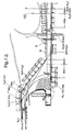
- Figure 2 shows a schematic view of a section of a track showing the antennas (A 2 , A 3 , A 4 , etc.) of a number of stations.
- the antenna A 2 is initially receiving the signal transmitted by the car.
- the car enters the reception range of the next antenna A 3 at which point the signal being output is received by A 3 as well as by A 2 .
- the signal being received by A 2 is still the one being utilised to provide the output signal.
- the system switches from using the signal from A 2 to using the signal from A 3 although the signal from the car is still being received by A 2 .
- antenna A 2 eventually becomes unable to receive the signal from the car so that only antenna A 3 is receiving the signal.
- This switching procedure is repeated as the car progresses around the track and moves from the reception area of one station to the next. As is clear from figure 2 switching takes place at a distance D 2 , D 3 or D 4 before the car reaches the antenna of the station currently providing the video signal which is being utilised. This ensures that a good quality signal is still being received up until the changeover. If the changeover was delayed until the car was level with the antenna, the signal strength received by the antenna may drop off considerably as the car drops out of the optimum reception zone of the antenna.
- the exact point at which switching takes place is very important. If switching occurs too early, e.g. at P 2 , the strength of the signal received by A, may be weak. As described above, leaving switching until too late can result in the signal received by A 2 being too weak. If the received signal is weak then the output signal may be distorted or noisy. However, to determine the appropriate switching point it is not sufficient to simply measure the strength of the signal received by each receiver and then select the strongest of those. This can lead to a misleading indication of the best signal and hence the wrong switching position. One of the reasons for this is interference caused by the transmitted signal arriving at the antenna indirectly, i.e. having reflected off some other object. This phenomenon, known as multipath, results in the direct and indirect signals having taken paths of different lengths to arrive at the receiver.
- the two signals may constructively interfere, providing a stronger signal, or destructively interfere reducing the signal strength.
- this difference between the path lengths may change and so the signal strength may vary between being very weak and being very strong. This variation makes it difficult to use the signal strength as the sole accurate indicator of which receiver to use for the output signal.
- the system of this invention determines the appropriate time to change from one receiver to the next based upon the position of the car relative to the antenna. This requires knowledge of the position of the stations and the car. This can be determined in a number of ways. On a racetrack, data may be available from the time keeping system. This allows the position of the cars to be determined accurately at any time. However, there are a number of alternative ways of determining position. Apart from well-known systems such as GPS (Global Positioning System), it would be possible to use a custom system for providing position information, for example by utilising the stations themselves to determine the distance from the car. Even where highly accurate position information is not available, it is still possible to interpolate to provide an estimated position. In a racing track situation, the cars follow fairly predictable position and speed paths, allowing accurate estimation of the car's position.
- GPS Global Positioning System
- the stations On a racetrack, which may be several kilometres long, the stations may be a long way away from each other and from the controller at the central location.
- the simplest way of delivering the signals received by the receivers to the central controller is by directly connecting, e.g. via a cable, each receiver to the controller.
- the system can enable a number of cars to provide video signals, by each car transmitting on a different frequency. Where two or more cars are in the reception area of the same station, the antenna receives both signals.
- This system can be further developed to allow for additional cameras where the number of frequencies available for transmission is limited or if there are a large number of cars in a race. Furthermore it may be desired to have more than one signal being produced from each car (e.g. forward and rearward views or a view of the driver). Under such circumstances a large number of channels may be required. If the bandwidth available is limited, it is possible to utilise the same frequency for signals provided by different cars. This is possible so long as cars transmitting on the same frequency are sufficiently far apart such that the station picking up the signal from one car does not pick up a significant amount of the signal from another car transmitting on the same frequency.
- the position information used to determine switching between stations may be used to determine the allocation of frequencies to the transmitters. In this way, several cars at different positions around the track can use the same frequency simultaneously. This represents a considerable advantage over the helicopter-based system that could only utilise a single transmitter per frequency.
- each transmitter only uses a single frequency rather than the two required with the helicopter system, i.e. one for transmitting to the helicopter and one for the relay to the ground based receiver.
- a common "bus" system to which all receivers are attached.
- this comprises two connections: an A-line and a B-line, each line being capable of carrying a video signal.
- These two lines are arranged to connect the central location and each of a number of nodes.
- the lines instead of the line going from the central location to each node, the lines connect from the central location to the first node and then from the first node to the second node and so on until the last node which is preferably connected back to the central location to form a ring.
- Each receiver may have its own node or a node may be provided for more than one receiver. For example, for a set up comprising twenty receivers, five nodes may be provided with four receivers connected directly to each node.
- Figure 5 shows an example of a node to which two receivers in two stations receiving the signals provided by antennas A 2 and A 3 , are connected.
- signals from each receiver can be connected either to the A-line, the B-line or to neither line (NC).
- a 2 which, as is shown in Figure 5, is connected to the A-line.
- the received signal is then passed back down the line from node to node until the signal is received at the central location.
- the signal transmitted to the car is then receivable by A 3 and the switch in the node connects the signal provided from the receiver for antenna 3 to the B-line.
- the received signal from A 3 is then passed from node to node down the B-line, again back to the central location.
- the central location is provided with two video signals corresponding to the signals received at antennas A 2 and A 3 .
- the central location is provided with switching means.
- the switching means outputs the video signal provided on the A- or the B-lines according to a control signal provided by a controller.
- the control signal comprises data messages sent from control software operating on a computer.
- the software selects which of the video signals on the A-line and B-line is output.
- the software controls the switch to provide an output signal from the A-line, then as the car passes point P 3 , the software sends a message to the switcher so the output corresponds to the signal being received on the B-line (i.e. that received by antenna A 3 ).
- Two synchronisers are employed to ensure the sync pulses of the video signals on the A-line and B-line are coincident.
- the switcher waits until the next vertical blanking interval of the current video signal and then switches between the A-line and the B-line, or vice versa.
- a frame memory may be employed. The use of a frame memory avoids any problems due to the frames in the two signals not being synchronised.
- the software sends a message to the switcher in the central location to switch from outputting the signal on the B-line to outputting the signal on the A-line (which corresponds to the signal received by A 4 ). This process is repeated as the car continues around the track with the A-line and B-line alternatively providing the output signal.
- the exact timing of the disconnection of one receiver e.g.
- a 2 and the connection of the next receiver to the same line is not essential as long as the signal on that line is not being utilised.
- the disconnection of A 2 from the A-line may be as soon as the signal received by A 2 is too weak or it may be delayed until the time at which the signal from A 4 is sufficiently strong.
- Figure 5 indicates that once the RF signal has been received it is converted back to a baseband video signal.
- the A-line and the B-line are therefore independent of the received frequency and hence can be used to provide transmission of video signals from more than one car.
- the A/B Line pair are only capable of transmitting the two video signals required when following a single car around the track.
- a separate pair of lines e.g. a C-line and D-line can be provided.
- the C/D-line pair are independent of frequency they can be used in the transmission of video pictures from a car transmitting on any frequency within a specified receiving band.
- the second car may be transmitting on the same frequency as the car being followed by the A/B-line pair.
- the cars are required to be at different locations around the circuit so that the RF signals reaching the receiver from the two cars do not interfere with each other.
- extra line pairs allows an increase in the system capacity by one car.
- Further pairs (E/F-line, etc.) may also be added to allow third and further cars to be followed around the track. It is however, still possible to have several cars transmitting at the same time around the track without having a second (C/D-line) system. It is however only possible to relay the signal from one of those cars at a time with the signals received by other antennas from other cars not being connected to the A or B-lines.
- the receivers may be connected to a network (e.g. LAN).
- the network may link all the receivers or just a proportion of them in conjunction with other networks.
- the central controller can instruct which receivers should send their received signals.
- the layout of the receiver stations around the track requires careful planning to provide the required coverage with the optimum number of stations. In theory it would be possible to simply place a large number of stations at regular intervals around the track to ensure that the signal transmitted by the car can be detected by at least one of them at all positions on the track. However, such a layout introduces other problems into the system. If stations are placed too close together then, apart from the unnecessary additional cost of having more stations than necessary, the complexity of the switching and controlling system is increased because the signal from a transmitter may be picked up by several antennas. Equally having too few base stations may leave areas of the track where only a poor quality or no signal can be received. Therefore, in order to achieve consistent coverage of the entirety of the track, with the minimum number of receivers, the receiver stations are laid out as follows.
- a typical helix antenna provides a detection area (or receive envelope) which is a 30° segment of a circle with a maximum range of around 200 metres.
- the receive envelope cut off area is from 30 to 60 metres depending on the height of the antenna above the ground (from 1.5 metres to 3 metres respectively).
- the 30 degree segment of a circle is described as the beamwidth of the antenna and is a specification supplied by the antenna manufacturer.
- the maximum range is determined by the maximum distance at which the received power level is sufficiently high to produce broadcast quality video signal.
- the minimum receive power level used for broadcast quality pictures is -60dB.
- the receive envelope cut off area is the distance in front of the antenna at which the video signal breaks up.
- the break up in the video picture is caused by a drop in the received power level resulting from cancelling of the direct signal by a reflection of the same signal off the ground.
- the distance at which this occurs is dependant on the height of the transmit antenna and the height of the receive antenna above the ground.
- the frequency of the RF signal will also change the location of the cut off point.
- the amount of reflection and hence its effect depends on the surface over which the wave is travelling as well as upon the wavelength of the signal. The following reflection equation can be derived:
- h r and h t are receiver and transmitter heights relative to the reflection surface and d is the distance between the receiver and transmitter.
- the reflection surface may not be the ground. For instance it may be a wall or barrier.
- the values h r and h t refer to the distance between the reflection surface and the respective antennas.
- Fresnel zones surround the direct ray path between the transmitter and receiver.
- the first Fresnel zone refers to the zone immediately surrounding the direct ray path. This zone is defined in such a way that the path length of a ray which has been deflected between the transmitter and receiver is within half a wavelength of the path length of the direct ray.
- any object, including the ground, aligning within this zone will lead to attenuation of the received signal.
- a compromise is therefore made when mounting the antennas.
- the track is surrounded by metal barriers, known as Armco, which are approximately 1 metre high or with fencing which is approximately 3 metres high.
- Antennas are mounted half a metre above the Armco so that the RF Signal is not attenuated by being located near to the metal structure or the tyre wall in-front. Therefore, because the antennas are mounted by these track features, the most common mounting heights for the antennas are 1.5 metres and 3 metres.
- the mounting requirements for each site are determined by reviewing the physical layout of the site at that point and determining limiting factors which may prevent optimum locations of each circuit or conducting an on the spot circuit review.
- the receive envelope which lies between the outer limit of the antennas range (R 4 - see Figure 6) and the inner limit (R 1 , R 2 ) determined by the point at which signal drop out occurs, can be determined. Having determined this receive envelope, it is necessary also to establish the amount of overlap with the receive envelope of the antenna of the adjacent station to ensure a smooth transition from using the signal from one station to using the signal from the next station. Thus, a range R 3 corresponding to the point at which the signal from the adjacent antenna can no longer be received is chosen defining an overlap region between R 3 and R 4 .
- the position of the first station (Rx1) is selected at the end of a long, for example, the Start/Finish straight (see Figure 7.1).
- the performance of this site is then established, the results of which enable the station previous (Rx 34) to the current station (Rx1), and the subsequent station (Rx2) to be located.
- Rx 1 is mounted at 3 metres high, therefore, using the reflection equation, the drop out point for the site will be 60 metres in front of the antenna.
- the operation of the system is based on an optimum overlap zone between the receive sites of 20 metres, this allows for fluctuation in vehicle position at the point at which the video is switched. If accurate position information is not available then the overlap zone can be increased to avoid the possibility of the signal being lost by switching from one receiver to the next too soon or too late. This 20 metres is added onto the drop out point and establishes the point on the track at which the subsequent station must be providing clean pictures (points A and B).
- a line is then projected from the subsequent station pick up point on the inside of the track (point A), in the direction the cars travel, onto the perimeter fence at the maximum possible distance around the track.
- the projected line should provide a clear line of sight from the transmitter to the receiver and should therefore not cross any defining boundary lines such as perimeter fences, buildings, trees or other structures.
- the process should be repeated to the point on the outside of the track (point B). As can be seen in Figure 7.1 the resulting site location may be different to that already determined. It should also be noted that if the receive station was located at position A on the perimeter fence then a clear line of site to pick up point B could not be achieved because of the perimeter fence on the inside of Turn 2.
- Figures 7.3 and 7.4 indicate how the reflection equation is applied in a practical environment. It can be clearly seen in both figures that the receive antenna height (relative to the reflecting plane - in this case the fence) is a constant value. In Figure 7.3 the fence under investigation (FENCE 1) is parallel to the direction of travel and hence the height of the transmitter also remains at a constant distance. For Figure 7.3 the only variable becomes the transmission distance as the transmitting vehicle moves closer to the receive station. In Figure 7.4 it can be seen that the height of the transmit antenna will change as the transmission distance changes, therefore, two variables exist. Application of the reflection equation becomes more complicated when performing calculations relating to curved fences (as for example would be required in establishing the performance of receive station RX3 in the figures). In this case the height of the receive antenna relative to the fence would also change continuously as transmission distance changes, and therefore the equation includes three variables.
- the drop out distances produced by the reflection equation calculations can be very sensitive to small changes in antenna height relative to the reflective plane. For example, if the height of the transmitter was 4 metres and the height of the receiver 5 metres the first drop out point would occur at 333 metres (assuming the transmission frequency was 2.5 GHz). If the transmitter height was increased to 4.5 metres the first drop out point would become 375 metres. From this brief calculation it can be derived that if the vehicle follows a different path around the track, then the manner in which reflections from the surroundings affect the receiver station performance could vary greatly. It also indicates the importance of accurate location information to ensure theoretical system planning is as accurate as possible.
- a further item to consider in the application of the reflection equation is the term relating to the RF signal wavelength and hence frequency. If, using the first example above, the frequency was lowered to 2.4 GHz then the first drop out point would occur at 320 metres, a difference of 13 metres. From this it can be derived that the set-up of the system would be different depending on the transmission frequency.
- Figure 7.2 shows that receiver station RX34 is connected to Node 1 (N1).
- the cable run is about 40 metres which would be relatively quick to pull out, but there is a track access point just before the site, so a trench would need to be dug and the cable buried for protection of the cable and to keep the access way clear.
- the site could not be located just before the access point because the stagger in the fence would block the antenna, therefore the receiver station could be moved back to approximately the same location as Node 1 making the cable run short and easy.
- the net result would be to increase the overlap with station RX1, but to reduce overlap with station RX33.
- all important factors must be considered as early in the planning stage as possible, and where possible flexibility for minor adjustments should be built into the planning of the system.
- the above method of sighting the receiver stations relates to stations provided with antennas having a narrow detection range (eg. 30°). However, these principles can be applied using antennas having a larger detection angle.
- Each station comprises at least one receiver.
- Each receiver may have its own dedicated antenna or the station may have a single antenna and a splitter for separating the various frequencies received and sending them to respective receivers.
- the stations also include filters and de-modulators 4, for extracting the video signal from the received microwave transmission.
- the video signal may then be sent to the central controller as a baseband signal which includes the video picture information and the audio signals modulated onto separate sub-carriers.
- the system may send the actual signal received by the antenna stations, i.e. the microwave signal, back to a central location where the receiver units and demodulator would be located. This type of system would require the RF signal to be modulated onto the fibre optic transport system, and each site would preferably have a dedicated fibre link back to the central location.
- the antennas are preferably helix antennas but these may be replaced by any other type of suitable antenna (such as fan-beam antennas, patch antennas or omnidirectional antennas depending upon their location and the layout of the track.
- suitable antenna such as fan-beam antennas, patch antennas or omnidirectional antennas depending upon their location and the layout of the track.
- an omnidirectional antenna may be used to cover a bend whilst a directional antenna is used for straighter sections.
- the directional antennas preferably have an angular range of between 30° and 120° depending on their location.
Landscapes
- Engineering & Computer Science (AREA)
- Signal Processing (AREA)
- Multimedia (AREA)
- Computer Networks & Wireless Communication (AREA)
- Mobile Radio Communication Systems (AREA)
- Communication Control (AREA)
- Radar Systems Or Details Thereof (AREA)
- Radio Relay Systems (AREA)
- Radio Transmission System (AREA)
- Closed-Circuit Television Systems (AREA)
- Optical Communication System (AREA)
- Small-Scale Networks (AREA)
- Two-Way Televisions, Distribution Of Moving Picture Or The Like (AREA)
Claims (15)
- Ein Kommunikationssystem, welches aufweist:gekennzeichnet durch:eine Videosignalquelle und einen Sender, die auf einem beweglichen bzw. mobilen Objekt vorgesehen sind, um das besagte Videosignal zu erzeugen und zu übertragen auf wenigstens einer ersten Trägerfrequenz; undwenigstens erste und zweite Empfänger (2) zum Empfangen des besagten gesendeten Videosignals auf der besagten ersten Trägerfrequenz, wobei die besagten ersten und zweiten Empfänger wenigstens teilweise überlappende Detektions- bzw. Erkennungsbereiche haben und an zueinander beabstandeten Orten angeordnet sind;einen Positionsdetektor zum Erzeugen eines Positionssignals, welches die Position des besagten beweglichen bzw. mobilen Objekts angibt, wobei andere Anzeigen bzw. Angaben als Parameter des empfangenen Videosignals und Trägers verwendet werden;einen Kontroller bzw. ein Steuergerät, welcher bzw. welches auf das besagte Positionssignal anspricht, um eines der durch die besagten ersten und zweiten Empfänger empfangenen Videosignale auszuwählen und um das ausgewählte Signal auszugeben, wobei der besagte Kontroller bzw. das besagte Steuergerät anderswo als in dem besagten beweglichen bzw. mobilen Objekt angeordnet ist.
- System gemäß Anspruch 1, bei welchem der Kontroller bzw. das Steuergerät von dem Empfangen des durch den besagten ersten Empfänger empfangenen Signals zu dem besagten zweiten Empfänger wechselt, wenn das bewegliche bzw. mobile Objekt in einer vorbestimmten Entfernung von dem besagten ersten Empfänger ist.
- System gemäß Anspruch 1 oder 2, wobei die ersten und zweiten Empfänger Wendelantennen haben.
- System gemäß Anspruch 3, wobei die Antenne in einer Höhe im Bereich von 1,3 bis 3 m in Bezug auf die Erde bzw. den Boden angeordnet ist.
- System gemäß einem der Ansprüche 1 bis 4, wobei der Sender so gesteuert werden kann, dass er selektiv auf einer Mehrzahl von Frequenzen sendet.
- System gemäß Anspruch 5, wobei die Sendefrequenz des Senders durch den Kontroller bzw. das Steuergerät gesteuert wird.
- System gemäß einem der vorhergehenden Ansprüche, wobei der besagte Positionsdetektor die Position des beweglichen bzw. mobilen Objekts auf der Grundlage von Information bestimmt welche durch das Zeitmesssystem einer Rennstrecke geliefert wird.
- System gemäß irgendeinem der vorhergehenden Ansprüche, welches wenigstens einen weiteren Sender aufweist, der auf wenigstens einem weiteren von beweglichen bzw. mobilen Objekten vorgesehen ist, wobei jeder Sender gleichzeitig Videosignale zu einem oder mehreren der besagten Empfänger sendet.
- System gemäß irgendeinem der vorhergehenden Ansprüche, wobei die Empfänger und der Kontroller bzw. das Steuergerät durch ein Netzwerk verbunden sind.
- System gemäß Anspruch 9, bei dem
das Netzwerk erste und zweite Signalleitungen aufweist;
der Ausgang von jedem der Empfänger selektiv verbindbar ist, und zwar unter der Steuerung des Kontrollers bzw. des Steuergeräts, mit der ersten, der zweiten oder keiner der besagten Signalleitungen, und zwar so, dass in der Verwendung bzw. im Gebrauch der Ausgang von einem der besagten Empfänger mit der ersten Signalleitung verbunden ist und der Ausgang eines zweiten der Empfänger mit der zweiten Signalleitung verbunden ist; und
die besagten Steuereinrichtungen das Signal auf der Signalleitung ausgeben, welche mit dem das gewünschte Signal empfangenden Empfänger verbunden ist. - System gemäß Anspruch 10, wobei die Steuereinrichtung einen weiteren Ausgang aufweist, welcher mit einer Signalleitung verbunden ist, die nicht an den gewünschten Empfänger angeschlossen ist.
- Verfahren zur Übertragung bzw. zum Kommunizieren eines Videosignals zwischen einem mobilen bzw. beweglichen Objekt und einem stationären Ort, wobei das Verfahren die Schritte aufweist:gekennzeichnet durch die Schritte:Senden bzw. Übertragen des Videosignals auf einer ersten Trägerfrequenz von einem Sender auf dem beweglichen bzw. mobilen Objekt; undVorsehen wenigstens erster und zweiter Empfänger an zueinander beabstandeten Orten zum Empfangen des Signals von dem Sender auf der besagten ersten Trägerfrequenz;Bestimmen des Ortes des besagten beweglichen bzw. mobilen Objekts, wobei andere Indikationen als die Signalparameter des empfangenen Signals oder seines Trägers verwendet werden;Selektieren des durch einen der besagten ersten und zweiten Empfänger empfangenen Signals als Ausgang an dem besagten stationären Ort, und zwar auf der Grundlage des Ortes des beweglichen bzw. mobilen Objekts, wie in dem Bestimmungsschritt bestimmt.
- Verfahren zur Einrichtung bzw. zum Aufbau eines Kommunikationssystems zum Übertragen bzw. Kommunizieren eines Videosignals zwischen einem beweglichen bzw. mobilen Objekt, welches mit einem Sender zum Senden des Videosignals auf einer ersten Trägerfrequenz vorgesehen ist, und einem stationären Ort, welches aufweist, das Vorsehen einer Mehrzahl von Empfängern, von denen jeder einen Detektions- bzw. Feststellbereich aufweist, innerhalb welchem der Empfänger in der Lage ist, das Signal von dem Sender auf der besagten ersten Trägerfrequenz zu empfangen, wenn der Sender sich in dem Detektions- bzw. Feststellbereich befindet, wobei das Verfahren die Schritte aufweist:Anordnen eines ersten Empfängers an einer ersten Stelle;Berechnen der Entfernung von dem besagten ersten Ort, an welchem eine Reflexion eines von dem beweglichen bzw. mobilen Objekts gesendeten Signals durch eine Reflexionsoberfläche dazu führt bzw. verursacht, dass der empfangene Leistungspegel an den besagten ersten Empfänger unterhalb eines vorbestimmten Pegels fällt, um einen ersten Detektions- bzw. Feststellbereich zu definieren;Bestimmen einer Position für jeden nachfolgenden Empfänger durch Berechnen einer Entfernung, an welcher die Reflexion von einer reflektierenden Fläche dazu führt bzw. verursacht, dass die empfangene Leistung unter den besagten vorbestimmten Pegel fällt, um einen Detektions- bzw. Feststellbereich zu bestimmen, und Positionieren des nachfolgenden Empfängers in einer Entfernung von dem vorhergehenden Empfänger so, dass der Detektions- bzw. Feststellbereich des nachfolgenden Empfängers sich mit dem Detektions- bzw. Feststellbereich des vorhergehenden Empfängers überlappt, um einen kontinuierlichen Streifen zu bilden, innerhalb welchem das Signal von dem Sender durch wenigstens einen der Empfänger empfangbar ist;Schaffen bzw. Vorsehen von Mitteln, wodurch das durch den besagten wenigstens einen Empfänger empfangene Signal zu dem stationären Ort geführt werden kann; undVorsehen von Einrichtungen, um die Position des beweglichen bzw. mobilen Objekts zu bestimmen, wobei andere Indikationen bzw. Angaben als Parameter des empfangenen Signals und Träger verwendet werden, und um das Umschalten zwischen den Empfängern auf der Grundlage der bestimmten Position zu steuern.
- Verfahren zum Einrichten eines Kommunikationssystems gemäß Anspruch 13, wobei die reflektierende Fläche die Erde ist.
- Verfahren zum Einrichten eines Kommunikationssystems gemäß Anspruch 13 oder 14, wobei die Position von jedem Empfänger bestimmt wird durch:Bestimmung einer ersten Zone möglicher Positionen für den Empfänger auf der Grundlage eines vorher bestimmten Betrages von Überlappung der Detektions- bzw. Feststellbereiche des laufenden Empfängers und des vorhergehenden Empfängers;Bestimmen einer Untergruppe bzw. Teilmenge der ersten Zone von möglichen Orten für den Empfänger, um eine zweite Zone praktischer Orte zum Montieren bzw. Anbringen des Empfängers zu bestimmen;Eliminieren solcher Orte in der zweiten Zone, in welchen der Detektions- bzw. Feststellbereich des Empfängers nicht alle erforderlichen Orte des Senders abdeckt durch Berücksichtigung der Topologie des Grundes in dem Detektions- bzw. Feststellbereich des Empfängers und aller Hindernisse darin, um eine dritte Zone zu definieren; undAnordnen des Empfängers in der dritten Zone.
Applications Claiming Priority (5)
| Application Number | Priority Date | Filing Date | Title |
|---|---|---|---|
| GB9804730 | 1998-03-05 | ||
| GBGB9804730.1A GB9804730D0 (en) | 1998-03-05 | 1998-03-05 | Data communication system |
| GB9817297 | 1998-08-07 | ||
| GB9817297A GB2345408A (en) | 1998-03-05 | 1998-08-07 | Transmitting in-car video to track-side receivers |
| PCT/GB1999/000590 WO1999045712A1 (en) | 1998-03-05 | 1999-02-26 | Data communication system |
Publications (2)
| Publication Number | Publication Date |
|---|---|
| EP1060619A1 EP1060619A1 (de) | 2000-12-20 |
| EP1060619B1 true EP1060619B1 (de) | 2002-07-03 |
Family
ID=26313230
Family Applications (1)
| Application Number | Title | Priority Date | Filing Date |
|---|---|---|---|
| EP99938030A Expired - Lifetime EP1060619B1 (de) | 1998-03-05 | 1999-02-26 | Datenübertragungssystem |
Country Status (21)
| Country | Link |
|---|---|
| EP (1) | EP1060619B1 (de) |
| JP (1) | JP4022044B2 (de) |
| CN (1) | CN1196336C (de) |
| AT (1) | ATE220278T1 (de) |
| AU (1) | AU747379B2 (de) |
| BR (1) | BR9908568B1 (de) |
| CA (1) | CA2322798C (de) |
| DE (1) | DE69902012T2 (de) |
| DK (1) | DK1060619T3 (de) |
| ES (1) | ES2176012T3 (de) |
| HK (1) | HK1029480A1 (de) |
| HU (1) | HU228537B1 (de) |
| IL (1) | IL138083A (de) |
| IS (1) | IS5598A (de) |
| NO (1) | NO329135B1 (de) |
| NZ (1) | NZ506416A (de) |
| PL (1) | PL192621B1 (de) |
| PT (1) | PT1060619E (de) |
| RU (1) | RU2201653C2 (de) |
| TR (1) | TR200002556T2 (de) |
| WO (1) | WO1999045712A1 (de) |
Families Citing this family (24)
| Publication number | Priority date | Publication date | Assignee | Title |
|---|---|---|---|---|
| ES2403060T3 (es) | 2004-11-05 | 2013-05-13 | Janssen Pharmaceutica Nv | Uso terapéutico de inhibidores de la farnesiltransferasa y métodos de control de la eficacia de los mismos. |
| US20060281788A1 (en) | 2005-06-10 | 2006-12-14 | Baumann Christian A | Synergistic modulation of flt3 kinase using a flt3 inhibitor and a farnesyl transferase inhibitor |
| JP5331681B2 (ja) | 2006-04-20 | 2013-10-30 | ジヤンセン・フアーマシユーチカ・ナームローゼ・フエンノートシヤツプ | c−fmsキナーゼの阻害剤 |
| WO2007124316A1 (en) | 2006-04-20 | 2007-11-01 | Janssen Pharmaceutica N.V. | Heterocyclic compounds as inhibitors of c-fms kinase |
| US8697716B2 (en) | 2006-04-20 | 2014-04-15 | Janssen Pharmaceutica Nv | Method of inhibiting C-KIT kinase |
| JO3240B1 (ar) | 2007-10-17 | 2018-03-08 | Janssen Pharmaceutica Nv | c-fms مثبطات كيناز |
| CN103052124A (zh) * | 2011-10-14 | 2013-04-17 | 西门子公司 | 一种客户端、接入点、通信系统和切换方法 |
| JOP20180012A1 (ar) | 2012-08-07 | 2019-01-30 | Janssen Pharmaceutica Nv | عملية السلفنة باستخدام نونافلوروبوتانيسولفونيل فلوريد |
| EP2882757B1 (de) | 2012-08-07 | 2016-10-05 | Janssen Pharmaceutica, N.V. | Verfahren zur herstellung heterocyclischer esterderivate |
| HRP20211976T1 (hr) | 2015-08-17 | 2022-03-18 | Kura Oncology, Inc. | Postupci liječenja bolesnika od raka inhibitorima farnezil transferaze |
| WO2017184968A1 (en) | 2016-04-22 | 2017-10-26 | Kura Oncology, Inc. | Methods of selecting cancer patients for treatment with farnesyltransferase inhibitors |
| EP3534885B1 (de) | 2016-11-03 | 2021-01-20 | Kura Oncology, Inc. | Farnesyltransferase-inhibitoren zur verwendung bei der behandlung von krebs |
| US9956215B1 (en) | 2017-02-21 | 2018-05-01 | Kura Oncology, Inc. | Methods of treating cancer with farnesyltransferase inhibitors |
| CN109475550A (zh) | 2017-02-21 | 2019-03-15 | 库拉肿瘤学公司 | 使用法尼基转移酶抑制剂治疗癌症的方法 |
| US10806730B2 (en) | 2017-08-07 | 2020-10-20 | Kura Oncology, Inc. | Methods of treating cancer with farnesyltransferase inhibitors |
| CA3071854A1 (en) | 2017-08-07 | 2019-02-14 | Kura Oncology, Inc. | Methods of treating cancer with farnesyltransferase inhibitors |
| WO2019113269A1 (en) | 2017-12-08 | 2019-06-13 | Kura Oncology, Inc. | Methods of treating cancer patients with farnesyltransferase inhibitors |
| SG11202104296TA (en) | 2018-11-01 | 2021-05-28 | Kura Oncology Inc | Methods of treating cancer with farnesyltransferase inhibitors |
| EP3897638A1 (de) | 2018-12-21 | 2021-10-27 | Kura Oncology, Inc. | Therapien für plattenepithelkarzinome |
| US20220142983A1 (en) | 2019-03-01 | 2022-05-12 | Kura Oncology, Inc. | Methods of treating cancer with farnesyltransferase inhibitors |
| WO2020190604A1 (en) | 2019-03-15 | 2020-09-24 | Kura Oncology, Inc. | Methods of treating cancer patients with farnesyltransferase inhibitors |
| SG11202110472WA (en) | 2019-03-29 | 2021-10-28 | Kura Oncology Inc | Methods of treating squamous cell carcinomas with farnesyltransferase inhibitors |
| WO2020205387A1 (en) | 2019-04-01 | 2020-10-08 | Kura Oncology, Inc. | Methods of treating cancer with farnesyltransferase inhibitors |
| WO2020223583A1 (en) | 2019-05-02 | 2020-11-05 | Kura Oncology, Inc. | Methods of treating acute myeloid leukemia with farnesyltransferase inhibitors |
Family Cites Families (1)
| Publication number | Priority date | Publication date | Assignee | Title |
|---|---|---|---|---|
| GB2307375A (en) * | 1995-11-20 | 1997-05-21 | British Broadcasting Corp | Mobile Radio Communication System with Diversity Reception |
-
1999
- 1999-02-26 BR BRPI9908568-2B1A patent/BR9908568B1/pt not_active IP Right Cessation
- 1999-02-26 ES ES99938030T patent/ES2176012T3/es not_active Expired - Lifetime
- 1999-02-26 AT AT99938030T patent/ATE220278T1/de active
- 1999-02-26 JP JP2000535151A patent/JP4022044B2/ja not_active Expired - Fee Related
- 1999-02-26 CA CA002322798A patent/CA2322798C/en not_active Expired - Fee Related
- 1999-02-26 HU HU0100851A patent/HU228537B1/hu not_active IP Right Cessation
- 1999-02-26 DK DK99938030T patent/DK1060619T3/da active
- 1999-02-26 PL PL342765A patent/PL192621B1/pl unknown
- 1999-02-26 WO PCT/GB1999/000590 patent/WO1999045712A1/en active IP Right Grant
- 1999-02-26 DE DE69902012T patent/DE69902012T2/de not_active Expired - Lifetime
- 1999-02-26 IL IL13808399A patent/IL138083A/xx not_active IP Right Cessation
- 1999-02-26 NZ NZ506416A patent/NZ506416A/en not_active IP Right Cessation
- 1999-02-26 AU AU32604/99A patent/AU747379B2/en not_active Ceased
- 1999-02-26 EP EP99938030A patent/EP1060619B1/de not_active Expired - Lifetime
- 1999-02-26 RU RU2000125106/09A patent/RU2201653C2/ru not_active IP Right Cessation
- 1999-02-26 CN CN99803459.2A patent/CN1196336C/zh not_active Expired - Fee Related
- 1999-02-26 TR TR2000/02556T patent/TR200002556T2/xx unknown
- 1999-02-26 PT PT99938030T patent/PT1060619E/pt unknown
-
2000
- 2000-08-22 IS IS5598A patent/IS5598A/is unknown
- 2000-09-05 NO NO20004428A patent/NO329135B1/no not_active IP Right Cessation
-
2001
- 2001-01-10 HK HK01100233A patent/HK1029480A1/xx not_active IP Right Cessation
Also Published As
| Publication number | Publication date |
|---|---|
| JP2002506330A (ja) | 2002-02-26 |
| JP4022044B2 (ja) | 2007-12-12 |
| AU747379B2 (en) | 2002-05-16 |
| HK1029480A1 (en) | 2001-03-30 |
| EP1060619A1 (de) | 2000-12-20 |
| ES2176012T3 (es) | 2002-11-16 |
| RU2201653C2 (ru) | 2003-03-27 |
| NO329135B1 (no) | 2010-08-30 |
| DE69902012D1 (de) | 2002-08-08 |
| IL138083A0 (en) | 2001-10-31 |
| CA2322798C (en) | 2008-05-13 |
| HU228537B1 (en) | 2013-03-28 |
| DK1060619T3 (da) | 2002-07-22 |
| IL138083A (en) | 2005-09-25 |
| DE69902012T2 (de) | 2002-11-21 |
| BR9908568B1 (pt) | 2013-09-03 |
| BR9908568A (pt) | 2000-11-21 |
| ATE220278T1 (de) | 2002-07-15 |
| WO1999045712A1 (en) | 1999-09-10 |
| CN1299559A (zh) | 2001-06-13 |
| CN1196336C (zh) | 2005-04-06 |
| PL192621B1 (pl) | 2006-11-30 |
| CA2322798A1 (en) | 1999-09-10 |
| PT1060619E (pt) | 2002-11-29 |
| NO20004428L (no) | 2000-09-05 |
| TR200002556T2 (tr) | 2000-11-21 |
| AU3260499A (en) | 1999-09-20 |
| HUP0100851A3 (en) | 2003-02-28 |
| NO20004428D0 (no) | 2000-09-05 |
| HUP0100851A2 (hu) | 2001-07-30 |
| IS5598A (is) | 2000-08-22 |
| PL342765A1 (en) | 2001-07-02 |
| NZ506416A (en) | 2002-05-31 |
Similar Documents
| Publication | Publication Date | Title |
|---|---|---|
| EP1060619B1 (de) | Datenübertragungssystem | |
| US8688032B2 (en) | Mobile communication repeating method in moving object and repeater thereof | |
| CN105991151A (zh) | 共享的车辆相机 | |
| JP3429366B2 (ja) | 移動体と固定局との間の無線データ交換方法 | |
| US20210116560A1 (en) | Radar repeaters for non-line-of-sight target detection | |
| CN111063051A (zh) | 一种巡检机器人通信系统 | |
| US6349119B1 (en) | Transmission line presuming circuit and modem using the same | |
| US7948518B1 (en) | Video signal communication system for mobile objects on a race track | |
| JP4265329B2 (ja) | 狭域無線通信システム、移動通信端末、基地局 | |
| MXPA00008592A (en) | Data communication system | |
| KR101125289B1 (ko) | 3파종 물체감지 및 영상체계 시스템 및 그 방법 | |
| KR102444903B1 (ko) | 전파 음영 공간에서 gps 동기 의사 위성을 이용한 위치 정보 제공 장치 및 방법 | |
| US20240012139A1 (en) | Radar repeaters for non-line-of-sight target detection | |
| JP2937146B2 (ja) | 半導体装置の製造方法 | |
| JP2708143B2 (ja) | 建設車両の遠隔操縦方法及び装置 | |
| JPS62178027A (ja) | 移動無線通信における回線設定方式 | |
| JP6655909B2 (ja) | 通信装置、通信制御方法および通信制御プログラム | |
| JPH05130004A (ja) | 通信装置 | |
| JPH11124035A (ja) | 地上列車間無線伝送システム | |
| JPH1117604A (ja) | アンテナシステム | |
| JPH04142820A (ja) | 移動通信における基地局送信方式 | |
| JPS58191547A (ja) | 信号伝送方式 | |
| JPS63300981A (ja) | アンテナ制御システム | |
| JPS61150430A (ja) | 構内無線通信方式 | |
| JPH09294094A (ja) | トンネル用通信装置 |
Legal Events
| Date | Code | Title | Description |
|---|---|---|---|
| PUAI | Public reference made under article 153(3) epc to a published international application that has entered the european phase |
Free format text: ORIGINAL CODE: 0009012 |
|
| 17P | Request for examination filed |
Effective date: 20000817 |
|
| AK | Designated contracting states |
Kind code of ref document: A1 Designated state(s): AT BE CH DE DK ES FI FR GB GR IE IT LI LU MC NL PT SE |
|
| AX | Request for extension of the european patent |
Free format text: MK PAYMENT 20000817 |
|
| GRAG | Despatch of communication of intention to grant |
Free format text: ORIGINAL CODE: EPIDOS AGRA |
|
| 17Q | First examination report despatched |
Effective date: 20011022 |
|
| GRAG | Despatch of communication of intention to grant |
Free format text: ORIGINAL CODE: EPIDOS AGRA |
|
| GRAH | Despatch of communication of intention to grant a patent |
Free format text: ORIGINAL CODE: EPIDOS IGRA |
|
| RAP1 | Party data changed (applicant data changed or rights of an application transferred) |
Owner name: FORMULA ONE ADMINISTRATION LIMITED |
|
| RAP1 | Party data changed (applicant data changed or rights of an application transferred) |
Owner name: FORMULA ONE ADMINISTRATION LIMITED |
|
| GRAH | Despatch of communication of intention to grant a patent |
Free format text: ORIGINAL CODE: EPIDOS IGRA |
|
| GRAA | (expected) grant |
Free format text: ORIGINAL CODE: 0009210 |
|
| AK | Designated contracting states |
Kind code of ref document: B1 Designated state(s): AT BE CH DE DK ES FI FR GB GR IE IT LI LU MC NL PT SE |
|
| AX | Request for extension of the european patent |
Free format text: MK PAYMENT 20000817 |
|
| REF | Corresponds to: |
Ref document number: 220278 Country of ref document: AT Date of ref document: 20020715 Kind code of ref document: T |
|
| REG | Reference to a national code |
Ref country code: CH Ref legal event code: EP |
|
| REG | Reference to a national code |
Ref country code: DK Ref legal event code: T3 |
|
| REG | Reference to a national code |
Ref country code: IE Ref legal event code: FG4D |
|
| REF | Corresponds to: |
Ref document number: 69902012 Country of ref document: DE Date of ref document: 20020808 |
|
| REG | Reference to a national code |
Ref country code: CH Ref legal event code: NV Representative=s name: PATENTANWAELTE SCHAAD, BALASS, MENZL & PARTNER AG |
|
| REG | Reference to a national code |
Ref country code: GR Ref legal event code: EP Ref document number: 20020403104 Country of ref document: GR |
|
| REG | Reference to a national code |
Ref country code: ES Ref legal event code: FG2A Ref document number: 2176012 Country of ref document: ES Kind code of ref document: T3 |
|
| REG | Reference to a national code |
Ref country code: PT Ref legal event code: SC4A Free format text: AVAILABILITY OF NATIONAL TRANSLATION Effective date: 20021003 |
|
| ET | Fr: translation filed | ||
| PG25 | Lapsed in a contracting state [announced via postgrant information from national office to epo] |
Ref country code: LU Free format text: LAPSE BECAUSE OF NON-PAYMENT OF DUE FEES Effective date: 20030226 |
|
| PG25 | Lapsed in a contracting state [announced via postgrant information from national office to epo] |
Ref country code: MC Free format text: LAPSE BECAUSE OF NON-PAYMENT OF DUE FEES Effective date: 20030228 |
|
| PLBE | No opposition filed within time limit |
Free format text: ORIGINAL CODE: 0009261 |
|
| STAA | Information on the status of an ep patent application or granted ep patent |
Free format text: STATUS: NO OPPOSITION FILED WITHIN TIME LIMIT |
|
| 26N | No opposition filed |
Effective date: 20030404 |
|
| REG | Reference to a national code |
Ref country code: GB Ref legal event code: 732E Free format text: REGISTERED BETWEEN 20110203 AND 20110209 |
|
| REG | Reference to a national code |
Ref country code: CH Ref legal event code: PUE Owner name: FORMULA ONE MANAGEMENT LIMITED Free format text: FORMULA ONE ADMINISTRATION LIMITED#6 PRINCES GATE, KNIGHTSBRIDGE#LONDON SW7 1QJ (GB) -TRANSFER TO- FORMULA ONE MANAGEMENT LIMITED#6 PRINCES GATE#LONDON SW7 1QJ (GB) Ref country code: CH Ref legal event code: NV Representative=s name: SERVOPATENT GMBH |
|
| REG | Reference to a national code |
Ref country code: NL Ref legal event code: SD Effective date: 20120213 |
|
| REG | Reference to a national code |
Ref country code: FR Ref legal event code: TP Owner name: FORMULA ONE MANAGEMENT LIMITED, GB Effective date: 20120222 |
|
| REG | Reference to a national code |
Ref country code: DE Ref legal event code: R082 Ref document number: 69902012 Country of ref document: DE Representative=s name: SCHWABE SANDMAIR MARX, DE |
|
| REG | Reference to a national code |
Ref country code: AT Ref legal event code: PC Ref document number: 220278 Country of ref document: AT Kind code of ref document: T Owner name: FORMULA ONE MANAGEMENT LIMITED, GB Effective date: 20120220 |
|
| REG | Reference to a national code |
Ref country code: PT Ref legal event code: PC4A Owner name: FORMULA ONE MANAGEMENT LIMITED, GB Effective date: 20120424 |
|
| REG | Reference to a national code |
Ref country code: DE Ref legal event code: R082 Ref document number: 69902012 Country of ref document: DE Representative=s name: SCHWABE SANDMAIR MARX, DE Effective date: 20120330 Ref country code: DE Ref legal event code: R081 Ref document number: 69902012 Country of ref document: DE Owner name: FORMULA ONE MANAGEMENT LTD., GB Free format text: FORMER OWNER: FORMULA ONE ADMINISTRATION LTD., LONDON, GB Effective date: 20120330 |
|
| REG | Reference to a national code |
Ref country code: ES Ref legal event code: PC2A Owner name: FORMULA ONE MANAGEMENT LIMITED Effective date: 20120614 |
|
| PGFP | Annual fee paid to national office [announced via postgrant information from national office to epo] |
Ref country code: NL Payment date: 20140208 Year of fee payment: 16 Ref country code: SE Payment date: 20140211 Year of fee payment: 16 Ref country code: FI Payment date: 20140211 Year of fee payment: 16 Ref country code: IE Payment date: 20140211 Year of fee payment: 16 Ref country code: DK Payment date: 20140211 Year of fee payment: 16 Ref country code: CH Payment date: 20140212 Year of fee payment: 16 |
|
| PGFP | Annual fee paid to national office [announced via postgrant information from national office to epo] |
Ref country code: GR Payment date: 20140120 Year of fee payment: 16 Ref country code: FR Payment date: 20140211 Year of fee payment: 16 Ref country code: AT Payment date: 20140128 Year of fee payment: 16 Ref country code: IT Payment date: 20140220 Year of fee payment: 16 Ref country code: ES Payment date: 20140113 Year of fee payment: 16 Ref country code: BE Payment date: 20140214 Year of fee payment: 16 |
|
| PGFP | Annual fee paid to national office [announced via postgrant information from national office to epo] |
Ref country code: PT Payment date: 20140224 Year of fee payment: 16 Ref country code: GB Payment date: 20140226 Year of fee payment: 16 |
|
| PGFP | Annual fee paid to national office [announced via postgrant information from national office to epo] |
Ref country code: DE Payment date: 20140417 Year of fee payment: 16 |
|
| PG25 | Lapsed in a contracting state [announced via postgrant information from national office to epo] |
Ref country code: BE Free format text: LAPSE BECAUSE OF NON-PAYMENT OF DUE FEES Effective date: 20150228 |
|
| REG | Reference to a national code |
Ref country code: DE Ref legal event code: R119 Ref document number: 69902012 Country of ref document: DE |
|
| REG | Reference to a national code |
Ref country code: NL Ref legal event code: V1 Effective date: 20150901 Ref country code: PT Ref legal event code: MM4A Free format text: LAPSE DUE TO NON-PAYMENT OF FEES Effective date: 20150826 |
|
| REG | Reference to a national code |
Ref country code: DK Ref legal event code: EBP Effective date: 20150228 |
|
| REG | Reference to a national code |
Ref country code: SE Ref legal event code: EUG |
|
| PG25 | Lapsed in a contracting state [announced via postgrant information from national office to epo] |
Ref country code: NL Free format text: LAPSE BECAUSE OF NON-PAYMENT OF DUE FEES Effective date: 20150901 |
|
| REG | Reference to a national code |
Ref country code: CH Ref legal event code: PL |
|
| REG | Reference to a national code |
Ref country code: AT Ref legal event code: MM01 Ref document number: 220278 Country of ref document: AT Kind code of ref document: T Effective date: 20150226 |
|
| GBPC | Gb: european patent ceased through non-payment of renewal fee |
Effective date: 20150226 |
|
| PG25 | Lapsed in a contracting state [announced via postgrant information from national office to epo] |
Ref country code: PT Free format text: LAPSE BECAUSE OF NON-PAYMENT OF DUE FEES Effective date: 20150826 Ref country code: CH Free format text: LAPSE BECAUSE OF NON-PAYMENT OF DUE FEES Effective date: 20150228 Ref country code: LI Free format text: LAPSE BECAUSE OF NON-PAYMENT OF DUE FEES Effective date: 20150228 Ref country code: FI Free format text: LAPSE BECAUSE OF NON-PAYMENT OF DUE FEES Effective date: 20150226 |
|
| REG | Reference to a national code |
Ref country code: GR Ref legal event code: ML Ref document number: 20020403104 Country of ref document: GR Effective date: 20150902 |
|
| REG | Reference to a national code |
Ref country code: IE Ref legal event code: MM4A |
|
| REG | Reference to a national code |
Ref country code: FR Ref legal event code: ST Effective date: 20151030 |
|
| PG25 | Lapsed in a contracting state [announced via postgrant information from national office to epo] |
Ref country code: GR Free format text: LAPSE BECAUSE OF NON-PAYMENT OF DUE FEES Effective date: 20150902 Ref country code: AT Free format text: LAPSE BECAUSE OF NON-PAYMENT OF DUE FEES Effective date: 20150226 Ref country code: SE Free format text: LAPSE BECAUSE OF NON-PAYMENT OF DUE FEES Effective date: 20150227 |
|
| PG25 | Lapsed in a contracting state [announced via postgrant information from national office to epo] |
Ref country code: IT Free format text: LAPSE BECAUSE OF NON-PAYMENT OF DUE FEES Effective date: 20150226 |
|
| PG25 | Lapsed in a contracting state [announced via postgrant information from national office to epo] |
Ref country code: IE Free format text: LAPSE BECAUSE OF NON-PAYMENT OF DUE FEES Effective date: 20150226 Ref country code: DK Free format text: LAPSE BECAUSE OF NON-PAYMENT OF DUE FEES Effective date: 20150228 Ref country code: GB Free format text: LAPSE BECAUSE OF NON-PAYMENT OF DUE FEES Effective date: 20150226 Ref country code: DE Free format text: LAPSE BECAUSE OF NON-PAYMENT OF DUE FEES Effective date: 20150901 |
|
| PG25 | Lapsed in a contracting state [announced via postgrant information from national office to epo] |
Ref country code: FR Free format text: LAPSE BECAUSE OF NON-PAYMENT OF DUE FEES Effective date: 20150302 |
|
| REG | Reference to a national code |
Ref country code: ES Ref legal event code: FD2A Effective date: 20160330 |
|
| PG25 | Lapsed in a contracting state [announced via postgrant information from national office to epo] |
Ref country code: ES Free format text: LAPSE BECAUSE OF NON-PAYMENT OF DUE FEES Effective date: 20150227 |