EP1059193B1 - Spielausgleichstruktur für Neigungsverstellvorrichtung - Google Patents
Spielausgleichstruktur für Neigungsverstellvorrichtung Download PDFInfo
- Publication number
- EP1059193B1 EP1059193B1 EP00112117A EP00112117A EP1059193B1 EP 1059193 B1 EP1059193 B1 EP 1059193B1 EP 00112117 A EP00112117 A EP 00112117A EP 00112117 A EP00112117 A EP 00112117A EP 1059193 B1 EP1059193 B1 EP 1059193B1
- Authority
- EP
- European Patent Office
- Prior art keywords
- worm gear
- gear
- sector gear
- attached
- reducing structure
- Prior art date
- Legal status (The legal status is an assumption and is not a legal conclusion. Google has not performed a legal analysis and makes no representation as to the accuracy of the status listed.)
- Expired - Lifetime
Links
Images


Classifications
-
- B—PERFORMING OPERATIONS; TRANSPORTING
- B60—VEHICLES IN GENERAL
- B60N—SEATS SPECIALLY ADAPTED FOR VEHICLES; VEHICLE PASSENGER ACCOMMODATION NOT OTHERWISE PROVIDED FOR
- B60N2/00—Seats specially adapted for vehicles; Arrangement or mounting of seats in vehicles
- B60N2/02—Seats specially adapted for vehicles; Arrangement or mounting of seats in vehicles the seat or part thereof being movable, e.g. adjustable
- B60N2/22—Seats specially adapted for vehicles; Arrangement or mounting of seats in vehicles the seat or part thereof being movable, e.g. adjustable the back-rest being adjustable
- B60N2/2231—Worm and worm gear articulations
Definitions
- the present invention relates generally to a recliner adjuster attached to, for example, an automobile seat for appropriately adjusting the inclination of a seat back with respect to a seat cushion and, in particular but not exclusively, to a backlash reducing structure for a recliner adjuster.
- a sector gear is fixed to a seat back while a worm gear, which can be freely engaged with and disengaged from the sector gear, is attached rotatably to a seat cushion.
- the worm gear is connected to an operation shaft and, by pulling the operation shaft in the axial direction thereof and by subsequently lifting it up, the engagement between the worm gear and sector gear is released.
- the seat back tilts and the inclination thereof can be altered quickly.
- the worm gear and sector gear reengage to hold the seat back in that position.
- fine adjustment of the inclination of the seat back is required, when the operation shaft is rotated to rotate the worm gear, the sector gear held in engagement with the worm gear rotates gradually whereby the seat back can be altered smoothly to the desired inclination.
- a recliner adjuster was proposed in which a sector gear and a worm gear having a lead angle greater than the friction angle are respectively attached to a seat back and a seat cushion, and in which by tilting the seat back, the worm gear is caused to rotate by way of the sector gear whereby the inclination of the seat back is altered as appropriate.
- US 5,295,730 discloses a backlash reducing structure for eliminating backlash in the gear train of a device for adjusting the inclination of a back member to a base member of an automotive seat.
- the backlash reducing structure is composed of a spiral spring urging a cam against a corresponding bearing to apply a translational force onto the gear sector, to thereby press the gear sector into engagement with the worm.
- US 5,590,562 discloses another backlash reducing structure comprising a cam being eccentric to the rotational axis of the sector gear to be biased. A translational force is produced by biasing the cam into a rotational movement and thereby effecting a respective radial force onto a corresponding bearing surface corresponding to the cam.
- the present invention has been developed to overcome the above-described disadvantages.
- the backlash reducing structure includes a worm gear attached rotatably to a seat cushion, a sector gear fixed to a seat back and held in engagement with the worm gear, and a pressing member for pressing the sector gear to the worm gear to reduce backlash therebetween.
- the backlash reducing structure further includes a bracket attached to the seat cushion and having a tapered groove formed therein, wherein the pressing member includes a roller attached rockingly to the sector gear and inserted loosely in the tapered groove. The roller is biased along an edge of the tapered groove to press the sector gear to the worm gear.
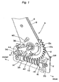
- the recliner adjuster A is attached to an automotive seat, a recliner or the like, and includes a pair of first brackets 2, 4 attached to a seat cushion (not shown) and a pair of second brackets 6, 8 attached to a seat back (not shown).
- a worm gear 10 is attached rotatably to the first brackets 2, 4, while a sector gear 12 is fixed to the second brackets 6, 8.
- the worm gear 10 and sector gear 12 have a larger lead angle than the friction angle and is held in engagement with each other.
- the front end of the worm gear 10 is supported rotatably by a front bearing 14, and the rear end of the worm gear 10 is supported rotatably by a rear bearing 16.
- Two thrust bearings 18, 20 disposed in front of and behind the rear bearing 16 are fixed to a rear end portion of the worm gear 10.
- a washer 22, cam 24, and brake ring 26 are attached in this sequence to the front end of the worm gear 10, and a split brake shoe 30 is provided by way of two rollers 28, 28 around the cam 24.
- a circumferential groove 30a is formed in a center portion in the axial direction on the outer surface of the brake shoe 30, and the split brake shoe 30 is biased inward in the radial direction by an arc-shaped spring 32 fitted into the groove 30a.
- the brake ring 26 and brake shoe 30 are housed respectively in the front bearing 14 and brake drum 34 supported by the first brackets 2, 4.
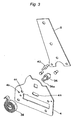
- a circular hole 12a is formed in the sector gear 12 at the center thereof, and a center shaft 36 loosely inserted in the circular hole 12a is attached to the first brackets 2, 4.
- the sector gear 12 is attached rotatably about the center shaft 36.
- a slit 36a is formed in the center shaft 36 on one side thereof. Because one end of a balance spring 38, of which the other end is engaged with the slit 36a, is engaged by an engaging shaft 40 attached to the second brackets 6, 8, the seat back is continually biased forward due to the elastic force of the balance spring 38.
- a guide groove 12c is formed between the circular hole 12a and teeth 12b of the sector gear 12 so as to extend in the circumferential direction, and a roller 42 is loosely inserted in the guide groove 12c.
- the roller 42 is further inserted in tapered grooves 2a, 4a defined in the first brackets 2, 4, and opposite ends thereof are held by a roller holder 44 attached rockingly to the center shaft 36.
- the roller holder 44 is continually biased in the direction of an arrow P by the elastic force of a coil spring 45 (Fig. 5), opposite ends of which are engaged with the first bracket 2 and the tip end 44a of the roller holder 44, respectively.
- An operation lever 46 is disposed laterally outwardly of the first bracket 2, and an operation knob (not shown), which a seat occupant holds, is attached to a front end 46a of the operation lever 46.
- a second link 50 is connected to the operation lever 46 by way of a first link 48, and two vertically extending shafts 52, 54 are secured to a front end portion of the second link 50.
- the shafts 52, 54 are loosely inserted in small-diameter holes 2b, 4b and large-diameter holes 2c, 4c formed in the first bracket 2, 4, and a lock member 56 is mounted on the shafts 52, 54.
- An uneven surface is formed at the tip end of the lock member 56, and this uneven surface opposes a serration formed in the circumference of the brake ring 26 by way of an upper opening 14a of the front bearing 14.
- the operation lever 46 is biased in the direction of an arrow Q by a coil spring (not shown) engaged by a pin 58 secured to the first bracket 2 and the rear end 46b thereof, the lock member 56 is continually biased, about the shaft 52, in the direction of an arrow R in which the tip end thereof abuts the serration of the brake ring 26.
- the recliner adjuster A of the above-mentioned configuration operates as follows.
- the operation lever 46 In the normal state, in which the operation lever 46 is not being operated, the operation lever 46 is biased in the direction of the arrow Q by the coil spring engaged with the rear end 46b of the operation lever 46, and the lock member 56, which is connected to the shaft 52 loosely inserted in the small-diameter holes 2b, 4b and the shaft 54 loosely inserted in the large-diameter holes 2c, 4c, is continually subjected to the urging force in the direction of the arrow R. Accordingly, the tip end of the lock member 56 engages with (abuts) the brake ring 26 by way of the upper opening 14a of the front bearing 14 and prevents rotation of the brake ring 26. Because the brake ring 26 is integrally supported by the front end portion of the worm gear 10 whereby rotation of the worm gear 10 is prevented, the inclination of the seat back with respect to the seat cushion is maintained.
- the seat back is tilted forward by the elastic force of the balance spring 38, or it is tilted backward by a seat occupant applying a load in the backward direction to the seat back.
- the tip end of the lock member 56 re-engages with the outer circumferential surface of the brake ring 26 whereby rotation of the worm gear 10 is prevented, thus maintaining the inclination of the seat back at its current angle.
- the brake shoe 30 When the worm gear 10 is rotated at a rotational speed above a predetermined value, the brake shoe 30 is caused to spread out by the centrifugal force thereof whereby the outer circumferential surface thereof abuts the inner circumferential surface of the brake drum 34 to lock the worm gear 10.
- the setting of the rotational speed and rotational acceleration of the worm gear 10 is carried out on the basis of the mass of the brake shoe 30 and the elastic force of the arc-shaped spring 32 which biases the brake shoe 30 inward.
- the roller holder 44 is biased in the direction of the arrow P by the elastic force of a coil spring engaged with the tip end 44a thereof, the roller 42 supported by the roller holder 44 is continually biased in the direction of the arrow S. Because the tapered grooves 2a, 4a formed in the first bracket 2, 4 and the guide groove 12c formed in the circumferential direction of the sector gear 12 intersect at a predetermined angle, the roller 42 is, by the elastic force of the coil spring 45, thrust into a space between the roller holder 44 and sector gear 12, like a wedge, while abutting the upper edges of the tapered grooves 2a, 4a, thereby biasing the sector gear 12 downward toward the worm gear 10.
- the roller 42 acts as a pressing member for the sector gear 12.
Landscapes
- Engineering & Computer Science (AREA)
- Aviation & Aerospace Engineering (AREA)
- Transportation (AREA)
- Mechanical Engineering (AREA)
- Chairs For Special Purposes, Such As Reclining Chairs (AREA)
- Seats For Vehicles (AREA)
- Gear Transmission (AREA)
Claims (1)
- Vorrichtung zum Reduzieren des Totgangs für eine Stuhleinstellvorrichtung (A), welche an einem Stuhl befestigt ist, der ein Sitzkissen und eine Rückenlehne und einen Beschlag (2;4) aufweist, der an dem Sitzkissen befestigt ist, wobei die Vorrichtung zum Reduzieren des Totgangs umfasst:dadurch gekennzeichnet, dass im Beschlag eine sich verjüngende Nut (2a;4a) ausgebildet ist, wobei das Druckelement eine Rolle (42) umfasst, die schwenkbar an dem Zahnradabschnitt (12) befestigt ist und beweglich in die sich verjüngende Nut (2a;4a) eingesetzt und entlang einer Kante der sich verjüngenden Nut (2a;4a) vorgespannt ist, um den Zahnradabschnitt (12) an die Schnecke (10) zu pressen.eine Schnecke (10), welche drehbar an dem Sitzkissen befestigt ist;einen Zahnradabschnitt (12), welcher an der Rückenlehne befestigt und in Eingriff mit der Schnecke gehalten ist; undein Druckelement (42,44,45) zum Pressen des Zahnradabschnitts (12) an die Schnecke (10), um Totgang zwischen diesen zu verringern,
Applications Claiming Priority (2)
| Application Number | Priority Date | Filing Date | Title |
|---|---|---|---|
| JP16088699A JP4311818B2 (ja) | 1999-06-08 | 1999-06-08 | リクライニングアジャスタのバックラッシ低減構造 |
| JP16088699 | 1999-06-08 |
Publications (3)
| Publication Number | Publication Date |
|---|---|
| EP1059193A2 EP1059193A2 (de) | 2000-12-13 |
| EP1059193A3 EP1059193A3 (de) | 2002-02-06 |
| EP1059193B1 true EP1059193B1 (de) | 2005-11-09 |
Family
ID=15724502
Family Applications (1)
| Application Number | Title | Priority Date | Filing Date |
|---|---|---|---|
| EP00112117A Expired - Lifetime EP1059193B1 (de) | 1999-06-08 | 2000-06-06 | Spielausgleichstruktur für Neigungsverstellvorrichtung |
Country Status (5)
| Country | Link |
|---|---|
| US (1) | US6428104B1 (de) |
| EP (1) | EP1059193B1 (de) |
| JP (1) | JP4311818B2 (de) |
| KR (1) | KR100380572B1 (de) |
| DE (1) | DE60023791T2 (de) |
Families Citing this family (22)
| Publication number | Priority date | Publication date | Assignee | Title |
|---|---|---|---|---|
| US7066543B2 (en) * | 2001-01-05 | 2006-06-27 | Fisher Dynamics Corporation | Powered fold-flat seat hinge assembly |
| US7239096B2 (en) * | 2002-02-12 | 2007-07-03 | Johnson Controls Technology Company | Vehicle seat having an electronic control system |
| ATE331645T1 (de) * | 2002-02-12 | 2006-07-15 | Johnson Controls Tech Co | Kraftfahrzeugsitz mit aktiver rückenlehne |
| US6764136B2 (en) * | 2002-02-26 | 2004-07-20 | Delta Tooling Co., Ltd. | Reclining adjuster |
| JP4184775B2 (ja) * | 2002-12-12 | 2008-11-19 | 株式会社デルタツーリング | リクライニングアジャスタ |
| JP4512423B2 (ja) * | 2004-06-04 | 2010-07-28 | 株式会社デルタツーリング | リクライニングアジャスタ |
| JP4528041B2 (ja) * | 2004-07-07 | 2010-08-18 | 株式会社デルタツーリング | リクライニングアジャスタ |
| JP4998867B2 (ja) | 2005-01-27 | 2012-08-15 | 株式会社デルタツーリング | リクライニングアジャスタ |
| US7246858B2 (en) * | 2005-07-19 | 2007-07-24 | Long-Chuan Hsu | Structure to adjust a seat back |
| DE602006019181D1 (de) * | 2005-09-20 | 2011-02-10 | Mazda Motor | Vorrichtung für Kraftfahrzeugsitze |
| WO2007043233A1 (ja) * | 2005-10-12 | 2007-04-19 | Delta Tooling Co., Ltd. | リクライニングアジャスタ |
| US7735927B2 (en) * | 2006-07-28 | 2010-06-15 | Honda Motor Co., Ltd. | Anti-backlash resistant gearing for a seat mechanism |
| US20090021066A1 (en) * | 2007-07-17 | 2009-01-22 | Lear Corporation | Smartfold power drive |
| US7775594B2 (en) * | 2008-08-01 | 2010-08-17 | Bae Industries, Inc. | Power seat assembly with motor actuated spring release and rewind of a seatback sector and with the motor removed from an inertial load path such as during an impact event |
| TWI477844B (zh) * | 2009-03-24 | 2015-03-21 | Asustek Comp Inc | 具有可調整角度功能的電子裝置 |
| JP5278268B2 (ja) * | 2009-09-25 | 2013-09-04 | 株式会社今仙電機製作所 | シート装置 |
| JP4985744B2 (ja) * | 2009-10-28 | 2012-07-25 | 株式会社今仙電機製作所 | シート装置 |
| DE102010049479A1 (de) * | 2010-10-27 | 2012-05-03 | Dr. Ing. H.C. F. Porsche Aktiengesellschaft | Verstellvorrichtung für eine zu verstellende Fahrzeugbaugruppe |
| US9145072B2 (en) | 2010-11-24 | 2015-09-29 | Everett Sollars | Power disc style seat recliner |
| US8550559B2 (en) * | 2010-11-24 | 2013-10-08 | Everett Sollars | Power disc style seat recliner |
| CN105358367B (zh) * | 2013-07-04 | 2017-07-07 | 株式会社三角工具加工 | 旋转动作控制机构及座椅 |
| DE102014208076A1 (de) * | 2013-10-23 | 2015-05-07 | Johnson Controls Components Gmbh & Co. Kg | Elektrisch betriebener Lehnenversteller und Fahrzeugsitz mit einem solchen Lehnenversteller |
Family Cites Families (11)
| Publication number | Priority date | Publication date | Assignee | Title |
|---|---|---|---|---|
| JPS427950Y1 (de) | 1964-05-11 | 1967-04-20 | ||
| DE1625013A1 (de) * | 1967-05-05 | 1970-06-11 | Bosch Gmbh Robert | Antriebsvorrichtung,insbesondere fuer Scheibenwischer |
| GB2117484B (en) * | 1982-03-09 | 1986-03-12 | Richardsons Westgarth And Co L | Valve actuating gearing |
| US4528862A (en) * | 1983-12-20 | 1985-07-16 | North American Philips Corporation | Precision gear mount |
| US4685735A (en) * | 1985-03-18 | 1987-08-11 | Ferro Manufacturing Corporation | Tilt worm recliner |
| JPS643367A (en) * | 1987-06-25 | 1989-01-09 | Asmo Co Ltd | Adjusting structure for backlash of gear |
| US5295730A (en) * | 1991-12-18 | 1994-03-22 | Itt Corporation | Double enveloping worm and gear seat recliner |
| US5590562A (en) * | 1993-11-12 | 1997-01-07 | Brose Fahrzeugteile Gmbh & Co. Kg | Manual passive quick adjustment device |
| JP3881075B2 (ja) | 1997-02-12 | 2007-02-14 | デルタ工業株式会社 | 緊急ロック機構を備えたシートリクライニング装置 |
| JPH10258654A (ja) * | 1997-03-18 | 1998-09-29 | Delta Tsuuring:Kk | リクライニングシート |
| JPH11160886A (ja) | 1997-11-21 | 1999-06-18 | Nec Toyama Ltd | 露光プリンター用焼枠 |
-
1999
- 1999-06-08 JP JP16088699A patent/JP4311818B2/ja not_active Expired - Fee Related
-
2000
- 2000-06-06 DE DE60023791T patent/DE60023791T2/de not_active Expired - Lifetime
- 2000-06-06 EP EP00112117A patent/EP1059193B1/de not_active Expired - Lifetime
- 2000-06-07 KR KR10-2000-0031023A patent/KR100380572B1/ko not_active IP Right Cessation
- 2000-06-08 US US09/589,206 patent/US6428104B1/en not_active Expired - Lifetime
Also Published As
| Publication number | Publication date |
|---|---|
| EP1059193A2 (de) | 2000-12-13 |
| JP4311818B2 (ja) | 2009-08-12 |
| DE60023791T2 (de) | 2006-06-01 |
| JP2000342371A (ja) | 2000-12-12 |
| US6428104B1 (en) | 2002-08-06 |
| DE60023791D1 (de) | 2005-12-15 |
| EP1059193A3 (de) | 2002-02-06 |
| KR20010049496A (ko) | 2001-06-15 |
| KR100380572B1 (ko) | 2003-04-18 |
Similar Documents
| Publication | Publication Date | Title |
|---|---|---|
| EP1059193B1 (de) | Spielausgleichstruktur für Neigungsverstellvorrichtung | |
| US7192090B2 (en) | Recliner adjuster | |
| EP1340648B1 (de) | Neigungseinsteller | |
| US7878593B2 (en) | Anti back drive device for a seat recliner | |
| US5216936A (en) | Mechanism for adjusting the back portion of a seat | |
| US7144082B2 (en) | Seat reclining apparatus for automotive vehicle | |
| US20070096529A1 (en) | Recliner apparatus for vehicle seat | |
| JP4521638B2 (ja) | シートレール装置 | |
| US4576412A (en) | Seat reclining mechanism | |
| US6976738B2 (en) | Recliner adjuster | |
| WO2007043628A1 (ja) | リクライニングアジャスタ | |
| EP1059192A2 (de) | Stufenlose Verstellungsvorrichtung mit Sicherheitsschloss für Kraftfahrzeuge | |
| WO1999056982A1 (en) | Manually actuated seat adjuster | |
| JP2577950Y2 (ja) | シートリクライニング装置 | |
| JPS6365325B2 (de) | ||
| EP1700736A2 (de) | Neigungsverstellvorrichtung | |
| JPS5822603Y2 (ja) | 自動車用シ−トのリクライニング装置 | |
| EP0976606A1 (de) | Neigungsverstellsystem für einen Sitz | |
| JPS6341961Y2 (de) | ||
| JPH0212908Y2 (de) | ||
| JPH08131291A (ja) | シートのリクライニング装置 | |
| JP2581044Y2 (ja) | シートリクライニング装置 | |
| JPH0357761B2 (de) | ||
| JP2540024Y2 (ja) | リクライニング装置 | |
| JPH0686718A (ja) | リクライニング装置 |
Legal Events
| Date | Code | Title | Description |
|---|---|---|---|
| PUAI | Public reference made under article 153(3) epc to a published international application that has entered the european phase |
Free format text: ORIGINAL CODE: 0009012 |
|
| 17P | Request for examination filed |
Effective date: 20000627 |
|
| AK | Designated contracting states |
Kind code of ref document: A2 Designated state(s): AT BE CH CY DE DK ES FI FR GB GR IE IT LI LU MC NL PT SE Kind code of ref document: A2 Designated state(s): DE FR GB |
|
| AX | Request for extension of the european patent |
Free format text: AL;LT;LV;MK;RO;SI |
|
| PUAL | Search report despatched |
Free format text: ORIGINAL CODE: 0009013 |
|
| AK | Designated contracting states |
Kind code of ref document: A3 Designated state(s): AT BE CH CY DE DK ES FI FR GB GR IE IT LI LU MC NL PT SE |
|
| AX | Request for extension of the european patent |
Free format text: AL;LT;LV;MK;RO;SI |
|
| AKX | Designation fees paid |
Free format text: DE FR GB |
|
| 17Q | First examination report despatched |
Effective date: 20031208 |
|
| GRAP | Despatch of communication of intention to grant a patent |
Free format text: ORIGINAL CODE: EPIDOSNIGR1 |
|
| GRAS | Grant fee paid |
Free format text: ORIGINAL CODE: EPIDOSNIGR3 |
|
| GRAA | (expected) grant |
Free format text: ORIGINAL CODE: 0009210 |
|
| AK | Designated contracting states |
Kind code of ref document: B1 Designated state(s): DE FR GB |
|
| REG | Reference to a national code |
Ref country code: GB Ref legal event code: FG4D |
|
| REF | Corresponds to: |
Ref document number: 60023791 Country of ref document: DE Date of ref document: 20051215 Kind code of ref document: P |
|
| ET | Fr: translation filed | ||
| PLBE | No opposition filed within time limit |
Free format text: ORIGINAL CODE: 0009261 |
|
| STAA | Information on the status of an ep patent application or granted ep patent |
Free format text: STATUS: NO OPPOSITION FILED WITHIN TIME LIMIT |
|
| 26N | No opposition filed |
Effective date: 20060810 |
|
| PGFP | Annual fee paid to national office [announced via postgrant information from national office to epo] |
Ref country code: FR Payment date: 20100526 Year of fee payment: 11 |
|
| PGFP | Annual fee paid to national office [announced via postgrant information from national office to epo] |
Ref country code: GB Payment date: 20100624 Year of fee payment: 11 Ref country code: DE Payment date: 20100707 Year of fee payment: 11 |
|
| GBPC | Gb: european patent ceased through non-payment of renewal fee |
Effective date: 20110606 |
|
| REG | Reference to a national code |
Ref country code: FR Ref legal event code: ST Effective date: 20120229 |
|
| REG | Reference to a national code |
Ref country code: DE Ref legal event code: R119 Ref document number: 60023791 Country of ref document: DE Effective date: 20120103 |
|
| PG25 | Lapsed in a contracting state [announced via postgrant information from national office to epo] |
Ref country code: FR Free format text: LAPSE BECAUSE OF NON-PAYMENT OF DUE FEES Effective date: 20110630 Ref country code: DE Free format text: LAPSE BECAUSE OF NON-PAYMENT OF DUE FEES Effective date: 20120103 |
|
| PG25 | Lapsed in a contracting state [announced via postgrant information from national office to epo] |
Ref country code: GB Free format text: LAPSE BECAUSE OF NON-PAYMENT OF DUE FEES Effective date: 20110606 |