EP1056931B1 - Dispositif d'etancheite, et utilisation d'un dispositif d'etancheite - Google Patents
Dispositif d'etancheite, et utilisation d'un dispositif d'etancheite Download PDFInfo
- Publication number
- EP1056931B1 EP1056931B1 EP99914414A EP99914414A EP1056931B1 EP 1056931 B1 EP1056931 B1 EP 1056931B1 EP 99914414 A EP99914414 A EP 99914414A EP 99914414 A EP99914414 A EP 99914414A EP 1056931 B1 EP1056931 B1 EP 1056931B1
- Authority
- EP
- European Patent Office
- Prior art keywords
- gap
- sealing
- seal arrangement
- sealing element
- rotation
- Prior art date
- Legal status (The legal status is an assumption and is not a legal conclusion. Google has not performed a legal analysis and makes no representation as to the accuracy of the status listed.)
- Expired - Lifetime
Links
Images


Classifications
-
- F—MECHANICAL ENGINEERING; LIGHTING; HEATING; WEAPONS; BLASTING
- F01—MACHINES OR ENGINES IN GENERAL; ENGINE PLANTS IN GENERAL; STEAM ENGINES
- F01D—NON-POSITIVE DISPLACEMENT MACHINES OR ENGINES, e.g. STEAM TURBINES
- F01D11/00—Preventing or minimising internal leakage of working-fluid, e.g. between stages
- F01D11/02—Preventing or minimising internal leakage of working-fluid, e.g. between stages by non-contact sealings, e.g. of labyrinth type
- F01D11/025—Seal clearance control; Floating assembly; Adaptation means to differential thermal dilatations
-
- F—MECHANICAL ENGINEERING; LIGHTING; HEATING; WEAPONS; BLASTING
- F01—MACHINES OR ENGINES IN GENERAL; ENGINE PLANTS IN GENERAL; STEAM ENGINES
- F01D—NON-POSITIVE DISPLACEMENT MACHINES OR ENGINES, e.g. STEAM TURBINES
- F01D11/00—Preventing or minimising internal leakage of working-fluid, e.g. between stages
- F01D11/001—Preventing or minimising internal leakage of working-fluid, e.g. between stages for sealing space between stator blade and rotor
-
- F—MECHANICAL ENGINEERING; LIGHTING; HEATING; WEAPONS; BLASTING
- F16—ENGINEERING ELEMENTS AND UNITS; GENERAL MEASURES FOR PRODUCING AND MAINTAINING EFFECTIVE FUNCTIONING OF MACHINES OR INSTALLATIONS; THERMAL INSULATION IN GENERAL
- F16J—PISTONS; CYLINDERS; SEALINGS
- F16J15/00—Sealings
- F16J15/16—Sealings between relatively-moving surfaces
- F16J15/32—Sealings between relatively-moving surfaces with elastic sealings, e.g. O-rings
- F16J15/3284—Sealings between relatively-moving surfaces with elastic sealings, e.g. O-rings characterised by their structure; Selection of materials
- F16J15/3288—Filamentary structures, e.g. brush seals
-
- F—MECHANICAL ENGINEERING; LIGHTING; HEATING; WEAPONS; BLASTING
- F05—INDEXING SCHEMES RELATING TO ENGINES OR PUMPS IN VARIOUS SUBCLASSES OF CLASSES F01-F04
- F05D—INDEXING SCHEME FOR ASPECTS RELATING TO NON-POSITIVE-DISPLACEMENT MACHINES OR ENGINES, GAS-TURBINES OR JET-PROPULSION PLANTS
- F05D2240/00—Components
- F05D2240/55—Seals
- F05D2240/56—Brush seals
Definitions
- the invention relates to a sealing arrangement for sealing an axial gap of a thermal fluid machine, which between a component rotatable about the axis of rotation and one opposite the axis of rotation fixed component formed is.
- the invention further relates to the use of a Sealing arrangement for sealing an axial gap between a blade and a vane of a steam turbine.
- EP 0 611 905 A1 describes a device for non-contact Sealing a radial gap between rooms different Pressure, in particular for a turbomachine described.
- shaft passages between Clear different pressures with suitable seals be provided.
- the specified device consists of a Labyrinth seal, with the stepped labyrinth gap between a rotating and a fixed part are.
- the sealing tips between fixed and rotating parts are as close as possible to each other arranged so that a seal in the radial direction of a gap extending in the axial direction.
- the sealing tips are directed radially so that the Seal tips of two adjacent steps overlap.
- a Group of sealing tips can be made using a caulking wire be caulked into a corresponding groove.
- DE 38 36 474 C2 has a brush seal consisting of two end plates and a package arranged between them tightly packed bristles. The bristles protrude their free ends beyond the end plates.
- the brushes are summarized in a plurality of segments, which Segments in the main plane of the seal each by one Gap arranged in succession separated from each other are.
- the brush seal is used to seal one radial gap between two circumferential relative Components.
- a radial gap seal is described in DE 34 25 162 C2, the one in the manner of a parallel bristle Formed brush seal, the bristles inclined are to the axis of a rotating machine part. More radial gap seals with bristles that form a brush seal, are in the Austrian patent specification 33 252 dated June 10, 1908, U.S. Patent 5,316,318 and WO 92/05378 A1.
- the object of the invention is an alternative sealing arrangement to reduce gap losses in one Gap between a rotatable component and a fixed one Component may occur. Another The object of the invention is to specify a use a sealing arrangement.
- the first-mentioned object is achieved by a Sealing arrangement for sealing an axial gap in a thermal fluid machine, solved, the gap between one around Rotation axis rotatable, a rotor blade designating Component and a fixed with respect to the axis of rotation, a component having a guide vane is formed, the rotatable component having a shaft of thermal fluid machine is connected, and being with a brush-like, Bristle sealing element which protrudes into the gap a seal is achieved.
- a thermal fluid machine can be a steam turbine, a gas turbine, be a compressor or the like with a fluid that is a gas or steam.
- An axial gap is a gap whose main direction of expansion is directed perpendicular to the axis of rotation.
- the The gap can be between ⁇ 45 ° around the perpendicular to the axis of rotation, in particular ⁇ 15 °.
- a fluid is transported to the axis of rotation towards or away from this.
- a radial gap however, a fluid is transported in the direction of the Axis of rotation.
- the axial gap thus extends along an expansion direction that is opposite to the axis of rotation is inclined.
- the invention is based on the knowledge that it is Reduction of gap losses is possible, a seal to achieve an axial gap, at least in some areas extends in the direction of the axis of rotation and a Flow through a fluid in a direction opposite to the axis of rotation allows inclined direction.
- This is also additionally or solely a reduction in gap losses given by a radial gap that matches the axial gap is directly connected in terms of flow technology.
- a brush-like sealing element with bristles is also a particularly effective seal axial gap between a fixed component and given a rotating component, by using of bristles the sealing element is almost completely over the Extend the gap from one component to the other component can.
- the bristles also allow an axial gap change (Change, in particular reduction, of the gap width) of up to 2 cm without being damaged at constant sealing effect.
- the bristles of the sealing element are preferably tightly packed, so that they have the cross section formed by the gap close almost completely.
- the sealing element as well as the Bristles are preferably at an axial angle to the Axis of rotation inclined.
- This axial angle which is both in mathematically positive as well as negative direction the axis of rotation can preferably be in terms of amount below 40 °. In particular, it is in the range of about ⁇ 20 °, preferably in the range between ⁇ 8 °.
- the sealing element can also be substantially parallel to the axis of rotation be directed.
- the sealing arrangement preferably has two or more sealing elements, which together form one Form sealing ring.
- This sealing ring is almost completely blocked the cross section of the gap, so that thereby the training a leakage flow of a fluid, such as steam (water vapor) or Hot gas, is largely prevented.
- a fluid such as steam (water vapor) or Hot gas
- the direction of expansion of the gap is preferably approximately 90 ° inclined to the axis of rotation, so that a classic Axial gap in contrast to a radial gap is.
- the sealing arrangement is preferably in a thermal fluid machine in particular a steam turbine, a gas turbine or a turbogenerator used.
- the rotatable component is preferably with a shaft of the turbomachine connected.
- the sealing arrangement is particularly suitable to seal an axial gap between one Guide and a rotor blade or vice versa between one Rotor blade and a guide blade of a thermal fluid machine.
- There the pressure difference in this axial gap is small the bristles of the brush-like sealing element in axial Design very flexible.
- the pressure difference in the axial gap significantly less than in one radial gap between the blade and the housing and between Guide vane and shaft.
- the sealing element is preferably in the fixed component arranged and can also be moved in this be designed.
- the bristles between two axially displaceable clamps be clamped.
- the axial movement of the sealing element can by using springs and holding projections or the like be limited to a certain amount. It is also possible to close the sealing element with the rotating component connect.
- the directed to use a seal assembly Task is accomplished through the use of a seal assembly for sealing an axial gap in a steam turbine solved, the gap between a blade and a is formed by this axially spaced vane, and a brush-like sealing element with bristles essentially spanning the gap from the guide vane extends in the direction of the blade.
- This is an effective one Sealing of the axial gap given at the even with a relative movement of the blade to the guide blade Damage to the rotor blade in the axial direction or guide vane and the sealing element largely avoided is.
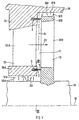
- FIG 1 is a section of a not shown thermal flow machine for example a gas turbine or Steam turbine, shown in a longitudinal section.
- the Thermal fluid machine has a turbine shaft 15 which extends along a Rotation axis 16 extends.
- the turbine shaft 15 are a plurality of rotatable axially spaced apart and also arranged side by side in the circumferential direction Components 12 (blades 12) connected.
- In the circumferential direction form adjacent blades 12 a row of blades (rotor blade grille, rotor blade ring), only one is shown here for the sake of clarity is.
- Each blade 12 is substantially vertical directed to the turbine shaft 15 and has one of the turbine shaft 15 facing cover tape 18B.
- the shroud 18B is adjacent and has a housing 19 of the thermal fluid machine exemplary two sealing tips directed towards the housing 19 16B. There may also be more or fewer sealing tips 16B be provided. There is also a sealing tip on the housing 19 16B is provided facing the blade 12. Between the cover band 18B and the turbine shaft 15 have the Blade 12 has a blade profile area 20B. Between two blades spaced apart in the circumferential direction 12 is characterized by the adjacent blade profile areas 20B shows a throughflow opening, not shown formed for a flow 22 of an action fluid, which the drive of the blade 12 and thus the rotation the turbine shaft 15 is used.
- a guide vane arrangement with a A plurality of guide vanes 13 provided with the housing 19 is connected.
- the one shown in longitudinal section Guide vane 13 also has a cover band 18A, which is adjacent to the turbine shaft 15.
- a blade profile area 20A which is the deflection of the Flow 25 of the action fluid is used.
- a radial gap 17A is formed between the shroud 18A and the turbine shaft 15 .
- a radial gap 17B between the housing 19 is analogous and the shroud 18B of the blade 12.
- In the radial gap 17A project substantially perpendicular to the axis of rotation 10 extended sealing tips 16A. Are alternating the sealing tips 16A with the turbine shaft 15 and the shroud 18A of the guide vane 13 connected.
- thermal fluid machine flows through radial gaps 17A and 17B, respectively Leakage flow 23, which is from the flow 22 of the action fluid is branched off.
- Leakage flow 23 which is from the flow 22 of the action fluid is branched off.
- Between the guide vane 13 and The blade 12 is also in the area of the respective shrouds 18B and 18A an axial gap 11 due to the axial spacing the blade 12 is formed by the guide blade 13.
- the axial gap 11 is essentially in an expansion direction 14 directed, the direction of expansion 14 is perpendicular to the axis of rotation 10.
- a sealing arrangement 1 is provided which has a sealing element 2 has.
- the sealing element 2 lies on a turbine shaft 15 surrounding arranged in the guide vane 13, annular sealing ring 4 (see Figure 3).
- each sealing element 2 has a plurality of bristles 3.
- the bristles 3 essentially extend from the guide vane 13 parallel to the axis of rotation 10 to the rotor blade 12 out.
- the Bristles 3 protrude to the blade 12, touch it or have a small distance from it.
- the sealing ring 4 is formed, which is the axial Gap 11 closes almost completely. This makes one special effective sealing of the axial gap 11 and thus also upstream of this one or this one achieved downstream radial gap 17A, 17B.
- the Leakage current 23 is thereby significantly reduced, so that the Flow 22 of the action fluid almost completely through the Blade profile areas 20A, 20B is guided.
- a longitudinal section is also not closer thermal fluid machine shown shown in a section.
- the same reference numerals have the same meaning as in the figure 1.
- the sealing element 2 is different from that in Figure 1 shown sealing element 2 with respect to the axis of rotation 10 by an axial angle ⁇ of approximately 15 ° to 20 °, preferably about 8 °, inclined. This is when the bristles are touched 3 of the sealing element 2 with the rotor blade 12 a bend the bristles in a common direction and thus achieved a particularly effective seal of the axial gap 11.
- FIG. 3 is a cross section through the turbine shaft 15 and through the cover band 18A of the guide vane 13 according to FIG. 1 shown.
- the cover band 18A is through a dividing joint 21 divided into two symmetrical halves, each half consisting of a large number of partial cover tapes of the respectively assigned Guide vanes 13 (not shown) is formed. It is also possible that the shroud 18A in a plurality of Segments, e.g. eight 45 ° segments.
- the bristles 3 are combined in a sealing ring 4, which is also consists of two symmetrical parts, which at the division joint 21 are separable.
- the sealing ring 4 this can for example in the context of maintenance work or repair work simply checked on the turbo machine or be replaced.
- the invention is characterized by a brush-like sealing element from, which in an axial gap between a rotating component and a fixed component, especially a thermal fluid machine protrudes and with it one effective sealing of the axial gap guaranteed.
- a brush-like sealing element from which in an axial gap between a rotating component and a fixed component, especially a thermal fluid machine protrudes and with it one effective sealing of the axial gap guaranteed.
Claims (10)
- Dispositif (1) d'étanchéité pour rendre étanche un jeu (11) axial dans une turbomachine thermique, ce jeu (11) étant formé entre un élément (12) qui peut toumer par rapport à l'axe (10) de rotation et qui comporte une aube mobile et un élément (13) qui est fixe par rapport à l'axe (10) de rotation et qui comporte une aube directrice, l'élément (12) qui peut tourner étant relié à un arbre (15) de la turbomachine par un élément (2) d'étanchéité du type à brosse ayant des soies (3), qui fait saillie dans le jeu (11).
- Dispositif (1) d'étanchéité suivant la revendication 1, dans lequel l'élément (2) d'étanchéité a des soies (3) drues.
- Dispositif (1) d'étanchéité suivant la revendication 1 ou 2, dans lequel l'élément (2) d'étanchéité est incliné par rapport à l'axe (10) de rotation d'un angle axial, notamment inférieur à 20° et de préférence d'environ 8°.
- Dispositif (1) d'étanchéité suivant la revendication 1 ou 2, dans lequel l'élément (2) d'étanchéité est dirigé sensiblement parallèlement à l'axe (10) de rotation.
- Dispositif (1) d'étanchéité suivant l'une des revendications précédentes, dans lequel le jeu (11) axial s'étend le long d'une direction (14), la direction (14) étant inclinée d'environ 90° par rapport à l'axe (10) de rotation.
- Dispositif (1) d'étanchéité suivant l'une des revendications précédentes, dans lequel les soies (3) peuvent être courbées élastiquement et en étant souples en flexion.
- Dispositif (1) d'étanchéité suivant l'une des revendications précédentes, qui a deux éléments (2) d'étanchéité ou plusieurs éléments (2) d'étanchéité qui forment ensemble un anneau (4) d'étanchéité.
- Dispositif (1) d'étanchéité suivant l'une des revendications précédentes dans une turbine à vapeur, une turbine à gaz, un compresseur ou un turbogénérateur.
- Dispositif (1) d'étanchéité suivant l'une des revendications précédentes, dans lequel l'élément (2) d'étanchéité est monté notamment coulissant dans l'élément (13) fixe ou dans l'élément (12) tournant.
- Utilisation d'un dispositif (1) d'étanchéité pour rendre étanche un jeu (11) axial dans une turbine à vapeur, le jeu (11) axial étant formé entre une aube (12) mobile et une aube (13) directrice à distance axialement de celle-ci, un élément (2) d'étanchéité du type à brosse ayant des soies (3) s'étendant en recouvrant sensiblement le jeu (11) de l'aube (13) directrice en direction de l'aube (12) mobile.
Applications Claiming Priority (3)
| Application Number | Priority Date | Filing Date | Title |
|---|---|---|---|
| DE19807029 | 1998-02-19 | ||
| DE19807029 | 1998-02-19 | ||
| PCT/DE1999/000389 WO1999042704A1 (fr) | 1998-02-19 | 1999-02-11 | Dispositif d'etancheite, et utilisation d'un dispositif d'etancheite |
Publications (2)
| Publication Number | Publication Date |
|---|---|
| EP1056931A1 EP1056931A1 (fr) | 2000-12-06 |
| EP1056931B1 true EP1056931B1 (fr) | 2002-10-09 |
Family
ID=7858323
Family Applications (1)
| Application Number | Title | Priority Date | Filing Date |
|---|---|---|---|
| EP99914414A Expired - Lifetime EP1056931B1 (fr) | 1998-02-19 | 1999-02-11 | Dispositif d'etancheite, et utilisation d'un dispositif d'etancheite |
Country Status (6)
| Country | Link |
|---|---|
| EP (1) | EP1056931B1 (fr) |
| JP (1) | JP4224210B2 (fr) |
| KR (1) | KR20010041102A (fr) |
| CN (1) | CN1119503C (fr) |
| DE (1) | DE59903021D1 (fr) |
| WO (1) | WO1999042704A1 (fr) |
Families Citing this family (16)
| Publication number | Priority date | Publication date | Assignee | Title |
|---|---|---|---|---|
| US6887038B2 (en) * | 2003-09-02 | 2005-05-03 | General Electric Company | Methods and apparatus to facilitate sealing between rotating turbine shafts |
| DE102005042272A1 (de) * | 2005-09-06 | 2007-03-08 | Mtu Aero Engines Gmbh | Strömungsmaschine sowie Dichtungselement für eine Strömungsmaschine |
| US20070132190A1 (en) * | 2005-12-12 | 2007-06-14 | Charles Trabert | Axial dynamic brush seal |
| DE102007010378A1 (de) * | 2007-03-03 | 2008-09-04 | Mtu Aero Engines Gmbh | Dichtelement zur Abdichtung eines Spaltes zwischen Stator und Rotor einer axialen Strömungsmaschine |
| DE102010026336A1 (de) * | 2010-07-07 | 2012-01-12 | Siemens Aktiengesellschaft | Wellendichtungsvorrichtung |
| US8794918B2 (en) | 2011-01-07 | 2014-08-05 | General Electric Company | System for adjusting brush seal segments in turbomachine |
| US8777563B2 (en) * | 2011-01-31 | 2014-07-15 | General Electric Company | Axial brush seal |
| US9121297B2 (en) | 2011-03-28 | 2015-09-01 | General Electric Company | Rotating brush seal |
| US9255486B2 (en) | 2011-03-28 | 2016-02-09 | General Electric Company | Rotating brush seal |
| FR2974841B1 (fr) * | 2011-05-04 | 2013-06-07 | Snecma | Dispositif d'etancheite pour distributeur de turbine de turbomachine |
| FR3010462B1 (fr) * | 2013-09-11 | 2021-10-08 | Snecma | Secteur angulaire de redresseur pour compresseur de turbomachine comportant un joint d'etancheite a brosse |
| DE102013220276A1 (de) | 2013-10-08 | 2015-04-09 | MTU Aero Engines AG | Strömungsmaschine |
| US10041367B2 (en) * | 2013-12-12 | 2018-08-07 | General Electric Company | Axially faced seal system |
| DE102016211280A1 (de) * | 2016-06-23 | 2017-12-28 | Siemens Aktiengesellschaft | Dampfturbine |
| CN106194279A (zh) * | 2016-08-27 | 2016-12-07 | 朱艳君 | 汽轮机轴向安装刷式汽封 |
| CN114635757B (zh) * | 2022-02-23 | 2023-12-12 | 潍柴动力股份有限公司 | 转子密封装置 |
Family Cites Families (7)
| Publication number | Priority date | Publication date | Assignee | Title |
|---|---|---|---|---|
| AT33252B (de) | 1907-06-22 | 1908-06-10 | Sebastian Ziani De Ferranti | Bürstendichtung für längsbewegliche oder sich drehende Maschinenteile. |
| DE3425162A1 (de) | 1984-07-07 | 1986-01-16 | MTU Motoren- und Turbinen-Union München GmbH, 8000 München | Dichtung zwischen zwei maschinenteilen |
| GB2212228B (en) | 1987-11-13 | 1991-08-07 | Rolls Royce Plc | Enhanced performance brush seals |
| GB9020317D0 (en) | 1990-09-18 | 1990-10-31 | Cross Mfg Co | Sealing devices |
| FR2690493B1 (fr) | 1992-04-23 | 1996-10-25 | Snecma | Joint annulaire a brosse. |
| DE4304805A1 (de) | 1993-02-17 | 1994-08-18 | Abb Patent Gmbh | Vorrichtung zum berührungslosen Abdichten zwischen Räumen unterschiedlichen Druckes |
| DE19519322A1 (de) * | 1995-05-26 | 1996-11-28 | Klein Schanzlin & Becker Ag | Dichtung zwischen Laufrad und Gehäusewand einer Kreiselpumpe |
-
1999
- 1999-02-11 DE DE59903021T patent/DE59903021D1/de not_active Expired - Lifetime
- 1999-02-11 WO PCT/DE1999/000389 patent/WO1999042704A1/fr not_active Application Discontinuation
- 1999-02-11 JP JP2000532620A patent/JP4224210B2/ja not_active Expired - Fee Related
- 1999-02-11 EP EP99914414A patent/EP1056931B1/fr not_active Expired - Lifetime
- 1999-02-11 CN CN99803486A patent/CN1119503C/zh not_active Expired - Fee Related
- 1999-02-11 KR KR1020007009143A patent/KR20010041102A/ko not_active Application Discontinuation
Also Published As
| Publication number | Publication date |
|---|---|
| EP1056931A1 (fr) | 2000-12-06 |
| JP4224210B2 (ja) | 2009-02-12 |
| CN1119503C (zh) | 2003-08-27 |
| WO1999042704A1 (fr) | 1999-08-26 |
| DE59903021D1 (de) | 2002-11-14 |
| KR20010041102A (ko) | 2001-05-15 |
| JP2002504651A (ja) | 2002-02-12 |
| CN1292061A (zh) | 2001-04-18 |
Similar Documents
| Publication | Publication Date | Title |
|---|---|---|
| EP1056931B1 (fr) | Dispositif d'etancheite, et utilisation d'un dispositif d'etancheite | |
| EP1515000B1 (fr) | Aubage d'une turbomachine avec un carenage contouré | |
| DE102012013160B4 (de) | Labyrinthdichtungen | |
| DE2356721C3 (de) | Kühleinrichtung für hohle Laufschaufeln einer axial durchströmten Turbine | |
| DE69736690T2 (de) | Bürstendichtungen und kombinierte Labyrinth- und Bürstendichtungen für drehende Maschinen | |
| EP0799973B1 (fr) | Contour de paroi pour une turbomachine axiale | |
| CH641883A5 (de) | Verfahren und einrichtung zum dichten einer drehbaren welle einer maschine. | |
| DE60127391T2 (de) | Bürstendichtung für turbinen und dergleichen drehvorrichtungen | |
| WO2001083951A1 (fr) | Dispositif permettant d'obturer un interstice | |
| DE10047307A1 (de) | Dichtungsanordnung | |
| WO1986004970A1 (fr) | Joint d'etancheite d'une turbo-machine | |
| EP0591565B1 (fr) | Fixation d'aube statorique pour turbomachine à écoulement axial | |
| DE19914227B4 (de) | Wärmeschutzvorrichtung in Gasturbinen | |
| EP0840042B1 (fr) | Joint à brosses pour dispositif rotor/stator. | |
| DE3503421C3 (de) | Axialverdichter für eine Turbomaschine | |
| DE1011671B (de) | Radialturbomaschine mit einstellbarem Leitapparat | |
| EP0992656B1 (fr) | Turbomachine pour comprimer ou détendre un fluide comprimable | |
| EP2092164B1 (fr) | Turbo machine, en particulier turbine à gaz | |
| DE4100554A1 (de) | Vorrichtung zur spaltabdichtung zwischen benachbarten segmenten von turbinenleitschaufelkraenzen und mantelringen | |
| DE69913880T2 (de) | Dichtung | |
| WO2007028353A1 (fr) | Turbomachine et element d'etancheite pour une turbomachine | |
| DE3207514C1 (de) | Rotor fuer ein Gasturbinentriebwerk | |
| DE2004761A1 (de) | Turbomaschine mit gekühltem Rotor | |
| DE2745130B1 (de) | Dichtungseinrichtung für die freien Schaufelenden von Axialturbinen | |
| EP0520258B1 (fr) | Dispositif de fixation d'aubes de rotor |
Legal Events
| Date | Code | Title | Description |
|---|---|---|---|
| PUAI | Public reference made under article 153(3) epc to a published international application that has entered the european phase |
Free format text: ORIGINAL CODE: 0009012 |
|
| 17P | Request for examination filed |
Effective date: 20000804 |
|
| AK | Designated contracting states |
Kind code of ref document: A1 Designated state(s): CH DE FR GB LI |
|
| GRAG | Despatch of communication of intention to grant |
Free format text: ORIGINAL CODE: EPIDOS AGRA |
|
| 17Q | First examination report despatched |
Effective date: 20020117 |
|
| GRAG | Despatch of communication of intention to grant |
Free format text: ORIGINAL CODE: EPIDOS AGRA |
|
| GRAH | Despatch of communication of intention to grant a patent |
Free format text: ORIGINAL CODE: EPIDOS IGRA |
|
| GRAH | Despatch of communication of intention to grant a patent |
Free format text: ORIGINAL CODE: EPIDOS IGRA |
|
| GRAA | (expected) grant |
Free format text: ORIGINAL CODE: 0009210 |
|
| AK | Designated contracting states |
Kind code of ref document: B1 Designated state(s): CH DE FR GB LI |
|
| REG | Reference to a national code |
Ref country code: GB Ref legal event code: FG4D Free format text: NOT ENGLISH |
|
| REG | Reference to a national code |
Ref country code: CH Ref legal event code: EP |
|
| REG | Reference to a national code |
Ref country code: CH Ref legal event code: NV Representative=s name: SIEMENS SCHWEIZ AG |
|
| REF | Corresponds to: |
Ref document number: 59903021 Country of ref document: DE Date of ref document: 20021114 |
|
| GBT | Gb: translation of ep patent filed (gb section 77(6)(a)/1977) |
Effective date: 20030113 |
|
| ET | Fr: translation filed | ||
| PLBE | No opposition filed within time limit |
Free format text: ORIGINAL CODE: 0009261 |
|
| STAA | Information on the status of an ep patent application or granted ep patent |
Free format text: STATUS: NO OPPOSITION FILED WITHIN TIME LIMIT |
|
| 26N | No opposition filed |
Effective date: 20030710 |
|
| REG | Reference to a national code |
Ref country code: CH Ref legal event code: PCAR Free format text: SIEMENS SCHWEIZ AG;INTELLECTUAL PROPERTY FREILAGERSTRASSE 40;8047 ZUERICH (CH) |
|
| PGFP | Annual fee paid to national office [announced via postgrant information from national office to epo] |
Ref country code: GB Payment date: 20130213 Year of fee payment: 15 Ref country code: FR Payment date: 20130301 Year of fee payment: 15 |
|
| PGFP | Annual fee paid to national office [announced via postgrant information from national office to epo] |
Ref country code: DE Payment date: 20130419 Year of fee payment: 15 Ref country code: CH Payment date: 20130510 Year of fee payment: 15 |
|
| REG | Reference to a national code |
Ref country code: DE Ref legal event code: R119 Ref document number: 59903021 Country of ref document: DE |
|
| REG | Reference to a national code |
Ref country code: CH Ref legal event code: PL |
|
| GBPC | Gb: european patent ceased through non-payment of renewal fee |
Effective date: 20140211 |
|
| PG25 | Lapsed in a contracting state [announced via postgrant information from national office to epo] |
Ref country code: CH Free format text: LAPSE BECAUSE OF NON-PAYMENT OF DUE FEES Effective date: 20140228 Ref country code: LI Free format text: LAPSE BECAUSE OF NON-PAYMENT OF DUE FEES Effective date: 20140228 |
|
| REG | Reference to a national code |
Ref country code: FR Ref legal event code: ST Effective date: 20141031 |
|
| REG | Reference to a national code |
Ref country code: DE Ref legal event code: R119 Ref document number: 59903021 Country of ref document: DE Effective date: 20140902 |
|
| PG25 | Lapsed in a contracting state [announced via postgrant information from national office to epo] |
Ref country code: FR Free format text: LAPSE BECAUSE OF NON-PAYMENT OF DUE FEES Effective date: 20140228 Ref country code: GB Free format text: LAPSE BECAUSE OF NON-PAYMENT OF DUE FEES Effective date: 20140211 Ref country code: DE Free format text: LAPSE BECAUSE OF NON-PAYMENT OF DUE FEES Effective date: 20140902 |