EP1056931B1 - Sealing device and use of a sealing device - Google Patents
Sealing device and use of a sealing device Download PDFInfo
- Publication number
- EP1056931B1 EP1056931B1 EP99914414A EP99914414A EP1056931B1 EP 1056931 B1 EP1056931 B1 EP 1056931B1 EP 99914414 A EP99914414 A EP 99914414A EP 99914414 A EP99914414 A EP 99914414A EP 1056931 B1 EP1056931 B1 EP 1056931B1
- Authority
- EP
- European Patent Office
- Prior art keywords
- gap
- sealing
- seal arrangement
- sealing element
- rotation
- Prior art date
- Legal status (The legal status is an assumption and is not a legal conclusion. Google has not performed a legal analysis and makes no representation as to the accuracy of the status listed.)
- Expired - Lifetime
Links
Images


Classifications
-
- F—MECHANICAL ENGINEERING; LIGHTING; HEATING; WEAPONS; BLASTING
- F01—MACHINES OR ENGINES IN GENERAL; ENGINE PLANTS IN GENERAL; STEAM ENGINES
- F01D—NON-POSITIVE DISPLACEMENT MACHINES OR ENGINES, e.g. STEAM TURBINES
- F01D11/00—Preventing or minimising internal leakage of working-fluid, e.g. between stages
- F01D11/02—Preventing or minimising internal leakage of working-fluid, e.g. between stages by non-contact sealings, e.g. of labyrinth type
- F01D11/025—Seal clearance control; Floating assembly; Adaptation means to differential thermal dilatations
-
- F—MECHANICAL ENGINEERING; LIGHTING; HEATING; WEAPONS; BLASTING
- F01—MACHINES OR ENGINES IN GENERAL; ENGINE PLANTS IN GENERAL; STEAM ENGINES
- F01D—NON-POSITIVE DISPLACEMENT MACHINES OR ENGINES, e.g. STEAM TURBINES
- F01D11/00—Preventing or minimising internal leakage of working-fluid, e.g. between stages
- F01D11/001—Preventing or minimising internal leakage of working-fluid, e.g. between stages for sealing space between stator blade and rotor
-
- F—MECHANICAL ENGINEERING; LIGHTING; HEATING; WEAPONS; BLASTING
- F16—ENGINEERING ELEMENTS AND UNITS; GENERAL MEASURES FOR PRODUCING AND MAINTAINING EFFECTIVE FUNCTIONING OF MACHINES OR INSTALLATIONS; THERMAL INSULATION IN GENERAL
- F16J—PISTONS; CYLINDERS; SEALINGS
- F16J15/00—Sealings
- F16J15/16—Sealings between relatively-moving surfaces
- F16J15/32—Sealings between relatively-moving surfaces with elastic sealings, e.g. O-rings
- F16J15/3284—Sealings between relatively-moving surfaces with elastic sealings, e.g. O-rings characterised by their structure; Selection of materials
- F16J15/3288—Filamentary structures, e.g. brush seals
-
- F—MECHANICAL ENGINEERING; LIGHTING; HEATING; WEAPONS; BLASTING
- F05—INDEXING SCHEMES RELATING TO ENGINES OR PUMPS IN VARIOUS SUBCLASSES OF CLASSES F01-F04
- F05D—INDEXING SCHEME FOR ASPECTS RELATING TO NON-POSITIVE-DISPLACEMENT MACHINES OR ENGINES, GAS-TURBINES OR JET-PROPULSION PLANTS
- F05D2240/00—Components
- F05D2240/55—Seals
- F05D2240/56—Brush seals
Definitions
- the invention relates to a sealing arrangement for sealing an axial gap of a thermal fluid machine, which between a component rotatable about the axis of rotation and one opposite the axis of rotation fixed component formed is.
- the invention further relates to the use of a Sealing arrangement for sealing an axial gap between a blade and a vane of a steam turbine.
- EP 0 611 905 A1 describes a device for non-contact Sealing a radial gap between rooms different Pressure, in particular for a turbomachine described.
- shaft passages between Clear different pressures with suitable seals be provided.
- the specified device consists of a Labyrinth seal, with the stepped labyrinth gap between a rotating and a fixed part are.
- the sealing tips between fixed and rotating parts are as close as possible to each other arranged so that a seal in the radial direction of a gap extending in the axial direction.
- the sealing tips are directed radially so that the Seal tips of two adjacent steps overlap.
- a Group of sealing tips can be made using a caulking wire be caulked into a corresponding groove.
- DE 38 36 474 C2 has a brush seal consisting of two end plates and a package arranged between them tightly packed bristles. The bristles protrude their free ends beyond the end plates.
- the brushes are summarized in a plurality of segments, which Segments in the main plane of the seal each by one Gap arranged in succession separated from each other are.
- the brush seal is used to seal one radial gap between two circumferential relative Components.
- a radial gap seal is described in DE 34 25 162 C2, the one in the manner of a parallel bristle Formed brush seal, the bristles inclined are to the axis of a rotating machine part. More radial gap seals with bristles that form a brush seal, are in the Austrian patent specification 33 252 dated June 10, 1908, U.S. Patent 5,316,318 and WO 92/05378 A1.
- the object of the invention is an alternative sealing arrangement to reduce gap losses in one Gap between a rotatable component and a fixed one Component may occur. Another The object of the invention is to specify a use a sealing arrangement.
- the first-mentioned object is achieved by a Sealing arrangement for sealing an axial gap in a thermal fluid machine, solved, the gap between one around Rotation axis rotatable, a rotor blade designating Component and a fixed with respect to the axis of rotation, a component having a guide vane is formed, the rotatable component having a shaft of thermal fluid machine is connected, and being with a brush-like, Bristle sealing element which protrudes into the gap a seal is achieved.
- a thermal fluid machine can be a steam turbine, a gas turbine, be a compressor or the like with a fluid that is a gas or steam.
- An axial gap is a gap whose main direction of expansion is directed perpendicular to the axis of rotation.
- the The gap can be between ⁇ 45 ° around the perpendicular to the axis of rotation, in particular ⁇ 15 °.
- a fluid is transported to the axis of rotation towards or away from this.
- a radial gap however, a fluid is transported in the direction of the Axis of rotation.
- the axial gap thus extends along an expansion direction that is opposite to the axis of rotation is inclined.
- the invention is based on the knowledge that it is Reduction of gap losses is possible, a seal to achieve an axial gap, at least in some areas extends in the direction of the axis of rotation and a Flow through a fluid in a direction opposite to the axis of rotation allows inclined direction.
- This is also additionally or solely a reduction in gap losses given by a radial gap that matches the axial gap is directly connected in terms of flow technology.
- a brush-like sealing element with bristles is also a particularly effective seal axial gap between a fixed component and given a rotating component, by using of bristles the sealing element is almost completely over the Extend the gap from one component to the other component can.
- the bristles also allow an axial gap change (Change, in particular reduction, of the gap width) of up to 2 cm without being damaged at constant sealing effect.
- the bristles of the sealing element are preferably tightly packed, so that they have the cross section formed by the gap close almost completely.
- the sealing element as well as the Bristles are preferably at an axial angle to the Axis of rotation inclined.
- This axial angle which is both in mathematically positive as well as negative direction the axis of rotation can preferably be in terms of amount below 40 °. In particular, it is in the range of about ⁇ 20 °, preferably in the range between ⁇ 8 °.
- the sealing element can also be substantially parallel to the axis of rotation be directed.
- the sealing arrangement preferably has two or more sealing elements, which together form one Form sealing ring.
- This sealing ring is almost completely blocked the cross section of the gap, so that thereby the training a leakage flow of a fluid, such as steam (water vapor) or Hot gas, is largely prevented.
- a fluid such as steam (water vapor) or Hot gas
- the direction of expansion of the gap is preferably approximately 90 ° inclined to the axis of rotation, so that a classic Axial gap in contrast to a radial gap is.
- the sealing arrangement is preferably in a thermal fluid machine in particular a steam turbine, a gas turbine or a turbogenerator used.
- the rotatable component is preferably with a shaft of the turbomachine connected.
- the sealing arrangement is particularly suitable to seal an axial gap between one Guide and a rotor blade or vice versa between one Rotor blade and a guide blade of a thermal fluid machine.
- There the pressure difference in this axial gap is small the bristles of the brush-like sealing element in axial Design very flexible.
- the pressure difference in the axial gap significantly less than in one radial gap between the blade and the housing and between Guide vane and shaft.
- the sealing element is preferably in the fixed component arranged and can also be moved in this be designed.
- the bristles between two axially displaceable clamps be clamped.
- the axial movement of the sealing element can by using springs and holding projections or the like be limited to a certain amount. It is also possible to close the sealing element with the rotating component connect.
- the directed to use a seal assembly Task is accomplished through the use of a seal assembly for sealing an axial gap in a steam turbine solved, the gap between a blade and a is formed by this axially spaced vane, and a brush-like sealing element with bristles essentially spanning the gap from the guide vane extends in the direction of the blade.
- This is an effective one Sealing of the axial gap given at the even with a relative movement of the blade to the guide blade Damage to the rotor blade in the axial direction or guide vane and the sealing element largely avoided is.
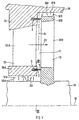
- FIG 1 is a section of a not shown thermal flow machine for example a gas turbine or Steam turbine, shown in a longitudinal section.
- the Thermal fluid machine has a turbine shaft 15 which extends along a Rotation axis 16 extends.
- the turbine shaft 15 are a plurality of rotatable axially spaced apart and also arranged side by side in the circumferential direction Components 12 (blades 12) connected.
- In the circumferential direction form adjacent blades 12 a row of blades (rotor blade grille, rotor blade ring), only one is shown here for the sake of clarity is.
- Each blade 12 is substantially vertical directed to the turbine shaft 15 and has one of the turbine shaft 15 facing cover tape 18B.
- the shroud 18B is adjacent and has a housing 19 of the thermal fluid machine exemplary two sealing tips directed towards the housing 19 16B. There may also be more or fewer sealing tips 16B be provided. There is also a sealing tip on the housing 19 16B is provided facing the blade 12. Between the cover band 18B and the turbine shaft 15 have the Blade 12 has a blade profile area 20B. Between two blades spaced apart in the circumferential direction 12 is characterized by the adjacent blade profile areas 20B shows a throughflow opening, not shown formed for a flow 22 of an action fluid, which the drive of the blade 12 and thus the rotation the turbine shaft 15 is used.
- a guide vane arrangement with a A plurality of guide vanes 13 provided with the housing 19 is connected.
- the one shown in longitudinal section Guide vane 13 also has a cover band 18A, which is adjacent to the turbine shaft 15.
- a blade profile area 20A which is the deflection of the Flow 25 of the action fluid is used.
- a radial gap 17A is formed between the shroud 18A and the turbine shaft 15 .
- a radial gap 17B between the housing 19 is analogous and the shroud 18B of the blade 12.
- In the radial gap 17A project substantially perpendicular to the axis of rotation 10 extended sealing tips 16A. Are alternating the sealing tips 16A with the turbine shaft 15 and the shroud 18A of the guide vane 13 connected.
- thermal fluid machine flows through radial gaps 17A and 17B, respectively Leakage flow 23, which is from the flow 22 of the action fluid is branched off.
- Leakage flow 23 which is from the flow 22 of the action fluid is branched off.
- Between the guide vane 13 and The blade 12 is also in the area of the respective shrouds 18B and 18A an axial gap 11 due to the axial spacing the blade 12 is formed by the guide blade 13.
- the axial gap 11 is essentially in an expansion direction 14 directed, the direction of expansion 14 is perpendicular to the axis of rotation 10.
- a sealing arrangement 1 is provided which has a sealing element 2 has.
- the sealing element 2 lies on a turbine shaft 15 surrounding arranged in the guide vane 13, annular sealing ring 4 (see Figure 3).
- each sealing element 2 has a plurality of bristles 3.
- the bristles 3 essentially extend from the guide vane 13 parallel to the axis of rotation 10 to the rotor blade 12 out.
- the Bristles 3 protrude to the blade 12, touch it or have a small distance from it.
- the sealing ring 4 is formed, which is the axial Gap 11 closes almost completely. This makes one special effective sealing of the axial gap 11 and thus also upstream of this one or this one achieved downstream radial gap 17A, 17B.
- the Leakage current 23 is thereby significantly reduced, so that the Flow 22 of the action fluid almost completely through the Blade profile areas 20A, 20B is guided.
- a longitudinal section is also not closer thermal fluid machine shown shown in a section.
- the same reference numerals have the same meaning as in the figure 1.
- the sealing element 2 is different from that in Figure 1 shown sealing element 2 with respect to the axis of rotation 10 by an axial angle ⁇ of approximately 15 ° to 20 °, preferably about 8 °, inclined. This is when the bristles are touched 3 of the sealing element 2 with the rotor blade 12 a bend the bristles in a common direction and thus achieved a particularly effective seal of the axial gap 11.
- FIG. 3 is a cross section through the turbine shaft 15 and through the cover band 18A of the guide vane 13 according to FIG. 1 shown.
- the cover band 18A is through a dividing joint 21 divided into two symmetrical halves, each half consisting of a large number of partial cover tapes of the respectively assigned Guide vanes 13 (not shown) is formed. It is also possible that the shroud 18A in a plurality of Segments, e.g. eight 45 ° segments.
- the bristles 3 are combined in a sealing ring 4, which is also consists of two symmetrical parts, which at the division joint 21 are separable.
- the sealing ring 4 this can for example in the context of maintenance work or repair work simply checked on the turbo machine or be replaced.
- the invention is characterized by a brush-like sealing element from, which in an axial gap between a rotating component and a fixed component, especially a thermal fluid machine protrudes and with it one effective sealing of the axial gap guaranteed.
- a brush-like sealing element from which in an axial gap between a rotating component and a fixed component, especially a thermal fluid machine protrudes and with it one effective sealing of the axial gap guaranteed.
Description
Die Erfindung betrifft eine Dichtungsanordnung zur Abdichtung eines axialen Spaltes einer thermischen Strömungsmaschine, der zwischen einer um die Rotationsachse rotierbaren Komponente und einer gegenüber der Rotationsachse feststehenden Komponente gebildet ist. Die Erfindung betrifft weiterhin eine Verwendung einer Dichtungsanordnung zur Abdichtung eines axialen Spaltes zwischen einer Laufschaufel und einer Leitschaufel einer Dampfturbine.The invention relates to a sealing arrangement for sealing an axial gap of a thermal fluid machine, which between a component rotatable about the axis of rotation and one opposite the axis of rotation fixed component formed is. The invention further relates to the use of a Sealing arrangement for sealing an axial gap between a blade and a vane of a steam turbine.
In der EP 0 611 905 A1 ist eine Vorrichtung zum berührungsfreien Abdichten eines radialen Spaltes zwischen Räumen unterschiedlichen Drucks, insbesondere für eine Strömungsmaschine beschrieben. Hierbei müssen Wellendurchtritte zwischen Räumen unterschiedlichen Drucks mit geeigneten Dichtungen versehen werden. Die angegebene Vorrichtung besteht aus einer Labyrinthdichtung, bei der stufenförmige Labyrinthspalte zwischen einem rotierenden und einem feststehenden Teil gebildet sind. In den Labyrinthspalten sind jeweils an dem rotierenden und an dem feststehenden Teil Dichtungsspitzen angeordnet, wodurch ein hoher Grad der Verwirbelung eines durchströmenden Mediums erreicht werden soll. Die Dichtungsspitzen zwischen feststehendem und rotierendem Teil sind möglichst nahe aneinander angeordnet, so daß eine Abdichtung in radialer Richtung eines sich in axialer Richtung erstreckenden Spaltes ergibt. Die Dichtungsspitzen sind radial so gerichtet, daß sich die Dichtungsspitzen zweier benachbarter Stufen überlappen. Eine Gruppe von Dichtungsspitzen kann mit Hilfe eines Stemmdrahtes in eine entsprechende Nut eingestemmt sein.EP 0 611 905 A1 describes a device for non-contact Sealing a radial gap between rooms different Pressure, in particular for a turbomachine described. Here, shaft passages between Clear different pressures with suitable seals be provided. The specified device consists of a Labyrinth seal, with the stepped labyrinth gap between a rotating and a fixed part are. In the labyrinth columns are each on the rotating and arranged on the fixed part sealing tips, creating a high degree of swirling a flowing Medium should be reached. The sealing tips between fixed and rotating parts are as close as possible to each other arranged so that a seal in the radial direction of a gap extending in the axial direction. The sealing tips are directed radially so that the Seal tips of two adjacent steps overlap. A Group of sealing tips can be made using a caulking wire be caulked into a corresponding groove.
In dem Artikel "Maßnahmen zur Modernisierung und Lebensdauerverlängerung
an Dampfturbinenkomponenten" von D. Bergmann, M.
Jansen und H. Oeynhausen in VGB Kraftwerkstechnik 71, 1991,
Heft 2, S. 116 - 122, sind verschiedene Dichtungen für eine
Turbinenschaufel einer Dampfturbine angegeben. Die Dichtungen
dienen hierbei der Abdichtung eines radialen Spaltes, d.h.
eines Spaltes, der sich in Richtung der Turbinenwelle erstreckt
und durch den radialen Abstand zwischen der Turbinenwelle
und einer Leitschaufel oder dem radialen Abstand zwischen
einer Laufschaufel und einer Gehäuseinnenwand einen
Durchlaß für Leckdampf bildet. Es sind Dichtungen angegeben,
bei denen Vertiefungen in einer Leitschaufel eingebracht
sind. Die geringsten relativen Leckdampfstromraten werden für
sogenannte Spitze-Spitze-Dichtungen erzielt, bei denen in
axialer Richtung alternierend Dichtspitzen an der Turbinenwelle
und der Leitschaufel angeordnet sind.In the article "Measures to modernize and extend life
an steam turbine components "by D. Bergmann, M.
Jansen and H. Oeynhausen in VGB Kraftwerkstechnik 71, 1991,
In der DE 38 36 474 C2 ist eine Bürstendichtung, bestehend aus zwei Stirnplatten und einem dazwischen angeordneten Paket dicht gepackter Borsten beschrieben. Die Borsten ragen mit ihren freien Enden über die Stirnplatten hinaus. Die Bürsten sind in einer Mehrzahl von Segmenten zusammenfaßt, welche Segmente in der Hauptebene der Dichtung jeweils durch einen Spalt voneinander getrennt aufeinander folgend angeordnet sind. Die Bürstendichtung dient hierbei der Abdichtung eines radialen Spaltes zwischen zwei relativ zueinander umlaufenden Bauteilen.DE 38 36 474 C2 has a brush seal consisting of two end plates and a package arranged between them tightly packed bristles. The bristles protrude their free ends beyond the end plates. The brushes are summarized in a plurality of segments, which Segments in the main plane of the seal each by one Gap arranged in succession separated from each other are. The brush seal is used to seal one radial gap between two circumferential relative Components.
In der DE 34 25 162 C2 ist eine Radialspaltdichtung beschrieben, die eine nach Art einer aus parallelgerichteten Borsten gebildete Bürstendichtung aufweist, wobei die Borsten geneigt sind zur Achse eines drehenden Maschinenteils. Weitere Radialspaltdichtungen mit Borsten, die eine Bürstendichtung bilden, sind in der österreichischen Patentschrift 33 252 vom 10. Juni 1908, der US-Patentschrift 5,316,318 sowie der WO 92/05378 A1 angegeben.A radial gap seal is described in DE 34 25 162 C2, the one in the manner of a parallel bristle Formed brush seal, the bristles inclined are to the axis of a rotating machine part. More radial gap seals with bristles that form a brush seal, are in the Austrian patent specification 33 252 dated June 10, 1908, U.S. Patent 5,316,318 and WO 92/05378 A1.
In der DE-OS 19 519 322 A1 ist eine Dichtung zwischen Laufrad und Gehäusewand einer Kreiselpumpe angegeben. Hierbei wird die bei Flüssigkeitspumpen auftretende Problematik behandelt, daß bei verschmutzter zu fördernder Flüssigkeit einer durch die abrasive Wirkung der Schutzteile verursachten Spalterweiterung Rechnung getragen werden muß. Hierbei ist einer der beiden Dichtungspartner als Bürste ausgebildet, die auf einer glatten Gegenfläche des anderen Dichtungspartners aufliegt. Die durch die beiden Dichtpartner gebildete Dichtstrecke kann dabei axial oder radial verlaufen.In DE-OS 19 519 322 A1 there is a seal between the impeller and housing wall of a centrifugal pump specified. Here will addresses the problems encountered with liquid pumps, that with contaminated liquid to be pumped through the abrasive effect of the protective parts caused widening of the gap Must be taken into account. Here is one of the two sealing partners trained as a brush on one on the smooth counter surface of the other seal partner. The sealing section formed by the two sealing partners can run axially or radially.
Aus der EP-A1-0 196 394 geht eine Dichtung zwischen zwei relativ zueinander rotierbaren Maschinenteilen hervor, wobei Räume unterschiedlichen Drucks voneinander zu trennen sind. Die Dichtung ist ausgeführt als Bürstendichtung unter einem Winkel zu einer Hauptachse wenigstens eines Maschinenteils. Dadurch können gute Lauf- und Dichteigenschaften einerseits sowie vor allem Anwendungen der Bürstendichtung auch bei Konstruktionen mit räumlich sehr beengten Verhältnissen realisiert werden, wie sie bei Fluggastriebwerken mit zum Teil mehreren konzentrisch angeordneten Wellen vorliegen.From EP-A1-0 196 394 a seal between two is relative machine parts rotatable relative to one another, whereby Rooms of different pressures must be separated from one another. The seal is designed as a brush seal under one Angle to a main axis of at least one machine part. This allows good running and sealing properties on the one hand as well as above all applications of the brush seal Constructions realized with very tight spaces as they are sometimes used in passenger jet engines there are several concentrically arranged shafts.
Aufgabe der Erfindung ist es, eine alternative Dichtungsanordnung zur Verminderung von Spaltverlusten, die in einem Spalt zwischen einer rotierbaren Komponente und einer feststehenden Komponente auftreten können, anzugeben. Eine weitere Aufgabe der Erfindung besteht in der Angabe einer Verwendung einer Dichtungsanordnung.The object of the invention is an alternative sealing arrangement to reduce gap losses in one Gap between a rotatable component and a fixed one Component may occur. Another The object of the invention is to specify a use a sealing arrangement.
Erfindungsgemäß wird die erstgenannte Aufgabe durch eine Dichtungsanordnung zur Abdichtung eines axialen Spaltes in einer thermischen Strömungsmaschine, gelöst, wobei der Spalt zwischen einer um die Rotationsachse rotierbaren, eine Laufschaufel ausweisende Komponente und einer gegenüber der Rotationsachse feststehenden, eine Leitschaufel aufweisende Komponente gebildet ist, wobei die rotierbare Komponente mit einer Welle der thermischen Strömungsmaschine verbunden ist, und wobei mit einem bürstenartigen, Borsten aufweisenden Dichtelement, welches in den Spalt hineinragt, eine Abdichtung erzielt wird. Eine thermische Strömungsmaschine kann hierbei eine Dampfturbine, eine Gasturbine, ein Verdichter oder ähnliches sein mit einem Fluid, das ein Gas oder Dampf ist.According to the invention, the first-mentioned object is achieved by a Sealing arrangement for sealing an axial gap in a thermal fluid machine, solved, the gap between one around Rotation axis rotatable, a rotor blade designating Component and a fixed with respect to the axis of rotation, a component having a guide vane is formed, the rotatable component having a shaft of thermal fluid machine is connected, and being with a brush-like, Bristle sealing element which protrudes into the gap a seal is achieved. A thermal fluid machine can be a steam turbine, a gas turbine, be a compressor or the like with a fluid that is a gas or steam.
Ein axialer Spalt ist hierbei ein Spalt, dessen Hauptausdehnungsrichtung senkrecht zur Rotationsachse gerichtet ist. Der Spalt kann hierbei zwischen ± 45° um die Senkrechte zur Rotationsachse, insbesondere ± 15°, geneigt sein. Durch einen axialen Spalt erfolgt ein Transport eines Fluids zur Rotationsachse hin oder von dieser weg. Bei einem radialen Spalt hingegen erfolgt ein Transport eiens Fluides in Richtung der Rotationsachse. Der axiale Spalt erstreckt sich somit entlang einer Ausdehnungsrichtung, die gegenüber der Rotationsachse geneigt ist. An axial gap is a gap whose main direction of expansion is directed perpendicular to the axis of rotation. The The gap can be between ± 45 ° around the perpendicular to the axis of rotation, in particular ± 15 °. Through a axial gap, a fluid is transported to the axis of rotation towards or away from this. With a radial gap however, a fluid is transported in the direction of the Axis of rotation. The axial gap thus extends along an expansion direction that is opposite to the axis of rotation is inclined.
Die Erfindung geht hierbei von der Erkenntnis aus, daß es zur Verringerung von Spaltverlusten möglich ist, eine Abdichtung eines axialen Spaltes zu erzielen, der sich zumindest bereichsweise in Richtung der Rotationsachse erstreckt und eine Durchströmung eines Fluids in einer gegenüber der Rotationsachse geneigten Richtung ermöglicht. Hierdurch ist auch zusätzlich oder alleinig eine Verringerung von Spaltverlusten durch einen radialen Spalt gegeben, der mit dem axialen Spalt unmittelbar strömungstechnisch verbunden ist. Mit einer Anordnung eines bürstenartigen, Borsten aufweisenden Dichtelementes ist zudem eine besonders effektive Abdichtung eines axialen Spaltes zwischen einer feststehenden Komponente und einer rotierenden Komponente gegeben, wobei durch Verwendung von Borsten das Dichtelement sich fast vollständig über den Spalt von der einen Komponente zur anderen Komponente erstrecken kann. Die Borsten erlauben auch eine axiale Spaltänderung (Veränderung, insbesondere Verkleinerung, der Spaltbreite) von bis zu 2 cm, ohne beschädigt zu werden, bei gleichbleibender Dichtwirkung.The invention is based on the knowledge that it is Reduction of gap losses is possible, a seal to achieve an axial gap, at least in some areas extends in the direction of the axis of rotation and a Flow through a fluid in a direction opposite to the axis of rotation allows inclined direction. This is also additionally or solely a reduction in gap losses given by a radial gap that matches the axial gap is directly connected in terms of flow technology. With an arrangement a brush-like sealing element with bristles is also a particularly effective seal axial gap between a fixed component and given a rotating component, by using of bristles the sealing element is almost completely over the Extend the gap from one component to the other component can. The bristles also allow an axial gap change (Change, in particular reduction, of the gap width) of up to 2 cm without being damaged at constant sealing effect.
Es ist ebenfalls möglich, insbesondere bei Verwendung von biegeweichen und elastisch deformierbaren Borsten, daß die Borsten schleifend während einer Rotation der rotierbaren Komponente an dieser oder alternativ an der feststehenden Komponente anliegen können.It is also possible, especially when using flexible and elastically deformable bristles that the Bristles grinding during a rotation of the rotatable Component on this or alternatively on the fixed Component can apply.
Die Borsten des Dichtelementes sind vorzugsweise dicht gepackt, so daß sie den durch den Spalt gebildeten Querschnitt fast vollständig verschließen. Das Dichtelement sowie die Borsten sind vorzugsweise um einen Axialwinkel gegenüber der Rotationsachse geneigt. Dieser Axialwinkel, welcher sowohl in mathematisch positiver als auch negativer Richtung gegenüber der Rotationsachse vorliegen kann, liegt vorzugsweise betragsmäßig unter 40°. Insbesondere liegt er im Bereich von etwa ±20°, vorzugsweise im Bereich zwischen ±8°. Das Dicht-element kann auch im wesentlichen parallel zur Rotationsachse gerichtet sein. Die Dichtungsanordnung weist vorzugsweise zwei oder mehr Dichtelemente auf, welche zusammen einen Dichtring bilden. Dieser Dichtring versperrt fast vollständig den Querschnitt des Spaltes, so daß hierdurch die Ausbildung einer Leckströmung eines Fluids, wie Dampf (Wasserdampf) oder Heißgas, weitgehend verhindert ist. Ein durch die Verwendung mehrerer Dichtelemente teilbarer Dichtring eignet sich für eine besonders einfache Demontage und für einen einfachen Austausch.The bristles of the sealing element are preferably tightly packed, so that they have the cross section formed by the gap close almost completely. The sealing element as well as the Bristles are preferably at an axial angle to the Axis of rotation inclined. This axial angle, which is both in mathematically positive as well as negative direction the axis of rotation can preferably be in terms of amount below 40 °. In particular, it is in the range of about ± 20 °, preferably in the range between ± 8 °. The sealing element can also be substantially parallel to the axis of rotation be directed. The sealing arrangement preferably has two or more sealing elements, which together form one Form sealing ring. This sealing ring is almost completely blocked the cross section of the gap, so that thereby the training a leakage flow of a fluid, such as steam (water vapor) or Hot gas, is largely prevented. One through use Multiple sealing elements separable sealing ring is suitable for a particularly easy disassembly and for a simple Exchange.
Die Ausdehnungsrichtung des Spaltes ist vorzugsweise um etwa 90° gegenüber der Rotationsachse geneigt, so daß ein klassischer Axialspalt im Gegensatz zu einem Radialspalt gebildet ist.The direction of expansion of the gap is preferably approximately 90 ° inclined to the axis of rotation, so that a classic Axial gap in contrast to a radial gap is.
Die Dichtungsanordnung ist vorzugsweise in einer thermischen Strömungsmaschine insbesondere einer Dampfturbine, einer Gasturbine oder einem Turbogenerator eingesetzt. Die rotierbare Komponente ist hierbei vorzugsweise mit einer Welle der Turbomaschine verbunden. Insbesondere eignet sich die Dichtungsanordnung zur Abdichtung eines axialen Spaltes zwischen einer Leit- und einer Laufschaufel oder umgekehrt zwischen einer Laufschaufel und einer Leitschaufel einer thermischen Strömungsmaschine. Da die Druckdifferenz in diesem axialen Spalt gering ist, lassen sich die Borsten des bürstenartigen Dichtelementes in axialer Bauart sehr biegeweich gestalten. Insbesondere ist die Druckdifferenz in dem axialen Spalt deutlich geringer als in einem radialen Spalt zwischen Laufschaufel und Gehäuse sowie zwischen Leitschaufel und Welle. Hierdurch wird der Spalt fast vollständig verschlossen, wodurch zwischen dem Dichtelement und einem aus den Leitschaufeln bzw. Laufschaufeln gebildeten Schaufelkranz ein extrem kleiner oder überhaupt gar kein durchströmbarer Querschnitt (Restspalt) eingestellt werden kann. Bei einer Verschiebung aufgrund thermischer Dehnungen der Welle während eines Betriebs der thermischen Strömungsmaschine gegenüber dem Gehäuse der Turbomaschine kann es zwar zu einer Spielüberbrückung kommen, so daß die Borsten unmittelbar an der rotierenden Komponente bzw. der feststehenden Komponente anliegen, aber lediglich eine elastische Verformung der Borsten auftritt. Hierdurch ist gewährleistet, daß weder die Borsten, d.h. das Dichtelement, noch die Schaufeln zu Schaden kommen. Zudem ist mit dem bürstenartig ausgebildeten Dichtelement eine günstige axiale Strömungsführung erzielbar, da der Neigungswinkel (Axialwinkel) der Borsten zur Rotationsachse vorab einstellbar ist. Die Dichtwirkung der Dichtungsanordnung bliebt daher während des Betriebes der thermischen Strömungsmaschine erhalten. Eine Leckströmung ist während des Betriebes stets klein, so daß der Wirkungsgrad der thermischen Strömungsmaschine durch eine solche Art der Abdichtung eines axialen Spaltes gesteigert werden kann.The sealing arrangement is preferably in a thermal fluid machine in particular a steam turbine, a gas turbine or a turbogenerator used. The rotatable component is preferably with a shaft of the turbomachine connected. The sealing arrangement is particularly suitable to seal an axial gap between one Guide and a rotor blade or vice versa between one Rotor blade and a guide blade of a thermal fluid machine. There the pressure difference in this axial gap is small the bristles of the brush-like sealing element in axial Design very flexible. In particular, the pressure difference in the axial gap significantly less than in one radial gap between the blade and the housing and between Guide vane and shaft. This almost makes the gap completely closed, creating between the sealing element and one formed from the guide vanes or rotor blades Bucket ring an extremely small or none at all flowable cross section (residual gap) can be set can. In the event of a shift due to thermal expansion the shaft during operation of the thermal fluid machine the housing of the turbomachine can be bridged come so that the bristles immediately on the rotating component or the fixed component, but only an elastic deformation of the bristles occurs. This ensures that neither the bristles, i.e. the sealing element, nor the blades get damaged. In addition, with the brush-like sealing element A favorable axial flow guidance can be achieved because of the angle of inclination (Axial angle) of the bristles to the axis of rotation is adjustable in advance. The sealing effect of the sealing arrangement is therefore preserved during the operation of the thermal fluid machine. There is always a leakage flow during operation small, so that the efficiency of the thermal fluid machine by a such type of sealing an axial gap increased can be.
Das Dichtelement ist vorzugsweise in der feststehenden Komponente angeordnet und kann hierbei in dieser auch verschieblich ausgestaltet sein. Beispielsweise können die Borsten zwischen zwei in axialer Richtung verschieblichen Klemmen eingespannt sein. Die axiale Bewegung des Dichtelementes kann durch Verwendung von Federn und Haltevorsprüngen oder ähnlichem auf ein bestimmtes Maß beschränkt sein. Es ist ebenfalls möglich, das Dichtelement mit der rotierenden Komponente zu verbinden.The sealing element is preferably in the fixed component arranged and can also be moved in this be designed. For example, the bristles between two axially displaceable clamps be clamped. The axial movement of the sealing element can by using springs and holding projections or the like be limited to a certain amount. It is also possible to close the sealing element with the rotating component connect.
Die auf eine Verwendung einer Dichtungsanordnung gerichtete Aufgabe wird durch die Verwendung einer Dichtungsanordnung zur Abdichtung eines axialen Spaltes in einer Dampfturbine gelöst, wobei der Spalt zwischen einer Laufschaufel und einer von dieser axial beabstandeten Leitschaufel gebildet ist, und sich ein bürstenartiges, Borsten aufweisendes Dichtelement den Spalt im wesentlichen überspannend von der Leitschaufel in Richtung der Laufschaufel erstreckt. Hiermit ist eine effektive Abdichtung des axialen Spaltes gegeben, bei der selbst bei einer Relativbewegung der Laufschaufel zur Leitschaufel in axialer Richtung eine Beschädigung der Laufschaufel bzw. Leitschaufel und des Dichtelementes weitgehend vermieden ist. The directed to use a seal assembly Task is accomplished through the use of a seal assembly for sealing an axial gap in a steam turbine solved, the gap between a blade and a is formed by this axially spaced vane, and a brush-like sealing element with bristles essentially spanning the gap from the guide vane extends in the direction of the blade. This is an effective one Sealing of the axial gap given at the even with a relative movement of the blade to the guide blade Damage to the rotor blade in the axial direction or guide vane and the sealing element largely avoided is.
Die Dichtungsanordnung sowie die Verwendung einer Dichtungsanordnung werden beispielhaft anhand von Ausführungsbeispielen erläutert. Die in der Zeichnung dargestellten Ausführungsbeispiele sind zur Erläuterung im wesentlichen nicht maßstäblich und schematisiert dargestellt. Es zeigen:
- FIG 1
- einen Längsschnitt durch eine thermische Strömungsmaschine mit einer Dichtungsanordnung,
- FIG 2
- eine alternative Dichtungsanordnung ebenfalls in einem Längsschnitt durch eine thermische Strömungsmaschine, und
- FIG 3
- einen Ausschnitt eines Querschnittes durch die Dichtungsanordnung gemäß Figur 1.
- FIG. 1
- 2 shows a longitudinal section through a thermal turbomachine with a sealing arrangement,
- FIG 2
- an alternative sealing arrangement also in a longitudinal section through a thermal fluid machine, and
- FIG 3
- a section of a cross section through the sealing arrangement according to Figure 1.
In Figur 1 ist ein Ausschnitt einer nicht näher dargestellten
thermischen Strömgsmaschine beispielsweise einer Gasturbine oder einer
Dampfturbine, in einem Längsschnitt dargestellt. Die
thermische Strömungsmaschine weist eine Turbinenwelle 15 auf, die sich entlang einer
Rotationsachse 16 erstreckt. Mit der Turbinenwelle 15
sind eine Mehrzahl von axial voneinander beabstandeten rotierbaren
und auch in Umfangsrichtung nebeneinander angeordneten
Komponenten 12 (Laufschaufeln 12) verbunden. In Umfangsrichtung
nebeneinander angeordnete Laufschaufeln 12 bilden
eine Laufschaufelreihe (Laufschaufelgitter, Laufschaufelkranz),
wobei hier der Übersichtlichkeit halber nur eine dargestellt
ist. Jede Laufschaufel 12 ist im wesentlichen senkrecht
zur Turbinenwelle 15 gerichtet und weist einen der Turbinenwelle
15 abgewandtes Deckband 18B auf. Das Deckband 18B
ist einem Gehäuse 19 der thermischen Strömungsmaschine benachbart und weist
beispielhaft zwei zu dem Gehäuse 19 hin gerichtete Dichtspitzen
16B auf. Es können auch mehr oder wenig Dichtspitzen 16B
vorgesehen sein. An dem Gehäuse 19 ist ebenfalls eine Dichtspitze
16B zu der Laufschaufel 12 gerichtet vorgesehen. Zwischen
dem Deckband 18B und der Turbinenwelle 15 weist die
Laufschaufel 12 einen Schaufelprofilbereich 20B auf. Zwischen
zwei in Umfangsrichtung zueinander beabstandeten Laufschaufeln
12 wird durch die einander benachbarten Schaufelprofilbereiche
20B eine nicht näher dargestellte Durchströmungsöffnung
für eine Strömung 22 eines Aktionsfluides gebildet, welches
dem Antrieb der Laufschaufel 12 und damit der Rotation
der Turbinenwelle 15 dient. Stromab der Laufschaufel 12 bezogen
auf die Strömung 22 des Aktionsfluides ist eine feststehende
Komponente 13, eine Leitschaufelanordnung mit einer
Mehrzahl von Leitschaufeln 13, vorgesehen, die mit dem Gehäuse
19 verbunden ist. Die im Längsschnitt dargestellte
Leitschaufel 13 weist ebenfalls ein Deckband 18A auf, welches
der Turbinenwelle 15 benachbart ist. Zwischen dem Deckband
18A und dem Gehäuse 19 weist die Leitschaufel 13 ebenfalls
einen Schaufelprofilbereich 20A auf, der der Umlenkung der
Strömung 25 des Aktionsfluides dient. Zwischen dem Deckband
18A und der Turbinenwelle 15 ist ein Radialspalt 17A gebildet.
Analog ist ein Radialspalt 17B zwischen dem Gehäuse 19
und dem Deckband 18B der Laufschaufel 12 gebildet. In den Radialspalt
17A ragen im wesentlichen senkrecht zur Rotationsachse
10 ausgedehnte Dichtspitzen 16A. Alternierend sind
die Dichtspitzen 16A mit der Turbinenwelle 15 und dem Deckband
18A der Leitschaufel 13 verbunden.In Figure 1 is a section of a not shown
thermal flow machine for example a gas turbine or
Steam turbine, shown in a longitudinal section. The
Thermal fluid machine has a
Während des Betriebes der nicht näher dargestellten
thermischen Strömungsmaschine strömt durch die radialen Spalte 17A und 17B ein jeweiliger
Leckstrom 23, welcher von der Strömung 22 des Aktionsfluides
abgezweigt ist. Zwischen der Leitschaufel 13 und
der Laufschaufel 12 ist zudem im Bereich der jeweiligen Deckbänder
18B und 18A ein axialer Spalt 11 durch die axiale Beabstandung
der Laufschaufel 12 von der Leitschaufel 13 gebildet.
Der axiale Spalt 11 ist im wesentlichen in einer Ausdehnungsrichtung
14 gerichtet, wobei die Ausdehnungsrichtung 14
senkrecht zur Rotationsachse 10 ist. In dem axialen Spalt 11
ist eine Dichtungsanordnung 1 vorgesehen, die ein Dichtelement
2 aufweist. Das Dichtelement 2 liegt auf einem die Turbinenwelle
15 umgebenden in der Leitschaufel 13 angeordneten,
kreisringförmigen Dichtring 4 (siehe Figur 3). Es ist jeweils
ein Dichtelement 2 in dem Deckband 18A der Leitschaufel 13
sowie in einem Fußbereich 24 der Leitschaufel 13, welcher dem
Deckband 18B der Laufschaufel 12 gegenüberliegt , angeordnet.
Jedes Dichtelement 2 weist eine Vielzahl von Borsten 3 auf.
Die Borsten 3 erstrecken sich von der Leitschaufel 13 im wesentlichen
parallel zur Rotationsachse 10 zur Laufschaufel 12
hin. Je nach Ausgestaltung des Dichtelementes 2 können die
Borsten 3 bis an die Laufschaufel 12 ragen, diese berühren
oder einen geringen Abstand von dieser aufweisen. Durch die
Borsten 3 wird der Dichtring 4 gebildet, welcher den axialen
Spalt 11 fast vollständig verschließt. Hierdurch ist eine besonders
wirkungsvolle Abdichtung des axialen Spaltes 11 und
damit auch einem diesem stromauf vorgeschalteten oder diesem
stromab nachgeschalteten radialen Spalt 17A, 17B erzielt. Der
Leckstrom 23 wird hierdurch deutlich reduziert, so daß die
Strömung 22 des Aktionsfluides fast vollständig durch die
Schaufelprofilbereiche 20A, 20B geführt wird.During the operation of the not shown
thermal fluid machine flows through radial gaps 17A and 17B, respectively
In Figur 2 ist ebenfalls in einem Längsschnitt eine nicht näher
dargestellte thermische Strömungsmaschine
in einem Ausschnitt gezeigt.
Gleiche Bezugszeichen haben die gleiche Bedeutung wie in Figur
1. Das Dichtelement 2 ist im Unterschied zu dem in Figur
1 dargestellten Dichtelement 2 gegenüber der Rotationsachse
10 um einen Axialwinkel α von etwa 15° bis 20°, vorzugsweise
etwa 8°, geneigt. Hierdurch ist bei einer Berührung der Borsten
3 des Dichtelementes 2 mit der Laufschaufel 12 eine Verbiegung
der Borsten in eine gemeinsame Richtung und damit
eine besonders effektive Abdichtung des Axialspaltes 11 erzielt.In Figure 2, a longitudinal section is also not closer
thermal fluid machine shown
shown in a section.
The same reference numerals have the same meaning as in the figure
1. The sealing
In Figur 3 ist ein Querschnitt durch die Turbinenwelle 15 sowie
durch das Deckband 18A der Leitschaufel 13 gemäß Figur 1
dargestellt. Das Deckband 18A ist durch eine Teilungsfuge 21
in zwei symmetrische Hälften geteilt, wobei jede Hälfte aus
einer Vielzahl von Teildeckbändern der jeweils zugeordneten
Leitschaufeln 13 (nicht dargestellt) gebildet ist. Es ist
ebenfalls möglich, daß das Deckband 18A in eine Mehrzahl von
Segmenten, z.B. acht 45°-Segmenten, geteilt ist. Die Borsten
3 sind in einem Dichtring 4 zusammengefaßt, welcher ebenfalls
aus zwei symmetrischen Teilen besteht, welche an der Teilungsfuge
21 voneinander trennbar sind. Durch die geteilte
Ausführung des Dichtelementes 2, des Dichtringes 4, kann dieser
beispielsweise im Rahmen von Wartungsarbeiten oder Reparaturarbeiten
an der Turbomaschine einfach kontrolliert bzw.
ersetzt werden.In Figure 3 is a cross section through the
Die Erfindung zeichnet sich durch ein bürstenartiges Dichtelement aus, welches in einen axialen Spalt zwischen einer rotierenden Komponente und einer feststehenden Komponente, insbesondere einer thermischen Strömungsmaschine hineinragt und damit eine wirkungsvolle Abdichtung des axialen Spaltes gewährleistet. Hierdurch ist insbesondere bei einer Verwendung in einer Dampfturbine der Wirkungsgrad der Dampfturbine erhöht, da der Leckstrom von Dampf durch den axialen Spalt sowie einen diesem stromauf bzw. stromab zugeordneten und mit diesem strömungstechnisch verbundenen radialen Spalt deutlich verringert ist.The invention is characterized by a brush-like sealing element from, which in an axial gap between a rotating component and a fixed component, especially a thermal fluid machine protrudes and with it one effective sealing of the axial gap guaranteed. This is particularly useful when used in a Steam turbine the efficiency of the steam turbine increases because of Leakage flow of steam through the axial gap and one of these assigned upstream or downstream and with this fluidically associated radial gap significantly reduced is.
Claims (10)
- Seal arrangement (1) for sealing an axial gap (11) in a thermal fluid-flow machine, which gap (11) is formed between a component (12) which is rotatable about the axis of rotation (10) and has a moving blade and a component (13) which is stationary relative to the axis of rotation (10) and has a guide blade, the rotatable component (12) being connected to a shaft (15) of the thermal fluid-flow machine, having a brush-like sealing element (2) which has bristles (3) and projects into the gap (11).
- Seal arrangement (1) according to Claim 1, in which the sealing element (2) has tightly packed bristles (3).
- Seal arrangement (1) according to Claim 1 or 2, in which the sealing element (2) is inclined by an axial angle, in particular less than 20°, preferably about 8°, relative to the axis of rotation (10).
- Seal arrangement (1) according to Claim 1 or 2, in which the sealing element (2) is directed essentially parallel to the axis of rotation (10).
- Seal arrangement (1) according to one of the preceding claims, in which the axial gap (11) is directed along an extension direction (14), the extension direction (14) being inclined by about 90° relative to the axis of rotation (10).
- Seal arrangement (1) according to one of the preceding claims, the bristles (3) being flexible and elastically bendable.
- Seal arrangement (1) according to one of the preceding claims, which has two or more sealing elements (2) which together form a sealing ring (4).
- Seal arrangement (1) according to one of the preceding claims, in a steam turbine, a gas turbine, a compressor or a turbogenerator.
- Seal arrangement (1) according to one of the preceding claims, in which the sealing element (2) is arranged in the stationary component (13) or the rotating component (12), in particular in a displaceable manner.
- The use of a seal arrangement (1) for sealing an axial gap (11) in a steam turbine, which gap (11) is formed between a moving blade (12) and a guide blade (13) at an axial distance from the moving blade (12), a brush-like sealing element (2) which has bristles (3) extending from the guide blade (13) in the direction of the moving blade (12) in such a way as to essentially span the gap (11).
Applications Claiming Priority (3)
| Application Number | Priority Date | Filing Date | Title |
|---|---|---|---|
| DE19807029 | 1998-02-19 | ||
| DE19807029 | 1998-02-19 | ||
| PCT/DE1999/000389 WO1999042704A1 (en) | 1998-02-19 | 1999-02-11 | Sealing device and use of a sealing device |
Publications (2)
| Publication Number | Publication Date |
|---|---|
| EP1056931A1 EP1056931A1 (en) | 2000-12-06 |
| EP1056931B1 true EP1056931B1 (en) | 2002-10-09 |
Family
ID=7858323
Family Applications (1)
| Application Number | Title | Priority Date | Filing Date |
|---|---|---|---|
| EP99914414A Expired - Lifetime EP1056931B1 (en) | 1998-02-19 | 1999-02-11 | Sealing device and use of a sealing device |
Country Status (6)
| Country | Link |
|---|---|
| EP (1) | EP1056931B1 (en) |
| JP (1) | JP4224210B2 (en) |
| KR (1) | KR20010041102A (en) |
| CN (1) | CN1119503C (en) |
| DE (1) | DE59903021D1 (en) |
| WO (1) | WO1999042704A1 (en) |
Families Citing this family (16)
| Publication number | Priority date | Publication date | Assignee | Title |
|---|---|---|---|---|
| US6887038B2 (en) * | 2003-09-02 | 2005-05-03 | General Electric Company | Methods and apparatus to facilitate sealing between rotating turbine shafts |
| DE102005042272A1 (en) * | 2005-09-06 | 2007-03-08 | Mtu Aero Engines Gmbh | Turbomachine and sealing element for a turbomachine |
| US20070132190A1 (en) * | 2005-12-12 | 2007-06-14 | Charles Trabert | Axial dynamic brush seal |
| DE102007010378A1 (en) * | 2007-03-03 | 2008-09-04 | Mtu Aero Engines Gmbh | Sealing element for sealing gap between stator and rotor of axial flow machine is sealing brush that is essentially axis parallel to flow machine that seals relative to counter running surface protruding from rotor |
| DE102010026336A1 (en) * | 2010-07-07 | 2012-01-12 | Siemens Aktiengesellschaft | A shaft sealing apparatus |
| US8794918B2 (en) | 2011-01-07 | 2014-08-05 | General Electric Company | System for adjusting brush seal segments in turbomachine |
| US8777563B2 (en) * | 2011-01-31 | 2014-07-15 | General Electric Company | Axial brush seal |
| US9121297B2 (en) | 2011-03-28 | 2015-09-01 | General Electric Company | Rotating brush seal |
| US9255486B2 (en) | 2011-03-28 | 2016-02-09 | General Electric Company | Rotating brush seal |
| FR2974841B1 (en) * | 2011-05-04 | 2013-06-07 | Snecma | SEALING DEVICE FOR TURBINE MACHINE TURBINE DISPENSER |
| FR3010462B1 (en) * | 2013-09-11 | 2021-10-08 | Snecma | ANGULAR SECTOR OF RECTIFIER FOR TURBOMACHINE COMPRESSOR WITH A BRUSH SEAL |
| DE102013220276A1 (en) * | 2013-10-08 | 2015-04-09 | MTU Aero Engines AG | flow machine |
| US10041367B2 (en) * | 2013-12-12 | 2018-08-07 | General Electric Company | Axially faced seal system |
| DE102016211280A1 (en) * | 2016-06-23 | 2017-12-28 | Siemens Aktiengesellschaft | steam turbine |
| CN106194279A (en) * | 2016-08-27 | 2016-12-07 | 朱艳君 | The axially mounted brush steam seal of steam turbine |
| CN114635757B (en) * | 2022-02-23 | 2023-12-12 | 潍柴动力股份有限公司 | Rotor sealing device |
Family Cites Families (7)
| Publication number | Priority date | Publication date | Assignee | Title |
|---|---|---|---|---|
| AT33252B (en) | 1907-06-22 | 1908-06-10 | Sebastian Ziani De Ferranti | Brush seal for longitudinally moving or rotating machine parts. |
| DE3425162A1 (en) | 1984-07-07 | 1986-01-16 | MTU Motoren- und Turbinen-Union München GmbH, 8000 München | GASKET BETWEEN TWO MACHINE PARTS |
| GB2212228B (en) | 1987-11-13 | 1991-08-07 | Rolls Royce Plc | Enhanced performance brush seals |
| GB9020317D0 (en) | 1990-09-18 | 1990-10-31 | Cross Mfg Co | Sealing devices |
| FR2690493B1 (en) | 1992-04-23 | 1996-10-25 | Snecma | BRUSHED ANNULAR JOINT. |
| DE4304805A1 (en) | 1993-02-17 | 1994-08-18 | Abb Patent Gmbh | Device for contactless sealing between rooms of different pressures |
| DE19519322A1 (en) | 1995-05-26 | 1996-11-28 | Klein Schanzlin & Becker Ag | Seal between impeller and casing wall of centrifugal pump |
-
1999
- 1999-02-11 WO PCT/DE1999/000389 patent/WO1999042704A1/en not_active Application Discontinuation
- 1999-02-11 JP JP2000532620A patent/JP4224210B2/en not_active Expired - Fee Related
- 1999-02-11 KR KR1020007009143A patent/KR20010041102A/en not_active Application Discontinuation
- 1999-02-11 EP EP99914414A patent/EP1056931B1/en not_active Expired - Lifetime
- 1999-02-11 CN CN99803486A patent/CN1119503C/en not_active Expired - Fee Related
- 1999-02-11 DE DE59903021T patent/DE59903021D1/en not_active Expired - Lifetime
Also Published As
| Publication number | Publication date |
|---|---|
| CN1119503C (en) | 2003-08-27 |
| EP1056931A1 (en) | 2000-12-06 |
| JP2002504651A (en) | 2002-02-12 |
| JP4224210B2 (en) | 2009-02-12 |
| CN1292061A (en) | 2001-04-18 |
| WO1999042704A1 (en) | 1999-08-26 |
| DE59903021D1 (en) | 2002-11-14 |
| KR20010041102A (en) | 2001-05-15 |
Similar Documents
| Publication | Publication Date | Title |
|---|---|---|
| EP1056931B1 (en) | Sealing device and use of a sealing device | |
| DE102012013160B4 (en) | labyrinth seals | |
| DE2356721C3 (en) | Cooling device for hollow rotor blades of an axially flowed turbine | |
| DE69736690T2 (en) | Brush seals and combined labyrinth and brush seals for rotating machinery | |
| EP0799973B1 (en) | Wall contour for an axial turbomachine | |
| CH641883A5 (en) | Method and device for sealing of a rotating shaft of a machine. | |
| DE60127391T2 (en) | BRUSH SEAL FOR TURBINES AND THE SAME TURNING DEVICES | |
| EP1515000A1 (en) | Blading of a turbomachine with contoured shrouds | |
| WO2001083951A1 (en) | System for sealing off a gap | |
| DE3130573A1 (en) | "SEALING ARRANGEMENT BETWEEN A GUIDE WHEEL AND A WHEEL OF TURBO MACHINES" | |
| DE10047307A1 (en) | sealing arrangement | |
| WO1986004970A1 (en) | Seal for a flow machine | |
| EP0591565B1 (en) | Stator blade fastening for axial through-flow turbomachines | |
| DE19914227B4 (en) | Heat protection device in gas turbines | |
| EP0840042B1 (en) | Brush seal for rotor/stator device | |
| EP3324002B1 (en) | Sealing system for a turbomachine and axial flowmachine | |
| DE102007054926A1 (en) | Protection device for turbine seals | |
| DE1011671B (en) | Radial turbo machine with adjustable nozzle | |
| EP0992656B1 (en) | Turbomachine to compress or expand a compressible medium | |
| EP2092164B1 (en) | Turbomachine, particularly a gas turbine | |
| DE4100554A1 (en) | DEVICE FOR GASKET SEALING BETWEEN NEXT SEGMENTS OF TURBINE GUIDE BLADES AND SHEET RINGS | |
| DE69913880T2 (en) | poetry | |
| WO2007028353A1 (en) | Turbomachinery and sealing element for turbomachinery | |
| DE3207514C1 (en) | Rotor for a gas turbine engine | |
| DE2004761A1 (en) | Turbomachine with a cooled rotor |
Legal Events
| Date | Code | Title | Description |
|---|---|---|---|
| PUAI | Public reference made under article 153(3) epc to a published international application that has entered the european phase |
Free format text: ORIGINAL CODE: 0009012 |
|
| 17P | Request for examination filed |
Effective date: 20000804 |
|
| AK | Designated contracting states |
Kind code of ref document: A1 Designated state(s): CH DE FR GB LI |
|
| GRAG | Despatch of communication of intention to grant |
Free format text: ORIGINAL CODE: EPIDOS AGRA |
|
| 17Q | First examination report despatched |
Effective date: 20020117 |
|
| GRAG | Despatch of communication of intention to grant |
Free format text: ORIGINAL CODE: EPIDOS AGRA |
|
| GRAH | Despatch of communication of intention to grant a patent |
Free format text: ORIGINAL CODE: EPIDOS IGRA |
|
| GRAH | Despatch of communication of intention to grant a patent |
Free format text: ORIGINAL CODE: EPIDOS IGRA |
|
| GRAA | (expected) grant |
Free format text: ORIGINAL CODE: 0009210 |
|
| AK | Designated contracting states |
Kind code of ref document: B1 Designated state(s): CH DE FR GB LI |
|
| REG | Reference to a national code |
Ref country code: GB Ref legal event code: FG4D Free format text: NOT ENGLISH |
|
| REG | Reference to a national code |
Ref country code: CH Ref legal event code: EP |
|
| REG | Reference to a national code |
Ref country code: CH Ref legal event code: NV Representative=s name: SIEMENS SCHWEIZ AG |
|
| REF | Corresponds to: |
Ref document number: 59903021 Country of ref document: DE Date of ref document: 20021114 |
|
| GBT | Gb: translation of ep patent filed (gb section 77(6)(a)/1977) |
Effective date: 20030113 |
|
| ET | Fr: translation filed | ||
| PLBE | No opposition filed within time limit |
Free format text: ORIGINAL CODE: 0009261 |
|
| STAA | Information on the status of an ep patent application or granted ep patent |
Free format text: STATUS: NO OPPOSITION FILED WITHIN TIME LIMIT |
|
| 26N | No opposition filed |
Effective date: 20030710 |
|
| REG | Reference to a national code |
Ref country code: CH Ref legal event code: PCAR Free format text: SIEMENS SCHWEIZ AG;INTELLECTUAL PROPERTY FREILAGERSTRASSE 40;8047 ZUERICH (CH) |
|
| PGFP | Annual fee paid to national office [announced via postgrant information from national office to epo] |
Ref country code: GB Payment date: 20130213 Year of fee payment: 15 Ref country code: FR Payment date: 20130301 Year of fee payment: 15 |
|
| PGFP | Annual fee paid to national office [announced via postgrant information from national office to epo] |
Ref country code: DE Payment date: 20130419 Year of fee payment: 15 Ref country code: CH Payment date: 20130510 Year of fee payment: 15 |
|
| REG | Reference to a national code |
Ref country code: DE Ref legal event code: R119 Ref document number: 59903021 Country of ref document: DE |
|
| REG | Reference to a national code |
Ref country code: CH Ref legal event code: PL |
|
| GBPC | Gb: european patent ceased through non-payment of renewal fee |
Effective date: 20140211 |
|
| PG25 | Lapsed in a contracting state [announced via postgrant information from national office to epo] |
Ref country code: CH Free format text: LAPSE BECAUSE OF NON-PAYMENT OF DUE FEES Effective date: 20140228 Ref country code: LI Free format text: LAPSE BECAUSE OF NON-PAYMENT OF DUE FEES Effective date: 20140228 |
|
| REG | Reference to a national code |
Ref country code: FR Ref legal event code: ST Effective date: 20141031 |
|
| REG | Reference to a national code |
Ref country code: DE Ref legal event code: R119 Ref document number: 59903021 Country of ref document: DE Effective date: 20140902 |
|
| PG25 | Lapsed in a contracting state [announced via postgrant information from national office to epo] |
Ref country code: FR Free format text: LAPSE BECAUSE OF NON-PAYMENT OF DUE FEES Effective date: 20140228 Ref country code: GB Free format text: LAPSE BECAUSE OF NON-PAYMENT OF DUE FEES Effective date: 20140211 Ref country code: DE Free format text: LAPSE BECAUSE OF NON-PAYMENT OF DUE FEES Effective date: 20140902 |