CN1119503C - Sealing device and use of sealing device - Google Patents
Sealing device and use of sealing device Download PDFInfo
- Publication number
- CN1119503C CN1119503C CN99803486A CN99803486A CN1119503C CN 1119503 C CN1119503 C CN 1119503C CN 99803486 A CN99803486 A CN 99803486A CN 99803486 A CN99803486 A CN 99803486A CN 1119503 C CN1119503 C CN 1119503C
- Authority
- CN
- China
- Prior art keywords
- sealing
- sealing device
- seal
- axis
- rotation
- Prior art date
- Legal status (The legal status is an assumption and is not a legal conclusion. Google has not performed a legal analysis and makes no representation as to the accuracy of the status listed.)
- Expired - Fee Related
Links
Images

Classifications
-
- F—MECHANICAL ENGINEERING; LIGHTING; HEATING; WEAPONS; BLASTING
- F01—MACHINES OR ENGINES IN GENERAL; ENGINE PLANTS IN GENERAL; STEAM ENGINES
- F01D—NON-POSITIVE DISPLACEMENT MACHINES OR ENGINES, e.g. STEAM TURBINES
- F01D11/00—Preventing or minimising internal leakage of working-fluid, e.g. between stages
- F01D11/02—Preventing or minimising internal leakage of working-fluid, e.g. between stages by non-contact sealings, e.g. of labyrinth type
- F01D11/025—Seal clearance control; Floating assembly; Adaptation means to differential thermal dilatations
-
- F—MECHANICAL ENGINEERING; LIGHTING; HEATING; WEAPONS; BLASTING
- F01—MACHINES OR ENGINES IN GENERAL; ENGINE PLANTS IN GENERAL; STEAM ENGINES
- F01D—NON-POSITIVE DISPLACEMENT MACHINES OR ENGINES, e.g. STEAM TURBINES
- F01D11/00—Preventing or minimising internal leakage of working-fluid, e.g. between stages
- F01D11/001—Preventing or minimising internal leakage of working-fluid, e.g. between stages for sealing space between stator blade and rotor
-
- F—MECHANICAL ENGINEERING; LIGHTING; HEATING; WEAPONS; BLASTING
- F16—ENGINEERING ELEMENTS AND UNITS; GENERAL MEASURES FOR PRODUCING AND MAINTAINING EFFECTIVE FUNCTIONING OF MACHINES OR INSTALLATIONS; THERMAL INSULATION IN GENERAL
- F16J—PISTONS; CYLINDERS; SEALINGS
- F16J15/00—Sealings
- F16J15/16—Sealings between relatively-moving surfaces
- F16J15/32—Sealings between relatively-moving surfaces with elastic sealings, e.g. O-rings
- F16J15/3284—Sealings between relatively-moving surfaces with elastic sealings, e.g. O-rings characterised by their structure; Selection of materials
- F16J15/3288—Filamentary structures, e.g. brush seals
-
- F—MECHANICAL ENGINEERING; LIGHTING; HEATING; WEAPONS; BLASTING
- F05—INDEXING SCHEMES RELATING TO ENGINES OR PUMPS IN VARIOUS SUBCLASSES OF CLASSES F01-F04
- F05D—INDEXING SCHEME FOR ASPECTS RELATING TO NON-POSITIVE-DISPLACEMENT MACHINES OR ENGINES, GAS-TURBINES OR JET-PROPULSION PLANTS
- F05D2240/00—Components
- F05D2240/55—Seals
- F05D2240/56—Brush seals
Landscapes
- Engineering & Computer Science (AREA)
- General Engineering & Computer Science (AREA)
- Mechanical Engineering (AREA)
- Turbine Rotor Nozzle Sealing (AREA)
- Sealing Devices (AREA)
Abstract
本发明涉及一种用于密封轴向间隙(11)的密封装置(1),此间隙(11)在可绕旋转轴线(10)旋转的部件(12)与相对于旋转轴线(10)固定的部件(13)之间构成。在这里,密封装置(1)包括一带有刷毛(3)的刷状密封件(2),密封件(2)伸入间隙(11)内。此外,本发明还涉及密封装置(1)应用于密封汽轮机内的轴向间隙(11)。
This invention relates to a sealing device (1) for sealing an axial clearance (11) formed between a component (12) rotatable about a rotation axis (10) and a component (13) fixed relative to the rotation axis (10). Here, the sealing device (1) includes a brush-shaped seal (2) with bristles (3) extending into the clearance (11). Furthermore, the invention also relates to the application of the sealing device (1) in sealing an axial clearance (11) within a steam turbine.
Description
本发明涉及一种用于密封透平机械轴向间隙的密封装置,该间隙在可绕旋转轴线旋转的部件与相对于旋转轴线固定的部件之间构成。此外,本发明还涉及将密封装置用于密封汽轮机工作叶片与导向叶片之间的轴向间隙。The invention relates to a sealing arrangement for sealing a turbomachine axial gap formed between a part rotatable about an axis of rotation and a part fixed relative to the axis of rotation. Furthermore, the invention relates to the use of the sealing device for sealing the axial gap between the rotor blades and the guide vanes of a steam turbine.
在EP 0611905 A1中介绍了一种尤其在流体机械中用于不接触式密封不同压力的腔室之间存在的径向间隙的装置。在这里,不同压力的腔室之间的轴通道必须采取恰当的密封措施。上述装置由迷宫式密封装置组成,其中阶梯状迷宫间隙在旋转部分与固定部分之间构成。在迷宫间隙中分别在旋转部分和固定部分上制密封齿,从而使流过的介质产生高强度的涡流。在固定与旋转部分之间的密封齿应布置得尽可能互相靠近,从而实现沿径向密封一个沿轴向延伸的间隙。密封齿沿径向定向为使两个相邻台阶的密封齿彼此搭接。一组密封齿可借助于填密金属丝填塞在相应的槽中。In EP 0611905 A1, a device for non-contact sealing of radial gaps existing between chambers of different pressures is described, especially in fluid machines. Here, suitable sealing measures must be taken for the shaft channel between the chambers of different pressures. The above-mentioned device consists of a labyrinth seal, wherein a stepped labyrinth gap is formed between the rotating part and the fixed part. In the labyrinth gap, sealing teeth are made on the rotating part and the fixed part respectively, so that the flowing medium generates a high-intensity eddy current. The sealing teeth between the stationary and rotating parts should be arranged as close as possible to each other in order to seal radially an axially extending gap. The sealing teeth are radially oriented such that the sealing teeth of two adjacent steps overlap each other. A set of sealing teeth can be packed in the corresponding groove by means of packing wire.
由D.Bergmann、M.Jansen和H.Oeynhausen在VGB发电站技术(Kraftwerkstechnik)71,1991第2册116-122页所发表的论文“使蒸汽轮机部件现代化并延长其寿命的措施(Massnahmen zur Modernisierung undLebensdauerverlaengerung an Dampfturbinenkomponenten)”中说明了用于汽轮机透平叶片的不同密封装置。在这里,这些密封装置用于密封一径向间隙,也就是一个沿透平轴方向延伸的间隙,该间隙通过透平轴与导向叶片之间的径向距离或工作叶片与外壳内壁之间的径向距离构成,并形成为一个漏汽通道。文中所说明的这些密封装置是在导向叶片中加工了一些槽。通过沿轴向在透平轴和导向叶片上交替地制有密封齿,达到了所谓齿-齿密封装置的最小相对漏汽率。D. Bergmann, M. Jansen and H. Oeynhausen, VGB Power Station Technology (Kraftwerkstechnik) 71, 1991, Vol. 2, pp. 116-122 "Measures for Modernizing Steam Turbine Components and Extending Their Lifetime (Massnahmen zur Modernisierung und Lebensdauerverlaengerung an Dampfturbinenkomponenten)" describes different sealing arrangements for turbine blades of steam turbines. These seals are used here to seal a radial gap, i.e. a gap extending in the direction of the turbine shaft through the radial distance between the turbine shaft and the guide blades or the distance between the rotor blades and the inner wall of the casing. The radial distance is formed and formed as a steam leakage channel. The seals described herein have slots machined into the guide vanes. A minimum relative steam leakage rate of the so-called tooth-tooth seal is achieved by alternately forming the sealing teeth axially on the turbine shaft and on the guide vanes.
在DE 3836474 C2中介绍了一种密封刷,它由两块端板和装在它们之间的一束紧密填塞的刷毛组成。刷毛自由端从端板伸出。刷子由许多段组成,这些分段布置在密封装置的主平面内并通过间隙互相分开地彼此相继。在这里,此密封刷用于密封在两个彼此相对旋转的构件之间的径向间隙。A sealing brush is described in DE 3836474 C2, which consists of two end plates and a bundle of tightly packed bristles arranged between them. Free ends of the bristles protrude from the end plate. The brush consists of a number of segments which are arranged in the main plane of the seal and follow each other separated from each other by gaps. In this case, the sealing wiper serves to seal a radial gap between two components rotating relative to one another.
在DE 3425162 C2中说明了一种径向间隙密封装置,它有一个由平行定向的刷毛构成的密封刷,其中,刷毛相对于旋转的机器部分的轴线是倾斜的。在1908年6月10日的奥地利专利文件33252、美国专利文件5316318以及WO 92/05378 A1中说明了其他一些带有构成密封刷的刷毛的径向间隙密封装置。A radial gap seal is described in DE 3425162 C2, which has a sealing brush made of parallel-oriented bristles, wherein the bristles are inclined relative to the axis of the rotating machine part. In Austrian patent document 33252 on June 10, 1908, US patent document 5316318 and WO 92/05378 A1, other radial gap sealing devices with bristles forming sealing brushes are described.
在DE-OS 19519322 A1中介绍了在离心泵的叶轮与外壳壁之间的密封装置。在这里它涉及处理流体泵中产生的问题,即必须考虑由于被输送的流体受污染使安全防护部件受磨损引起的间隙增大。其中两个密封装置配对件之一设计为刷子,它贴靠在另一个密封装置配对件光滑的支承面上。由这两个密封装置配对件构成的密封地段可以沿轴向或可沿径向延伸。A seal between the impeller and the housing wall of a centrifugal pump is described in DE-OS 19519322 A1. Here it relates to dealing with the problems arising in fluid pumps, ie the increase in clearances caused by the wear of the safety guard parts due to contamination of the conveyed fluid has to be taken into account. One of the two seal counterparts is designed as a brush, which bears against the smooth bearing surface of the other seal counterpart. The sealing section formed by the two sealing device counterparts can extend axially or radially.
由EP-A1-0196294已知一种在两个可彼此相对旋转的机器部分之间的密封装置,在这里应将不同压力的腔室彼此隔开。密封装置设计为与至少一个机器部分的主轴线成一角度的密封刷。由此一方面可以实现良好的滑行和密封特性,以及尤其是此密封刷也可在空间非常狭窄的结构中实现应用,这种非常狭窄的空间状况例如存在于具有多根同心地布置的轴的航空燃气推进器中。From EP-A1-0196294 is known a seal between two machine parts which can rotate relative to one another, in which chambers of different pressures are to be separated from one another. The sealing device is designed as a sealing brush at an angle to the main axis of at least one machine part. On the one hand, good sliding and sealing properties can thus be achieved, and in particular the sealing brush can also be used in structures with very narrow spaces, such as those found in, for example, shafts with several concentrically arranged shafts. Aviation gas propulsion.
本发明的目的是提供一种可供选择的使可能在可旋转的部件与固定的部件之间的间隙内产生的漏泄损失降低的密封装置。本发明的另一个目的是提供密封装置的一种应用。It is an object of the present invention to provide an alternative sealing arrangement which reduces the leakage losses which may occur in the gap between the rotatable part and the fixed part. Another object of the invention is to provide an application of the sealing device.
本发明的前一个目的是通过一种用于密封透平机械,尤其是热流体机械内轴向间隙的密封装置来实现的,此间隙在一个可绕旋转轴线旋转且具有工作叶片的部件与一个相对于旋转轴线静止且具有导向叶片的部件之间形成,其中,可旋转的部件与透平机械的轴连接,以及,此密封装置包括一个带有刷毛的刷状密封件,它伸入此间隙内实施密封。在这里热流体机械可以是一种以流体亦即气体或蒸汽为工质的汽轮机、燃气轮机、压气机或类似机械。The first object of the present invention is achieved by a sealing device for sealing an axial gap in a turbomachine, especially a thermofluid machine, between a part rotatable about an axis of rotation and having rotor blades and a Formed between components that are stationary relative to the axis of rotation and have guide vanes, wherein the rotatable component is connected to the shaft of the turbomachine, and the seal consists of a brush seal with bristles that protrudes into this gap Sealed inside. Here, the thermal fluid machine can be a steam turbine, gas turbine, compressor or the like which uses fluid, that is, gas or steam, as a working medium.
轴向间隙在这里指的是它的主伸展方向垂直于旋转轴线定向的间隙。此间隙可以相对于旋转轴线的垂直线在±45°之间倾斜,尤其是在±15°之间倾斜。流体通过轴向间隙进行朝旋转轴线方向或从旋转轴线离开的输送。在径向间隙中则不同,流体的输送沿旋转轴线的方向进行。因此,轴向间隙沿相对于旋转轴线倾斜的主伸展方向延伸。Axial play here means a play whose main direction of extent is oriented perpendicularly to the axis of rotation. This gap can be inclined between ±45°, in particular between ±15°, relative to the vertical of the axis of rotation. The fluid is conveyed in the direction of the axis of rotation or away from the axis of rotation through the axial gap. In the radial gap, however, the fluid is conveyed in the direction of the axis of rotation. Thus, the axial play extends in a main direction of extension which is inclined with respect to the axis of rotation.
本发明以下列认识为出发点,即,只要能实现轴向间隙的密封,就可以减少漏泄损失,此轴向间隙至少部分沿旋转轴线方向延伸并允许流体沿相对于旋转轴线倾斜的方向流过。由此也附加地或唯一地实现降低通过径向间隙的漏泄损失,该径向间隙与轴向间隙直接相连通。为此,采用一种具有带刷毛的刷状密封件的装置为固定部件与旋转部件之间的轴向间隙提供特别有效的密封,其中由于采用刷毛使此密封件几乎可以从一个部件到另一个部件越过全部间隙延伸。刷毛还允许轴向间隙改变(间隙宽度改变,尤其是减小)达2cm,既不会造成损坏又能保持相同的密封效果。The invention is based on the insight that leakage losses can be reduced as long as the sealing of an axial gap which extends at least partially in the direction of the axis of rotation and which allows fluid flow in a direction inclined relative to the axis of rotation, can be reduced. This also additionally or exclusively reduces the leakage losses through the radial gap which directly communicates with the axial gap. For this purpose, a device with a brush seal with bristles provides a particularly effective sealing of the axial gap between the stationary part and the rotating part, wherein thanks to the use of the bristles the seal can be moved almost from one part to the other. The part extends across the entire gap. The bristles also allow axial gap changes (gap width changes, especially reductions) of up to 2 cm without damage while maintaining the same sealing effect.
尤其在使用不抗弯曲且可弹性变形的刷毛时,同样允许刷毛在可旋转的部件旋转时可以滑动地贴靠在此旋转部件上或按另一种方案贴靠在静止的部件上。In particular when using non-bending and elastically deformable bristles, it is likewise possible for the bristles to rest slidably against the rotating part or alternatively against the stationary part during the rotation of the rotatable part.
密封件的刷毛优选紧密地填塞,所以它们几乎完全封闭住由间隙构成的横截面。密封件和刷毛优选相对于旋转轴线倾斜一轴向角。这一相对于旋转轴线在数学上既可以为正向也可以为负向的轴向角优选地在数量上小于40°,尤其是在约±20°的范围内,最好是在±8°范围内。密封件也可以基本上平行于旋转轴线定向。此密封装置优选地有两个或多个密封件,它们共同构成一密封环。此密封环几乎完全封堵住间隙的横截面,因此在很大程度上抑制了流体如蒸汽(水蒸汽)或热燃气的泄漏流动。通过使用多个密封件而可分的密封环特别易于分解和便于更换。The bristles of the seal are preferably packed so tightly that they almost completely close the cross section formed by the gap. The seal and the bristles are preferably inclined by an axial angle relative to the axis of rotation. This axial angle, which can be mathematically positive or negative relative to the axis of rotation, is preferably less than 40° in magnitude, especially in the range of about ±20°, preferably ±8° within range. The seal can also be oriented substantially parallel to the axis of rotation. The sealing arrangement preferably has two or more sealing elements, which together form a sealing ring. This sealing ring closes off the cross-section of the gap almost completely, thus largely suppressing the leakage flow of fluids such as steam (water vapour) or hot gases. Sealing rings which are divisible through the use of several seals are particularly easy to disassemble and replace.
间隙的主伸展方向优选地相对于旋转轴线约倾斜90°,所以构成了一个与径向间隙相反的典型的轴向间隙。The main direction of extent of the gap is preferably inclined by approximately 90° relative to the axis of rotation, so that a typical axial gap is formed opposite to the radial gap.
此密封装置优选使用在透平机械,尤其是汽轮机、燃气轮机或透平发电机内。在这里可旋转的部件优选与透平机械的轴连接。此密封装置特别适用于密封透平机械导向叶片与工作叶片之间或反之工作叶片与导向叶片之间的轴向间隙。因为在此轴向间隙中的压差小,所以按轴向结构方式的刷状密封件的刷毛可以设计得很柔软。尤其是在轴向间隙内的压差明显地小于工作叶片与外壳之间以及导向叶片与轴之间径向间隙内的压差。由此几乎完全封闭了此间隙,其结果是可以在密封件与由导向叶片或工作叶片构成的叶片环之间形成一个极小或甚至根本不能流通的横截面(剩余间隙)。在透平机械运行期间,轴相对于透平机械外壳热膨胀而移动可能导致间隙减小,并使刷毛直接贴靠在旋转部件上或固定部件上,但尽管如此仅出现刷毛的弹性变形。由此保证既不会损坏刷毛亦即密封件也不会损坏叶片。此外,采用设计为刷状的密封件可以实现有利的轴向流动导引,因为刷毛相对于旋转轴线的倾斜角(轴向角)事先可以调整。因此在透平机械运行期间保持密封装置的密封效果不变。在运行时泄漏量始终很小,因此采用这种类型的轴向间隙密封装置可以提高透平机械的效率。The seal is preferably used in turbomachines, in particular steam turbines, gas turbines or turbogenerators. Here, the rotatable component is preferably connected to the shaft of the turbomachine. The sealing device is particularly suitable for sealing the axial gap between the guide blade and the rotor blade of a turbomachine or vice versa. Since the pressure difference in this axial gap is low, the bristles of the axially constructed brush seal can be designed to be soft. In particular, the pressure difference in the axial gap is significantly smaller than the pressure difference in the radial gap between the rotor blades and the housing and between the guide blades and the shaft. This gap is thus almost completely closed, with the result that a very small or even no flow-through cross section (residual gap) can be formed between the seal and the blade ring formed by the guide blades or rotor blades. During operation of the turbomachine, thermal expansion of the shaft relative to the turbomachine housing can cause the clearance to decrease and the bristles to rest directly on the rotating part or on the stationary part, but nevertheless only elastic deformation of the bristles occurs. This ensures that neither the bristles, that is, the seal, nor the vanes are damaged. In addition, an advantageous axial flow guidance can be achieved with a brush-shaped seal, since the angle of inclination (axial angle) of the bristles relative to the axis of rotation can be adjusted beforehand. The sealing effect of the seal is thus kept constant during operation of the turbomachine. The leakage is always small during operation, so the efficiency of the turbomachinery can be increased by using this type of axial gap seal.
密封件优选地设在固定的部件内以及在这里也可以设计为可在其中移动。例如刷毛可夹紧在两个可沿轴向移动的夹子之间。密封件的轴向运动可通过使用弹簧和止挡凸块或类似物限制为规定的量。同样可以将密封件与旋转的部件连接。The seal is preferably arranged in the fixed part and here can also be designed to be displaceable therein. For example, the bristles can be clamped between two axially displaceable grippers. The axial movement of the seal can be limited to a defined amount by using springs and stop lugs or the like. It is also possible to connect the seal to rotating components.
本发明针对密封装置的应用所提出的目的通过将密封装置用于密封汽轮机内的轴向间隙达到,其中此间隙在工作叶片与沿轴向离它有一定间距的导向叶片之间构成,以及有刷毛的刷状密封件基本上从导向叶片朝工作叶片方向跨越此间隙地延伸。由此有效地实现密封此轴向间隙,甚至当工作叶片相对于导向叶片沿轴向运动时也能基本上避免损坏工作叶片或导向叶片和密封件。The object proposed by the invention for the use of the sealing device is achieved by using the sealing device for sealing the axial gap in the steam turbine, wherein this gap is formed between the rotor blade and the guide blade at a certain distance from it in the axial direction, and has The brush seal of the bristles essentially extends across this gap from the guide vane in the direction of the rotor vane. Sealing of this axial gap is thereby effectively achieved, substantially avoiding damage to the rotor blade or the guide vane and the seal even when the rotor blade moves axially relative to the guide vane.
下面借助于附图所示实施例说明此密封装置以及密封装置的应用。在附图中所示的实施例为了说明基本上未按比例且只是示意地表示,附图中:The sealing device and the application of the sealing device will be described below with the aid of the exemplary embodiments shown in the drawings. The exemplary embodiments shown in the drawings are substantially not to scale and are only schematically represented for illustration, in which:
图1为一具有密封装置的透平机械的纵剖面图;Fig. 1 is a longitudinal sectional view of a turbomachine with a sealing device;
图2同样在透平机械的纵剖面内示出另一种可供选用的密封装置;以及Fig. 2 also shows another alternative sealing device in a longitudinal section of the turbomachine; and
图3是图1所示密封装置的局部横截面。Fig. 3 is a partial cross-section of the sealing device shown in Fig. 1 .
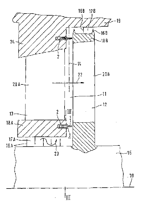
图1在纵剖面内表示一未详细示出的透平机械,例如燃气轮机或汽轮机的局部。透平机械有透平轴15,它沿旋转轴线16延伸。多个沿轴向彼此隔开距离可旋转并沿周向并列布置的部件12(工作叶片12)与透平轴15连接。沿周向并列设置的多个动叶片12构成一个动叶片组(动叶片栅,动叶片环),在这里为了看得清楚起见只表示了其中之一。每个工作叶片12基本上垂直于透平轴15定向并有一背对透平轴15的围带18B。围带18B与透平机械的外壳19相邻并例如有两个朝外壳19方向的密封齿16B。也可以采用更多或较少的密封齿16B。在外壳19上同样设一朝工作叶片12方向的密封齿16B。在围带18B与透平轴15之间,工作叶片12有一叶型区20B。在两个沿周向彼此隔开的工作叶片12之间,通过互相相邻的叶型区20B构成用于工作流体流动22的未详细表示的通流口,工作流体用于驱动工作叶片12并因而使透平轴15旋转。相对于工作流体的流动22方向,在工作叶片12的上游设有固定不动的部件13,即带多个导向叶片13的导向叶片装置,它与外壳19连接。表示在纵剖面内的导向叶片13同样有一围带18A,它与透平轴15相邻。在围带18A与外壳19之间,导向叶片13同样有叶型区20A,它用于使工作流体的流动22转向。在围带18A与透平轴15之间形成一径向间隙17A。类似地在外壳19与工作叶片12的围带18B之间形成一径向间隙17B。基本上垂直于旋转轴线10延伸的密封齿16A伸入径向间隙17A。密封齿16A与透平轴15和导向叶片13的围带18A交替地连接。FIG. 1 shows a detail of a turbomachine, for example a gas or steam turbine, not shown in detail, in longitudinal section. The turbomachine has a
在未详细表示的透平机械运行期间,各有一泄漏流23通过径向间隙17A和17B流动,泄漏流23是从工作流体的流动22中分流的。此外,在导向叶片13与工作叶片12之间,在各围带18B和18A所在区内由于工作叶片12与导向叶片13的轴向间隔而形成一轴向间隙11。轴向间隙11基本上沿伸展方向14定向,在这里伸展方向14垂直于旋转轴线10。在轴向间隙11内设密封装置1,它有密封件2。密封件2处于一个围绕着透平轴15制在导向叶片13内的圆环形密封环4上(见图3)。在导向叶片13的围带18A内以及在导向叶片13的根部24各设一密封件2,根部24与工作叶片12的围带18B彼此相对。每个密封件2包括许多刷毛3。刷毛3从导向叶片13基本上平行于旋转轴线10朝工作叶片12的方向延伸。根据密封件2的设计,刷毛3可一直伸到工作叶片12上,与它们接触或与之有一小的距离。通过刷毛3构成一密封环4,它几乎完全封闭了轴向间隙11。由此达到特别高效地密封轴向间隙11,并因而也密封了在其上游或在其下游的径向间隙17A、17B。其结果是明显减少泄漏流23,所以工作流体的流动22几乎完全经叶型区20A、20B导引。During operation of the turbomachine, not shown in detail, a
图2同样在未详细示出的透平机械的纵剖面内表示了一个局部。相同的附图标记有如图1中同样的意义。此密封件2与图1所示密封件2的区别在于,它相对于旋转轴线10倾斜一个约15°至20°,优选地约8°的轴向角α。因此,当密封件2的刷毛3与工作叶片12接触时,刷毛沿一共同的方向弯曲并因而实现轴向间隙11特别有效的密封。FIG. 2 likewise shows a detail in a longitudinal section of a turbomachine, not shown in detail. The same reference signs have the same meanings as in FIG. 1 . This
图3中示出图1所示透平轴15以及导向叶片13的围带18A的横截面。围带18A通过分界缝21分成两个对称的半部,其中每个半部由各相关导向叶片13的许多部分围带(图中未表示)构成。同样有可能的是将围带18A分成若干分段,例如八个45°分段。刷毛3汇合成一密封环4,它同样由可在分界缝21处彼此分开的两个对称的部分组成。采用密封件2即密封环4这种可分的设计,可使之例如在透平机械上进行维护工作或修理工作时便于检查或更换。FIG. 3 shows a cross section through the
本发明的特征在于刷状密封件,它尤其可伸入透平机械的旋转部件与固定部件之间的轴向间隙内,并因而保证轴向间隙的高效密封。因此,尤其当其应用于汽轮机内时,会提高汽轮机的效率,因为可明显减小通过轴向间隙的蒸汽泄漏流量,以及通过设在该轴向间隙上游或下游并且在流动上与之相连通的径向间隙的蒸汽泄漏流量。The invention is characterized by a brush-shaped seal which can in particular protrude into the axial gap between the rotating part and the stationary part of the turbomachine and thus ensures efficient sealing of the axial gap. Therefore, especially when it is used in a steam turbine, the efficiency of the steam turbine will be improved, because the steam leakage flow through the axial gap can be significantly reduced, and by being located upstream or downstream of the axial gap and in flow communication with it The steam leakage flow rate of the radial clearance.
Claims (12)
Applications Claiming Priority (2)
| Application Number | Priority Date | Filing Date | Title |
|---|---|---|---|
| DE19807029 | 1998-02-19 | ||
| DE19807029.2 | 1998-02-19 |
Publications (2)
| Publication Number | Publication Date |
|---|---|
| CN1292061A CN1292061A (en) | 2001-04-18 |
| CN1119503C true CN1119503C (en) | 2003-08-27 |
Family
ID=7858323
Family Applications (1)
| Application Number | Title | Priority Date | Filing Date |
|---|---|---|---|
| CN99803486A Expired - Fee Related CN1119503C (en) | 1998-02-19 | 1999-02-11 | Sealing device and use of sealing device |
Country Status (6)
| Country | Link |
|---|---|
| EP (1) | EP1056931B1 (en) |
| JP (1) | JP4224210B2 (en) |
| KR (1) | KR20010041102A (en) |
| CN (1) | CN1119503C (en) |
| DE (1) | DE59903021D1 (en) |
| WO (1) | WO1999042704A1 (en) |
Families Citing this family (17)
| Publication number | Priority date | Publication date | Assignee | Title |
|---|---|---|---|---|
| US6887038B2 (en) * | 2003-09-02 | 2005-05-03 | General Electric Company | Methods and apparatus to facilitate sealing between rotating turbine shafts |
| DE102005042272A1 (en) * | 2005-09-06 | 2007-03-08 | Mtu Aero Engines Gmbh | Turbomachine and sealing element for a turbomachine |
| US20070132190A1 (en) * | 2005-12-12 | 2007-06-14 | Charles Trabert | Axial dynamic brush seal |
| DE102007010378A1 (en) * | 2007-03-03 | 2008-09-04 | Mtu Aero Engines Gmbh | Sealing element for sealing gap between stator and rotor of axial flow machine is sealing brush that is essentially axis parallel to flow machine that seals relative to counter running surface protruding from rotor |
| DE102010026336A1 (en) * | 2010-07-07 | 2012-01-12 | Siemens Aktiengesellschaft | A shaft sealing apparatus |
| US8794918B2 (en) | 2011-01-07 | 2014-08-05 | General Electric Company | System for adjusting brush seal segments in turbomachine |
| US8777563B2 (en) * | 2011-01-31 | 2014-07-15 | General Electric Company | Axial brush seal |
| US9255486B2 (en) | 2011-03-28 | 2016-02-09 | General Electric Company | Rotating brush seal |
| US9121297B2 (en) | 2011-03-28 | 2015-09-01 | General Electric Company | Rotating brush seal |
| FR2974841B1 (en) * | 2011-05-04 | 2013-06-07 | Snecma | SEALING DEVICE FOR TURBINE MACHINE TURBINE DISPENSER |
| FR3010462B1 (en) * | 2013-09-11 | 2021-10-08 | Snecma | ANGULAR SECTOR OF RECTIFIER FOR TURBOMACHINE COMPRESSOR WITH A BRUSH SEAL |
| DE102013220276A1 (en) | 2013-10-08 | 2015-04-09 | MTU Aero Engines AG | flow machine |
| US10041367B2 (en) * | 2013-12-12 | 2018-08-07 | General Electric Company | Axially faced seal system |
| DE102016211280A1 (en) * | 2016-06-23 | 2017-12-28 | Siemens Aktiengesellschaft | steam turbine |
| CN106194279A (en) * | 2016-08-27 | 2016-12-07 | 朱艳君 | The axially mounted brush steam seal of steam turbine |
| DE102022200369A1 (en) * | 2022-01-14 | 2023-07-20 | Siemens Energy Global GmbH & Co. KG | Lightweight shovel tip and manufacturing process |
| CN114635757B (en) * | 2022-02-23 | 2023-12-12 | 潍柴动力股份有限公司 | Rotor sealing device |
Citations (2)
| Publication number | Priority date | Publication date | Assignee | Title |
|---|---|---|---|---|
| EP0169394A1 (en) * | 1984-07-07 | 1986-01-29 | Mtu Motoren- Und Turbinen-Union MàNchen Gmbh | Sealing between two machine parts |
| DE19519322A1 (en) * | 1995-05-26 | 1996-11-28 | Klein Schanzlin & Becker Ag | Seal between impeller and casing wall of centrifugal pump |
Family Cites Families (5)
| Publication number | Priority date | Publication date | Assignee | Title |
|---|---|---|---|---|
| AT33252B (en) | 1907-06-22 | 1908-06-10 | Sebastian Ziani De Ferranti | Brush seal for longitudinally moving or rotating machine parts. |
| GB2212228B (en) | 1987-11-13 | 1991-08-07 | Rolls Royce Plc | Enhanced performance brush seals |
| GB9020317D0 (en) | 1990-09-18 | 1990-10-31 | Cross Mfg Co | Sealing devices |
| FR2690493B1 (en) | 1992-04-23 | 1996-10-25 | Snecma | BRUSHED ANNULAR JOINT. |
| DE4304805A1 (en) | 1993-02-17 | 1994-08-18 | Abb Patent Gmbh | Device for contactless sealing between rooms of different pressures |
-
1999
- 1999-02-11 DE DE59903021T patent/DE59903021D1/en not_active Expired - Lifetime
- 1999-02-11 KR KR1020007009143A patent/KR20010041102A/en not_active Withdrawn
- 1999-02-11 JP JP2000532620A patent/JP4224210B2/en not_active Expired - Fee Related
- 1999-02-11 EP EP99914414A patent/EP1056931B1/en not_active Expired - Lifetime
- 1999-02-11 CN CN99803486A patent/CN1119503C/en not_active Expired - Fee Related
- 1999-02-11 WO PCT/DE1999/000389 patent/WO1999042704A1/en not_active Ceased
Patent Citations (2)
| Publication number | Priority date | Publication date | Assignee | Title |
|---|---|---|---|---|
| EP0169394A1 (en) * | 1984-07-07 | 1986-01-29 | Mtu Motoren- Und Turbinen-Union MàNchen Gmbh | Sealing between two machine parts |
| DE19519322A1 (en) * | 1995-05-26 | 1996-11-28 | Klein Schanzlin & Becker Ag | Seal between impeller and casing wall of centrifugal pump |
Also Published As
| Publication number | Publication date |
|---|---|
| JP2002504651A (en) | 2002-02-12 |
| EP1056931A1 (en) | 2000-12-06 |
| JP4224210B2 (en) | 2009-02-12 |
| EP1056931B1 (en) | 2002-10-09 |
| CN1292061A (en) | 2001-04-18 |
| WO1999042704A1 (en) | 1999-08-26 |
| DE59903021D1 (en) | 2002-11-14 |
| KR20010041102A (en) | 2001-05-15 |
Similar Documents
| Publication | Publication Date | Title |
|---|---|---|
| CN1119503C (en) | Sealing device and use of sealing device | |
| US7032903B1 (en) | Brush-seal designs for turbines and similar rotary apparatus | |
| US6027121A (en) | Combined brush/labyrinth seal for rotary machines | |
| US20120230818A1 (en) | Airfoil and corresponding guide vane, blade, gas turbine and turbomachine | |
| CN100350134C (en) | Method and apparatus to facilitate sealing within turbines | |
| AU784434B2 (en) | Improved brush-seal designs for turbines and similar rotary apparatus | |
| US6394459B1 (en) | Multi-clearance labyrinth seal design and related process | |
| KR100854193B1 (en) | Seal and steam gland | |
| KR102283730B1 (en) | A rotary machine secondary sealing assembly and method of assembling the same | |
| CN1211668A (en) | Anti-lag brush seal | |
| CN100554648C (en) | End face clearance seal and its improvement of the static sealing strip section at the top of the turbine blade | |
| US8561997B2 (en) | Adverse pressure gradient seal mechanism | |
| EP2894377B1 (en) | Turbo-engine | |
| CN104763476B (en) | Steam turbine and its assemble method | |
| US6761530B1 (en) | Method and apparatus to facilitate reducing turbine packing leakage losses | |
| CN1807846A (en) | Grouped reaction nozzle tip shrouds with integrated seals | |
| US6571470B1 (en) | Method of retrofitting seals in a gas turbine | |
| JP2015121217A (en) | Axial face seal system | |
| CN115163213A (en) | Rotary power generation equipment with isolation steam seal structure | |
| EP2055896A1 (en) | Bucket for a turbine of a thermal power plant having a foot section | |
| HK1107587B (en) | Improved brush-seal designs for turbines and similar rotary apparatus |
Legal Events
| Date | Code | Title | Description |
|---|---|---|---|
| C06 | Publication | ||
| PB01 | Publication | ||
| C10 | Entry into substantive examination | ||
| SE01 | Entry into force of request for substantive examination | ||
| C14 | Grant of patent or utility model | ||
| GR01 | Patent grant | ||
| C17 | Cessation of patent right | ||
| CF01 | Termination of patent right due to non-payment of annual fee |
Granted publication date: 20030827 Termination date: 20140211 |