EP1056680B1 - Vacuum gripping apparatus - Google Patents
Vacuum gripping apparatus Download PDFInfo
- Publication number
- EP1056680B1 EP1056680B1 EP99954015A EP99954015A EP1056680B1 EP 1056680 B1 EP1056680 B1 EP 1056680B1 EP 99954015 A EP99954015 A EP 99954015A EP 99954015 A EP99954015 A EP 99954015A EP 1056680 B1 EP1056680 B1 EP 1056680B1
- Authority
- EP
- European Patent Office
- Prior art keywords
- suction plate
- gripping apparatus
- vacuum gripping
- vacuum
- outer circumference
- Prior art date
- Legal status (The legal status is an assumption and is not a legal conclusion. Google has not performed a legal analysis and makes no representation as to the accuracy of the status listed.)
- Expired - Lifetime
Links
Images


Classifications
-
- B—PERFORMING OPERATIONS; TRANSPORTING
- B66—HOISTING; LIFTING; HAULING
- B66C—CRANES; LOAD-ENGAGING ELEMENTS OR DEVICES FOR CRANES, CAPSTANS, WINCHES, OR TACKLES
- B66C1/00—Load-engaging elements or devices attached to lifting or lowering gear of cranes or adapted for connection therewith for transmitting lifting forces to articles or groups of articles
- B66C1/02—Load-engaging elements or devices attached to lifting or lowering gear of cranes or adapted for connection therewith for transmitting lifting forces to articles or groups of articles by suction means
- B66C1/0293—Single lifting units; Only one suction cup
-
- B—PERFORMING OPERATIONS; TRANSPORTING
- B66—HOISTING; LIFTING; HAULING
- B66C—CRANES; LOAD-ENGAGING ELEMENTS OR DEVICES FOR CRANES, CAPSTANS, WINCHES, OR TACKLES
- B66C1/00—Load-engaging elements or devices attached to lifting or lowering gear of cranes or adapted for connection therewith for transmitting lifting forces to articles or groups of articles
- B66C1/02—Load-engaging elements or devices attached to lifting or lowering gear of cranes or adapted for connection therewith for transmitting lifting forces to articles or groups of articles by suction means
- B66C1/0231—Special lip configurations
-
- B—PERFORMING OPERATIONS; TRANSPORTING
- B66—HOISTING; LIFTING; HAULING
- B66C—CRANES; LOAD-ENGAGING ELEMENTS OR DEVICES FOR CRANES, CAPSTANS, WINCHES, OR TACKLES
- B66C1/00—Load-engaging elements or devices attached to lifting or lowering gear of cranes or adapted for connection therewith for transmitting lifting forces to articles or groups of articles
- B66C1/02—Load-engaging elements or devices attached to lifting or lowering gear of cranes or adapted for connection therewith for transmitting lifting forces to articles or groups of articles by suction means
- B66C1/0287—Other shapes, e.g. triangular or oval
Definitions
- the invention relates to a vacuum gripping apparatus for moving roll-like loads, the loads being piled on top of each other and resting on their even end faces and the vacuum gripping apparatus comprising a suction plate to be arranged against the end face of a load.
- the described vacuum gripping apparatus can be used for lifting and moving rolls of reeled paper, metal, plastic or laminate, for example. It can also be used for moving cylindrical hollow pieces having even end faces.
- the vacuum gripping apparatus can be liftably and lowerably suspended to a lifting device of a crane, although other lifting apparatuses can also be used.
- a conventional prior art vacuum gripping apparatus is described in publication DE-U 84 35 161, corresponding to the preamble of claim 1.
- the apparatus comprises an even suction plate in the lower portion, with several concentric ring seals arranged at a distance onto the underside of the suction plate to provide the gripping surface.
- the ring seals form vacuum spaces, separated from one another, between the suction plate and the load to be transported.
- the ring seals do not have to be circular but they may have any other form, too; they may be elliptical or angular, for example, as long as they form a closed ring. It is not absolutely necessary that the ring seals are within each other either. It is also possible to arrange several vacuum spaces formed at a distance from one another.
- the vacuum spaces are connected through holes provided in the suction plate and a connecting conduit comprising a valve to a vacuum source comprising a vacuum generator.
- a connecting conduit comprising a valve to a vacuum source comprising a vacuum generator.
- the vacuum gripping apparatus is lowered onto the load and the valve device is set in a suction position, thereby creating a connection between the vacuum source and the vacuum space or spaces.
- the valve device is set in a suction position, thereby creating a connection between the vacuum source and the vacuum space or spaces.
- several valves can also be arranged, the valves being arranged in such a way that the connection to the vacuum source opens only when the vacuum space in question is fully covered by the load gripping surface.
- valve device After the load has been lifted or deposited, the valve device is switched from the suction position back to the ventilation position. The vacuum gripping apparatus can then be lifted with the lifting device from the lowered load.
- the above described vacuum gripping apparatus comprises a vacuum container above the suction plate, the container and the suction plate both having a circular horizontal cross-sectional form.
- the upper surface of the container provides a mounting surface for arranging various kinds of aggregates and devices that are necessary for the use of a vacuum lifting apparatus.
- Roll stacks can be more than 12m high, so due to reasons of space, they must be arranged extremely close to each other.
- the minimum free distance between two roll stacks can be 100mm, for example.
- the apparatus may not be greater than the maximum diameter of the roll to be received.
- An object of the present invention is to solve the last one of the above problems.
- the object is achieved with a vacuum gripping apparatus according to the invention specifed in claim 1, in which the outer circumference of the suction plate is provided with corner portions, the side edges connecting the corners of the portions being curved inward, such that the outer circumference of the suction plate determines the maximum lateral dimensions of the structure above the suction plate.
- the invention is based on the fact that the minimum distance between a roll stack and the surrounding roll stacks is always at one point only, i.e. on the lines connecting the centers of the roll stacks. Between the connecting lines the distance is longer, free surfaces being thus formed.
- the invention is based on the idea of utilizing the surface areas, in the suction plate in particular, without increasing the risk of collision with adjacent roll stacks.
- the only restriction on the upper structure is that it is not to extend beyond the edges of the suction plate in lateral direction.
- the upper structure can thus be a prior art structure, for example, or like the one presented in the solution of the above mentioned Fl Patent.
- the most essential objective is therefore to increase suction power by maximizing the surface of the suction plate.
- the number and form of the corner portions in the suction plate can be adjusted according to a particular arrangement of roll stacks in storage.
- roll stacks are arranged in such a way that the centers of the roll stacks form the corners of equilateral triangles.
- the appropriate form for the outer circumference of the suction plate of the invention is a regular polygon, preferably a hexagon. In other roll stack arrangements different polygons optimally utilising the available space are naturally possible.
- a particularly large increase in surface is obtained by curving inward the side edges connecting the corners of the corner portions, most preferably into an arch form.
- this is appropriately achieved when the arch-formed side edges are concentric with adjacent roll stacks in such a way the side edges are at their entire length at the allowed minimum distance from the adjacent roll stacks, the free space thus being optimally used.
- the edges should preferably be bevelled.
- the outermost seal edge of the seal arrangement on the underside of the suction plate should follow the form of the outer circumference of the suction plate as close to the edge of the outer circumference as possible.
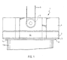
- a lower portion of a vacuum gripping apparatus 1 shown in Figure 1 is provided with a vacuum container 2 connected to a vacuum generator not shown here.
- a suction plate 3 closes the underside of the vacuum container 2, a casing 4 being arranged above the vacuum container 2, the casing enclosing aggregates and devices, such as the vacuum generator, an emergency vacuum generator, batteries, electric switches, etc., associated with the vacuum gripping apparatus 1 and not described in detail in this context.
- the casing 4 there are pivoted guiding rolls 5 via which the vacuum gripping apparatus is liftably and lowerably suspended on ropes 6 of a lifting apparatus not described here in detail.
- the underside of the suction plate 3 is provided with seal rings 7 to 11 arranged one inside the other, the outermost seal ring 11 following the form of the outer circumference 12 of the suction plate 3, close to the outer circumference 12. Together with a top surface 14 of a paper roll 13 the seal rings 7 to 11 form vacuum spaces 15 to 18 for lifting the paper roll 13 by applying a vacuum generated into the spaces.
- the suction plate 3 is formed here as a substantially regular hexagon comprising comer portions 19 provided with bevels 20 to avoid sharp corners. Side edges 21 starting at the edges of the bevels 20 are inward concave, and to arrange the side edges with adjacent paper roll stacks 22 and 23 ( Figures 3 and 4), the side edges 21 are arranged concentric with the adjacent paper roll stacks 22 and 23.
- the suction plate 3 is thereby provided with the greatest surface possible, maintaining at the same time the allowed distance between the side edges 21 and the covering surfaces of the paper roll stacks 22 and 23, particularly in the case shown in Figure 3.
- the vacuum container 2 and the casing 4 can be made into any form, provided that their contours do not extend beyond the outer circumference 12 of the suction plate 3 in lateral direction and that a vacuum can be provided into all vacuum spaces 15 to 18 when needed.
- the described vacuum container 2 and casing 4 can be imagined to have a horizontal cross-section substantially of the same form as the suction plate 3.
- the vacuum gripping apparatus 1 is driven between paper roll stacks 22 and 23, respectively, the suction plate forming the outer contours of the vacuum gripping apparatus.
- the paper roll stacks 22 and 23 are arranged in such a way that their midpoints form the corners of an equilateral triangle, a maximum packing density being thereby obtained.
- the vacuum gripping apparatus 1 being provided with the suction plate 3 of the invention, the suction plate is able to lift rolls of considerably different sizes because, on one hand, it fits between paper roll stacks 22 of a smaller diameter and, on the other hand, it has sufficient suction power enabling rolls in paper roll stacks 23 of considerably larger diameter to be lifted.
Applications Claiming Priority (3)
| Application Number | Priority Date | Filing Date | Title |
|---|---|---|---|
| FI982299 | 1998-10-23 | ||
| FI982299A FI104552B (fi) | 1998-10-23 | 1998-10-23 | Alipainetarrain |
| PCT/FI1999/000882 WO2000024665A1 (en) | 1998-10-23 | 1999-10-22 | Vacuum gripping apparatus |
Publications (2)
| Publication Number | Publication Date |
|---|---|
| EP1056680A1 EP1056680A1 (en) | 2000-12-06 |
| EP1056680B1 true EP1056680B1 (en) | 2003-07-16 |
Family
ID=8552771
Family Applications (1)
| Application Number | Title | Priority Date | Filing Date |
|---|---|---|---|
| EP99954015A Expired - Lifetime EP1056680B1 (en) | 1998-10-23 | 1999-10-22 | Vacuum gripping apparatus |
Country Status (11)
| Country | Link |
|---|---|
| US (1) | US6375240B1 (fi) |
| EP (1) | EP1056680B1 (fi) |
| JP (1) | JP2002528360A (fi) |
| AT (1) | ATE245121T1 (fi) |
| CA (1) | CA2312388C (fi) |
| DE (1) | DE69909595T2 (fi) |
| DK (1) | DK1056680T3 (fi) |
| ES (1) | ES2203200T3 (fi) |
| FI (1) | FI104552B (fi) |
| PT (1) | PT1056680E (fi) |
| WO (1) | WO2000024665A1 (fi) |
Families Citing this family (7)
| Publication number | Priority date | Publication date | Assignee | Title |
|---|---|---|---|---|
| US7520872B2 (en) * | 2002-09-13 | 2009-04-21 | Neogen Technologies, Inc. | Closed wound drainage system |
| US6979324B2 (en) * | 2002-09-13 | 2005-12-27 | Neogen Technologies, Inc. | Closed wound drainage system |
| DE102005009315A1 (de) * | 2005-02-18 | 2006-08-24 | Alfred Kärcher Gmbh & Co. Kg | Befestigungseinrichtung |
| US8083712B2 (en) * | 2007-03-20 | 2011-12-27 | Neogen Technologies, Inc. | Flat-hose assembly for wound drainage system |
| ES2361726T3 (es) * | 2007-06-13 | 2011-06-21 | Frattini-Tech Ag | Dispositivo de agarre y manejo de recipientes metálicos. |
| US9011393B2 (en) * | 2009-12-18 | 2015-04-21 | Kci Licensing, Inc. | Systems, methods, and devices for restoring lymphatic flow associated with a subcutaneous defect in a patients body |
| CN111847209A (zh) * | 2020-07-15 | 2020-10-30 | 浙江农林大学暨阳学院 | 一种数字化制造用真空吸盘装置 |
Family Cites Families (11)
| Publication number | Priority date | Publication date | Assignee | Title |
|---|---|---|---|---|
| US1505626A (en) * | 1922-11-14 | 1924-08-19 | Saint Gobain | Suction device for lifting and transporting articles having any kind of surface |
| US3376061A (en) * | 1966-02-03 | 1968-04-02 | Hyster Co | Suction load-handling apparatus |
| US3758144A (en) * | 1972-01-06 | 1973-09-11 | H Dalglish | Vacuum center lift |
| US3833251A (en) * | 1972-10-06 | 1974-09-03 | Aerovac Corp | Longitudinally stiffened flexible lifter for arcuate objects |
| US3926466A (en) | 1973-10-01 | 1975-12-16 | Ethyl Corp | Apparatus for handling rolls |
| DE8435161U1 (de) | 1984-11-30 | 1985-05-23 | Bartholomy & Co, 516O Düren | Vakuumheber |
| US4925225A (en) * | 1989-06-19 | 1990-05-15 | Dost Incorporated | Vacuum lifting device for handling sheet material |
| DE9013528U1 (fi) * | 1990-09-26 | 1991-04-11 | Bartholomy & Co, 516O Dueren, De | |
| DE9015109U1 (fi) | 1990-11-02 | 1991-01-10 | Bartholomy & Co, 516O Dueren, De | |
| DE9101063U1 (fi) | 1991-01-31 | 1991-04-18 | Rico-Maschinenbau Max Appel Kg, 7080 Aalen, De | |
| FI971382A (fi) | 1997-04-03 | 1998-10-04 | Kci Kone Cranes Int Oy | Menetelmä taakan nostamiseksi alipainetarraimella |
-
1998
- 1998-10-23 FI FI982299A patent/FI104552B/fi not_active IP Right Cessation
-
1999
- 1999-10-22 DK DK99954015T patent/DK1056680T3/da active
- 1999-10-22 EP EP99954015A patent/EP1056680B1/en not_active Expired - Lifetime
- 1999-10-22 DE DE69909595T patent/DE69909595T2/de not_active Expired - Lifetime
- 1999-10-22 AT AT99954015T patent/ATE245121T1/de active
- 1999-10-22 JP JP2000578241A patent/JP2002528360A/ja active Pending
- 1999-10-22 WO PCT/FI1999/000882 patent/WO2000024665A1/en active IP Right Grant
- 1999-10-22 CA CA002312388A patent/CA2312388C/en not_active Expired - Fee Related
- 1999-10-22 PT PT99954015T patent/PT1056680E/pt unknown
- 1999-10-22 ES ES99954015T patent/ES2203200T3/es not_active Expired - Lifetime
- 1999-10-22 US US09/582,331 patent/US6375240B1/en not_active Expired - Fee Related
Also Published As
| Publication number | Publication date |
|---|---|
| WO2000024665A1 (en) | 2000-05-04 |
| FI982299A0 (fi) | 1998-10-23 |
| FI104552B (fi) | 2000-02-29 |
| JP2002528360A (ja) | 2002-09-03 |
| ATE245121T1 (de) | 2003-08-15 |
| PT1056680E (pt) | 2003-11-28 |
| EP1056680A1 (en) | 2000-12-06 |
| US6375240B1 (en) | 2002-04-23 |
| DE69909595D1 (de) | 2003-08-21 |
| CA2312388A1 (en) | 2000-05-04 |
| CA2312388C (en) | 2009-12-29 |
| DK1056680T3 (da) | 2003-10-27 |
| DE69909595T2 (de) | 2004-05-27 |
| ES2203200T3 (es) | 2004-04-01 |
Similar Documents
| Publication | Publication Date | Title |
|---|---|---|
| EP1056680B1 (en) | Vacuum gripping apparatus | |
| GB2342946A (en) | Method and apparatus for the offshore installation of multi-ton packages such as deck packages and jackets | |
| ATE420998T1 (de) | Verfahren und vorrichtung zum installieren von vorgefertigten deckkonstruktionen auf offshore hubfundamenten | |
| CA2217548A1 (en) | Counterweight handling system for ring-supported cranes | |
| CA2265684A1 (en) | A can with a cover provided with a pull ring | |
| CN204597312U (zh) | 箱式变电站 | |
| CN215666631U (zh) | 一种风力发电机组轮毂的吊装工具 | |
| US5600686A (en) | Method for replacing a component located in the interior of a containment of a nuclear reactor | |
| FI94615C (fi) | Tyhjönostin | |
| IT1262591B (it) | Impianto di smistamento, formazione e allontanamento di pile, di piastrelle ceramiche multiformato. | |
| CN216836730U (zh) | 一种用于叠合板吊装的插销式下吊梁 | |
| KR102023707B1 (ko) | 크레인 | |
| CN214827386U (zh) | 一种浅圆仓便拆式可调节出库环保减损装置 | |
| CN215622100U (zh) | 一种建筑工程用材料运输装置 | |
| CN217417891U (zh) | 一种适用于竖井维修施工用吊装工具 | |
| CN212893544U (zh) | 一种用于限制空间内储罐安装用转运吊装装置 | |
| CN214298955U (zh) | 预制梁板锐角保护装置 | |
| CN211895162U (zh) | 一种建筑水泥砌块装卸装置 | |
| CN219009269U (zh) | 一种电芯堆叠装置 | |
| CN114583633B (zh) | 可移动杠杆式电缆轴支架施工方法 | |
| CN211594741U (zh) | 钢卷加工生产线用行车吊运装置 | |
| CN207234217U (zh) | 一种太阳能变电站 | |
| CN115288202A (zh) | 一种便于更换的加强型水泥盖板 | |
| JPH074058A (ja) | 高層建物のpc壁版の揚重方法及び揚重装置 | |
| JP2596283B2 (ja) | 全方位型立体構台 |
Legal Events
| Date | Code | Title | Description |
|---|---|---|---|
| PUAI | Public reference made under article 153(3) epc to a published international application that has entered the european phase |
Free format text: ORIGINAL CODE: 0009012 |
|
| 17P | Request for examination filed |
Effective date: 20000616 |
|
| AK | Designated contracting states |
Kind code of ref document: A1 Designated state(s): AT BE CH CY DE DK ES FI FR GB GR IE IT LI LU MC NL PT SE |
|
| 17Q | First examination report despatched |
Effective date: 20020402 |
|
| GRAH | Despatch of communication of intention to grant a patent |
Free format text: ORIGINAL CODE: EPIDOS IGRA |
|
| GRAH | Despatch of communication of intention to grant a patent |
Free format text: ORIGINAL CODE: EPIDOS IGRA |
|
| GRAA | (expected) grant |
Free format text: ORIGINAL CODE: 0009210 |
|
| RAP1 | Party data changed (applicant data changed or rights of an application transferred) |
Owner name: KCI KONECRANES PLC |
|
| AK | Designated contracting states |
Designated state(s): AT BE CH CY DE DK ES FI FR GB GR IE IT LI LU MC NL PT SE |
|
| PG25 | Lapsed in a contracting state [announced via postgrant information from national office to epo] |
Ref country code: FI Free format text: LAPSE BECAUSE OF FAILURE TO SUBMIT A TRANSLATION OF THE DESCRIPTION OR TO PAY THE FEE WITHIN THE PRESCRIBED TIME-LIMIT Effective date: 20030716 |
|
| REG | Reference to a national code |
Ref country code: GB Ref legal event code: FG4D |
|
| REG | Reference to a national code |
Ref country code: CH Ref legal event code: EP |
|
| REG | Reference to a national code |
Ref country code: IE Ref legal event code: FG4D |
|
| REF | Corresponds to: |
Ref document number: 69909595 Country of ref document: DE Date of ref document: 20030821 Kind code of ref document: P |
|
| REG | Reference to a national code |
Ref country code: CH Ref legal event code: NV Representative=s name: WERNER BRUDERER PATENTANWALT |
|
| PG25 | Lapsed in a contracting state [announced via postgrant information from national office to epo] |
Ref country code: LU Free format text: LAPSE BECAUSE OF NON-PAYMENT OF DUE FEES Effective date: 20031022 Ref country code: CY Free format text: LAPSE BECAUSE OF FAILURE TO SUBMIT A TRANSLATION OF THE DESCRIPTION OR TO PAY THE FEE WITHIN THE PRESCRIBED TIME-LIMIT Effective date: 20031022 |
|
| PG25 | Lapsed in a contracting state [announced via postgrant information from national office to epo] |
Ref country code: MC Free format text: LAPSE BECAUSE OF NON-PAYMENT OF DUE FEES Effective date: 20031031 |
|
| REG | Reference to a national code |
Ref country code: SE Ref legal event code: TRGR |
|
| REG | Reference to a national code |
Ref country code: GR Ref legal event code: EP Ref document number: 20030403989 Country of ref document: GR |
|
| REG | Reference to a national code |
Ref country code: ES Ref legal event code: FG2A Ref document number: 2203200 Country of ref document: ES Kind code of ref document: T3 |
|
| ET | Fr: translation filed | ||
| PLBE | No opposition filed within time limit |
Free format text: ORIGINAL CODE: 0009261 |
|
| STAA | Information on the status of an ep patent application or granted ep patent |
Free format text: STATUS: NO OPPOSITION FILED WITHIN TIME LIMIT |
|
| 26N | No opposition filed |
Effective date: 20040419 |
|
| REG | Reference to a national code |
Ref country code: CH Ref legal event code: NV Representative=s name: FREI PATENTANWALTSBUERO AG |
|
| PGFP | Annual fee paid to national office [announced via postgrant information from national office to epo] |
Ref country code: DK Payment date: 20121025 Year of fee payment: 14 |
|
| PGFP | Annual fee paid to national office [announced via postgrant information from national office to epo] |
Ref country code: FR Payment date: 20121205 Year of fee payment: 14 Ref country code: BE Payment date: 20121029 Year of fee payment: 14 Ref country code: CH Payment date: 20121017 Year of fee payment: 14 Ref country code: IE Payment date: 20121017 Year of fee payment: 14 |
|
| PGFP | Annual fee paid to national office [announced via postgrant information from national office to epo] |
Ref country code: GB Payment date: 20121024 Year of fee payment: 14 Ref country code: PT Payment date: 20120423 Year of fee payment: 14 Ref country code: IT Payment date: 20121025 Year of fee payment: 14 Ref country code: ES Payment date: 20121018 Year of fee payment: 14 Ref country code: GR Payment date: 20121029 Year of fee payment: 14 Ref country code: SE Payment date: 20121024 Year of fee payment: 14 |
|
| PGFP | Annual fee paid to national office [announced via postgrant information from national office to epo] |
Ref country code: NL Payment date: 20121024 Year of fee payment: 14 Ref country code: AT Payment date: 20121030 Year of fee payment: 14 |
|
| BERE | Be: lapsed |
Owner name: *KCI KONECRANES P.L.C. Effective date: 20131031 |
|
| REG | Reference to a national code |
Ref country code: PT Ref legal event code: MM4A Free format text: LAPSE DUE TO NON-PAYMENT OF FEES Effective date: 20140422 |
|
| REG | Reference to a national code |
Ref country code: NL Ref legal event code: V1 Effective date: 20140501 |
|
| REG | Reference to a national code |
Ref country code: DK Ref legal event code: EBP Effective date: 20131031 |
|
| REG | Reference to a national code |
Ref country code: CH Ref legal event code: PL |
|
| REG | Reference to a national code |
Ref country code: SE Ref legal event code: EUG |
|
| REG | Reference to a national code |
Ref country code: AT Ref legal event code: MM01 Ref document number: 245121 Country of ref document: AT Kind code of ref document: T Effective date: 20131022 |
|
| GBPC | Gb: european patent ceased through non-payment of renewal fee |
Effective date: 20131022 |
|
| REG | Reference to a national code |
Ref country code: GR Ref legal event code: ML Ref document number: 20030403989 Country of ref document: GR Effective date: 20140505 |
|
| REG | Reference to a national code |
Ref country code: IE Ref legal event code: MM4A |
|
| PG25 | Lapsed in a contracting state [announced via postgrant information from national office to epo] |
Ref country code: GB Free format text: LAPSE BECAUSE OF NON-PAYMENT OF DUE FEES Effective date: 20131022 Ref country code: LI Free format text: LAPSE BECAUSE OF NON-PAYMENT OF DUE FEES Effective date: 20131031 Ref country code: CH Free format text: LAPSE BECAUSE OF NON-PAYMENT OF DUE FEES Effective date: 20131031 |
|
| REG | Reference to a national code |
Ref country code: FR Ref legal event code: ST Effective date: 20140630 |
|
| PG25 | Lapsed in a contracting state [announced via postgrant information from national office to epo] |
Ref country code: FR Free format text: LAPSE BECAUSE OF NON-PAYMENT OF DUE FEES Effective date: 20131031 Ref country code: GR Free format text: LAPSE BECAUSE OF NON-PAYMENT OF DUE FEES Effective date: 20140505 Ref country code: AT Free format text: LAPSE BECAUSE OF NON-PAYMENT OF DUE FEES Effective date: 20131022 Ref country code: NL Free format text: LAPSE BECAUSE OF NON-PAYMENT OF DUE FEES Effective date: 20140501 Ref country code: SE Free format text: LAPSE BECAUSE OF NON-PAYMENT OF DUE FEES Effective date: 20131023 Ref country code: IT Free format text: LAPSE BECAUSE OF NON-PAYMENT OF DUE FEES Effective date: 20131022 Ref country code: PT Free format text: LAPSE BECAUSE OF NON-PAYMENT OF DUE FEES Effective date: 20140422 |
|
| PG25 | Lapsed in a contracting state [announced via postgrant information from national office to epo] |
Ref country code: BE Free format text: LAPSE BECAUSE OF NON-PAYMENT OF DUE FEES Effective date: 20131031 |
|
| PG25 | Lapsed in a contracting state [announced via postgrant information from national office to epo] |
Ref country code: IE Free format text: LAPSE BECAUSE OF NON-PAYMENT OF DUE FEES Effective date: 20131022 Ref country code: DK Free format text: LAPSE BECAUSE OF NON-PAYMENT OF DUE FEES Effective date: 20131031 |
|
| REG | Reference to a national code |
Ref country code: ES Ref legal event code: FD2A Effective date: 20150504 |
|
| PG25 | Lapsed in a contracting state [announced via postgrant information from national office to epo] |
Ref country code: ES Free format text: LAPSE BECAUSE OF NON-PAYMENT OF DUE FEES Effective date: 20131023 |
|
| PGFP | Annual fee paid to national office [announced via postgrant information from national office to epo] |
Ref country code: DE Payment date: 20151026 Year of fee payment: 17 |
|
| REG | Reference to a national code |
Ref country code: DE Ref legal event code: R082 Ref document number: 69909595 Country of ref document: DE Representative=s name: RUEGER ABEL PATENT- UND RECHTSANWAELTE, DE Ref country code: DE Ref legal event code: R082 Ref document number: 69909595 Country of ref document: DE Representative=s name: RUEGER, BARTHELT & ABEL, DE Ref country code: DE Ref legal event code: R081 Ref document number: 69909595 Country of ref document: DE Owner name: KONECRANES GLOBAL CORPORATION, FI Free format text: FORMER OWNER: KCI KONECRANES PLC, HYVINKAEAE, FI |
|
| REG | Reference to a national code |
Ref country code: DE Ref legal event code: R119 Ref document number: 69909595 Country of ref document: DE |
|
| PG25 | Lapsed in a contracting state [announced via postgrant information from national office to epo] |
Ref country code: DE Free format text: LAPSE BECAUSE OF NON-PAYMENT OF DUE FEES Effective date: 20170503 |