EP1056680B1 - Vacuum gripping apparatus - Google Patents
Vacuum gripping apparatus Download PDFInfo
- Publication number
- EP1056680B1 EP1056680B1 EP99954015A EP99954015A EP1056680B1 EP 1056680 B1 EP1056680 B1 EP 1056680B1 EP 99954015 A EP99954015 A EP 99954015A EP 99954015 A EP99954015 A EP 99954015A EP 1056680 B1 EP1056680 B1 EP 1056680B1
- Authority
- EP
- European Patent Office
- Prior art keywords
- suction plate
- gripping apparatus
- vacuum gripping
- vacuum
- outer circumference
- Prior art date
- Legal status (The legal status is an assumption and is not a legal conclusion. Google has not performed a legal analysis and makes no representation as to the accuracy of the status listed.)
- Expired - Lifetime
Links
Images


Classifications
-
- B—PERFORMING OPERATIONS; TRANSPORTING
- B66—HOISTING; LIFTING; HAULING
- B66C—CRANES; LOAD-ENGAGING ELEMENTS OR DEVICES FOR CRANES, CAPSTANS, WINCHES, OR TACKLES
- B66C1/00—Load-engaging elements or devices attached to lifting or lowering gear of cranes or adapted for connection therewith for transmitting lifting forces to articles or groups of articles
- B66C1/02—Load-engaging elements or devices attached to lifting or lowering gear of cranes or adapted for connection therewith for transmitting lifting forces to articles or groups of articles by suction means
- B66C1/0293—Single lifting units; Only one suction cup
-
- B—PERFORMING OPERATIONS; TRANSPORTING
- B66—HOISTING; LIFTING; HAULING
- B66C—CRANES; LOAD-ENGAGING ELEMENTS OR DEVICES FOR CRANES, CAPSTANS, WINCHES, OR TACKLES
- B66C1/00—Load-engaging elements or devices attached to lifting or lowering gear of cranes or adapted for connection therewith for transmitting lifting forces to articles or groups of articles
- B66C1/02—Load-engaging elements or devices attached to lifting or lowering gear of cranes or adapted for connection therewith for transmitting lifting forces to articles or groups of articles by suction means
- B66C1/0231—Special lip configurations
-
- B—PERFORMING OPERATIONS; TRANSPORTING
- B66—HOISTING; LIFTING; HAULING
- B66C—CRANES; LOAD-ENGAGING ELEMENTS OR DEVICES FOR CRANES, CAPSTANS, WINCHES, OR TACKLES
- B66C1/00—Load-engaging elements or devices attached to lifting or lowering gear of cranes or adapted for connection therewith for transmitting lifting forces to articles or groups of articles
- B66C1/02—Load-engaging elements or devices attached to lifting or lowering gear of cranes or adapted for connection therewith for transmitting lifting forces to articles or groups of articles by suction means
- B66C1/0287—Other shapes, e.g. triangular or oval
Landscapes
- Engineering & Computer Science (AREA)
- Mechanical Engineering (AREA)
- Physics & Mathematics (AREA)
- Geometry (AREA)
- Load-Engaging Elements For Cranes (AREA)
- Sheets, Magazines, And Separation Thereof (AREA)
- Manipulator (AREA)
- Valves And Accessory Devices For Braking Systems (AREA)
- Valve-Gear Or Valve Arrangements (AREA)
- Valve Device For Special Equipments (AREA)
- Carriers, Traveling Bodies, And Overhead Traveling Cranes (AREA)
- Auxiliary Devices For And Details Of Packaging Control (AREA)
- Crystals, And After-Treatments Of Crystals (AREA)
- Superconductors And Manufacturing Methods Therefor (AREA)
- Tents Or Canopies (AREA)
- Pens And Brushes (AREA)
- Vehicle Interior And Exterior Ornaments, Soundproofing, And Insulation (AREA)
Abstract
Description
- The invention relates to a vacuum gripping apparatus for moving roll-like loads, the loads being piled on top of each other and resting on their even end faces and the vacuum gripping apparatus comprising a suction plate to be arranged against the end face of a load.
- The described vacuum gripping apparatus can be used for lifting and moving rolls of reeled paper, metal, plastic or laminate, for example. It can also be used for moving cylindrical hollow pieces having even end faces. The vacuum gripping apparatus can be liftably and lowerably suspended to a lifting device of a crane, although other lifting apparatuses can also be used.
- A conventional prior art vacuum gripping apparatus is described in publication DE-U 84 35 161, corresponding to the preamble of
claim 1. The apparatus comprises an even suction plate in the lower portion, with several concentric ring seals arranged at a distance onto the underside of the suction plate to provide the gripping surface. When the suction plate is placed down onto the end face providing the gripping surface of the load, the ring seals form vacuum spaces, separated from one another, between the suction plate and the load to be transported. Naturally the ring seals do not have to be circular but they may have any other form, too; they may be elliptical or angular, for example, as long as they form a closed ring. It is not absolutely necessary that the ring seals are within each other either. It is also possible to arrange several vacuum spaces formed at a distance from one another. - The vacuum spaces are connected through holes provided in the suction plate and a connecting conduit comprising a valve to a vacuum source comprising a vacuum generator. When there is no load suspended from the vacuum gripping apparatus, the connection to the suction generator is cut off and the vacuum space or spaces are ventilated.
- To lift a load, the vacuum gripping apparatus is lowered onto the load and the valve device is set in a suction position, thereby creating a connection between the vacuum source and the vacuum space or spaces. If several vacuum spaces are used, several valves can also be arranged, the valves being arranged in such a way that the connection to the vacuum source opens only when the vacuum space in question is fully covered by the load gripping surface. When the vacuum space or spaces have been subjected to a sufficient vacuum in the lifting process, the load can be lifted or moved.
- After the load has been lifted or deposited, the valve device is switched from the suction position back to the ventilation position. The vacuum gripping apparatus can then be lifted with the lifting device from the lowered load.
- The above described vacuum gripping apparatus comprises a vacuum container above the suction plate, the container and the suction plate both having a circular horizontal cross-sectional form. The upper surface of the container provides a mounting surface for arranging various kinds of aggregates and devices that are necessary for the use of a vacuum lifting apparatus.
- Roll stacks can be more than 12m high, so due to reasons of space, they must be arranged extremely close to each other. For roll diameters up to 2500mm, the minimum free distance between two roll stacks can be 100mm, for example. To prevent the vacuum gripping apparatus from colliding with the roll stacks when the apparatus is driven into a cavity surrounded by the roll stacks, the apparatus may not be greater than the maximum diameter of the roll to be received.
- Various solutions have been presented to solve the problems of space thus arising in the mounting of the aggregates and other devices needed in the vacuum gripping apparatus. It has been suggested that separate aggregates would be removed from the vacuum gripping apparatus and arranged to the lifting apparatus. On the other hand, Fl Patent 94615 proposes that the mounting space in question would be formed into a hexagon, as this would allow optimal use of the space between the roll stacks without increasing the risk of collision with the roll stacks, thereby providing more mounting space for the aggregates.
- If it is necessary to store rolls of clearly different diameters (two different diameters, for example) into one and the same storage area, the most reasonable way to utilize the space is to store the rolls in a matrix format according to size. Current technology requires that the diameter of the vacuum gripping apparatus, and that of the suction plate in particular, must be selected according to the smaller (or the smallest) matrix. Depending on the weight of a roll, sufficient suction power ensuring safe lifting of rolls of a greater diameter cannot always be provided. On the other hand, a small suction diameter is not enough to support the end surface of looser rolls, and the form of the rolls cannot be maintained during the lifting.
- An object of the present invention is to solve the last one of the above problems. The object is achieved with a vacuum gripping apparatus according to the invention specifed in
claim 1, in which the outer circumference of the suction plate is provided with corner portions, the side edges connecting the corners of the portions being curved inward, such that the outer circumference of the suction plate determines the maximum lateral dimensions of the structure above the suction plate. - The invention, particularly as regards the suction plate, is based on the fact that the minimum distance between a roll stack and the surrounding roll stacks is always at one point only, i.e. on the lines connecting the centers of the roll stacks. Between the connecting lines the distance is longer, free surfaces being thus formed. The invention is based on the idea of utilizing the surface areas, in the suction plate in particular, without increasing the risk of collision with adjacent roll stacks. The only restriction on the upper structure is that it is not to extend beyond the edges of the suction plate in lateral direction. The upper structure can thus be a prior art structure, for example, or like the one presented in the solution of the above mentioned Fl Patent. The most essential objective is therefore to increase suction power by maximizing the surface of the suction plate.
- To optimally utilize the space between the roll stacks, the number and form of the corner portions in the suction plate can be adjusted according to a particular arrangement of roll stacks in storage.
- Most commonly, in modern storage areas roll stacks are arranged in such a way that the centers of the roll stacks form the corners of equilateral triangles. The appropriate form for the outer circumference of the suction plate of the invention is a regular polygon, preferably a hexagon. In other roll stack arrangements different polygons optimally utilising the available space are naturally possible.
- A particularly large increase in surface is obtained by curving inward the side edges connecting the corners of the corner portions, most preferably into an arch form. In concrete applications this is appropriately achieved when the arch-formed side edges are concentric with adjacent roll stacks in such a way the side edges are at their entire length at the allowed minimum distance from the adjacent roll stacks, the free space thus being optimally used. To avoid sharp-edged corners, the edges should preferably be bevelled.
- To allow the obtained increase in suction plate surface to provide a maximum increase in suction force, the outermost seal edge of the seal arrangement on the underside of the suction plate should follow the form of the outer circumference of the suction plate as close to the edge of the outer circumference as possible.
- In the following the invention will be described in connection with one example of a preferred embodiment, with reference to the accompanying drawings in which
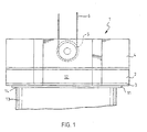
- Figure 1 is a side view illustrating a vacuum gripping apparatus of the invention and a paper roll;
- Figure 2 illustrates a suction plate of the vacuum gripping apparatus of the invention seen from below; and
- Figures 3 and 4 illustrate two matrices formed of rolls of different sizes, i.e. two ways of arranging rolls into a storage.
-
- A lower portion of a
vacuum gripping apparatus 1 shown in Figure 1 is provided with avacuum container 2 connected to a vacuum generator not shown here. Asuction plate 3 closes the underside of thevacuum container 2, a casing 4 being arranged above thevacuum container 2, the casing enclosing aggregates and devices, such as the vacuum generator, an emergency vacuum generator, batteries, electric switches, etc., associated with thevacuum gripping apparatus 1 and not described in detail in this context. In addition, inside the casing 4 there are pivoted guidingrolls 5 via which the vacuum gripping apparatus is liftably and lowerably suspended on ropes 6 of a lifting apparatus not described here in detail. - The underside of the
suction plate 3 is provided withseal rings 7 to 11 arranged one inside the other, theoutermost seal ring 11 following the form of theouter circumference 12 of thesuction plate 3, close to theouter circumference 12. Together with atop surface 14 of apaper roll 13 theseal rings 7 to 11form vacuum spaces 15 to 18 for lifting thepaper roll 13 by applying a vacuum generated into the spaces. - The
suction plate 3 is formed here as a substantially regular hexagon comprising comerportions 19 provided withbevels 20 to avoid sharp corners.Side edges 21 starting at the edges of thebevels 20 are inward concave, and to arrange the side edges with adjacentpaper roll stacks 22 and 23 (Figures 3 and 4), theside edges 21 are arranged concentric with the adjacentpaper roll stacks suction plate 3 is thereby provided with the greatest surface possible, maintaining at the same time the allowed distance between theside edges 21 and the covering surfaces of thepaper roll stacks - The
vacuum container 2 and the casing 4 can be made into any form, provided that their contours do not extend beyond theouter circumference 12 of thesuction plate 3 in lateral direction and that a vacuum can be provided into allvacuum spaces 15 to 18 when needed. In the example concerned the describedvacuum container 2 and casing 4 can be imagined to have a horizontal cross-section substantially of the same form as thesuction plate 3. - In Figures 3 and 4 the
vacuum gripping apparatus 1 is driven betweenpaper roll stacks vacuum gripping apparatus 1 being provided with thesuction plate 3 of the invention, the suction plate is able to lift rolls of considerably different sizes because, on one hand, it fits between paper roll stacks 22 of a smaller diameter and, on the other hand, it has sufficient suction power enabling rolls in paper roll stacks 23 of considerably larger diameter to be lifted. - The above description of the invention is only meant to illustrate the invention. A person skilled in the art may implement details of the invention in various alternative ways within the scope of the appended claims.
Claims (8)
- A vacuum gripping apparatus for moving roll-like loads (13), the loads being piled on top of each other and resting on their end faces and the vacuum gripping apparatus (1) comprising a suction plate (3) to be arranged against the end face of a load, characterized in that the outer circumference (12) of the suction plate (3) is provided with comer portions (19), the side edges (21) connecting the corners of the portions being curved inward, whereby the maximum lateral dimensions of the structure above the suction plate (3), are such as not to exceed the outer circumference (12) of the suction plate (3).
- A vacuum gripping apparatus according to claim 1, characterized in that the outer circumference (12) of the suction plate (3) is arranged in the form of a regular polygon.
- A vacuum gripping apparatus according to claim 2, characterized in that the outer circumference (12) of the suction plate (3) has six edges at equal distances.
- A vacuum gripping apparatus according to any one of claims 1 to 3, characterized in that the side edges (21) of the suction plate (3) are arched.
- A vacuum gripping apparatus according to any one of claims 1 to 4, characterized in that the corner portions (19) are beveled.
- A vacuum gripping apparatus according to any one of claims 1 to 5, characterized in that the outermost circumference of the vacuum gripping apparatus (1) comprises the outer circumference (12) of the suction plate (3).
- A vacuum gripping apparatus according to any one of claims 1. to 6, characterized in that the outer circumference (12) of the suction plate (3) forms the outermost circumference of the vacuum gripping apparatus (1).
- A vacuum gripping apparatus according to any one of claims 1 to 7, characterized in that the underside of the suction plate (3) is provided with a seal arrangement (7 to 11), the outermost seal (11) of which follows the contours of the outer circumference (12) of the suction plate (3).
Applications Claiming Priority (3)
| Application Number | Priority Date | Filing Date | Title |
|---|---|---|---|
| FI982299 | 1998-10-23 | ||
| FI982299A FI104552B (en) | 1998-10-23 | 1998-10-23 | Undertrycksgripare |
| PCT/FI1999/000882 WO2000024665A1 (en) | 1998-10-23 | 1999-10-22 | Vacuum gripping apparatus |
Publications (2)
| Publication Number | Publication Date |
|---|---|
| EP1056680A1 EP1056680A1 (en) | 2000-12-06 |
| EP1056680B1 true EP1056680B1 (en) | 2003-07-16 |
Family
ID=8552771
Family Applications (1)
| Application Number | Title | Priority Date | Filing Date |
|---|---|---|---|
| EP99954015A Expired - Lifetime EP1056680B1 (en) | 1998-10-23 | 1999-10-22 | Vacuum gripping apparatus |
Country Status (11)
| Country | Link |
|---|---|
| US (1) | US6375240B1 (en) |
| EP (1) | EP1056680B1 (en) |
| JP (1) | JP2002528360A (en) |
| AT (1) | ATE245121T1 (en) |
| CA (1) | CA2312388C (en) |
| DE (1) | DE69909595T2 (en) |
| DK (1) | DK1056680T3 (en) |
| ES (1) | ES2203200T3 (en) |
| FI (1) | FI104552B (en) |
| PT (1) | PT1056680E (en) |
| WO (1) | WO2000024665A1 (en) |
Families Citing this family (7)
| Publication number | Priority date | Publication date | Assignee | Title |
|---|---|---|---|---|
| US7520872B2 (en) * | 2002-09-13 | 2009-04-21 | Neogen Technologies, Inc. | Closed wound drainage system |
| US6979324B2 (en) * | 2002-09-13 | 2005-12-27 | Neogen Technologies, Inc. | Closed wound drainage system |
| DE102005009315A1 (en) * | 2005-02-18 | 2006-08-24 | Alfred Kärcher Gmbh & Co. Kg | fastening device |
| US8083712B2 (en) * | 2007-03-20 | 2011-12-27 | Neogen Technologies, Inc. | Flat-hose assembly for wound drainage system |
| ES2361726T3 (en) * | 2007-06-13 | 2011-06-21 | Frattini-Tech Ag | GRIP DEVICE AND HANDLING OF METAL CONTAINERS. |
| US9011393B2 (en) * | 2009-12-18 | 2015-04-21 | Kci Licensing, Inc. | Systems, methods, and devices for restoring lymphatic flow associated with a subcutaneous defect in a patients body |
| CN111847209A (en) * | 2020-07-15 | 2020-10-30 | 浙江农林大学暨阳学院 | Vacuum chuck device for digital manufacturing |
Family Cites Families (11)
| Publication number | Priority date | Publication date | Assignee | Title |
|---|---|---|---|---|
| US1505626A (en) * | 1922-11-14 | 1924-08-19 | Saint Gobain | Suction device for lifting and transporting articles having any kind of surface |
| US3376061A (en) * | 1966-02-03 | 1968-04-02 | Hyster Co | Suction load-handling apparatus |
| US3758144A (en) * | 1972-01-06 | 1973-09-11 | H Dalglish | Vacuum center lift |
| US3833251A (en) * | 1972-10-06 | 1974-09-03 | Aerovac Corp | Longitudinally stiffened flexible lifter for arcuate objects |
| US3926466A (en) | 1973-10-01 | 1975-12-16 | Ethyl Corp | Apparatus for handling rolls |
| DE8435161U1 (en) | 1984-11-30 | 1985-05-23 | Bartholomy & Co, 516O Düren | VACUUM LIFTER |
| US4925225A (en) * | 1989-06-19 | 1990-05-15 | Dost Incorporated | Vacuum lifting device for handling sheet material |
| DE9013528U1 (en) * | 1990-09-26 | 1991-04-11 | Bartholomy & Co, 516O Dueren, De | |
| DE9015109U1 (en) | 1990-11-02 | 1991-01-10 | Bartholomy & Co, 516O Dueren, De | |
| DE9101063U1 (en) | 1991-01-31 | 1991-04-18 | Rico-Maschinenbau Max Appel Kg, 7080 Aalen, De | |
| FI971382A (en) | 1997-04-03 | 1998-10-04 | Kci Kone Cranes Int Oy | Procedure for lifting load with a suppressor gripping tool |
-
1998
- 1998-10-23 FI FI982299A patent/FI104552B/en not_active IP Right Cessation
-
1999
- 1999-10-22 DK DK99954015T patent/DK1056680T3/en active
- 1999-10-22 EP EP99954015A patent/EP1056680B1/en not_active Expired - Lifetime
- 1999-10-22 DE DE69909595T patent/DE69909595T2/en not_active Expired - Lifetime
- 1999-10-22 AT AT99954015T patent/ATE245121T1/en active
- 1999-10-22 JP JP2000578241A patent/JP2002528360A/en active Pending
- 1999-10-22 WO PCT/FI1999/000882 patent/WO2000024665A1/en active IP Right Grant
- 1999-10-22 CA CA002312388A patent/CA2312388C/en not_active Expired - Fee Related
- 1999-10-22 PT PT99954015T patent/PT1056680E/en unknown
- 1999-10-22 ES ES99954015T patent/ES2203200T3/en not_active Expired - Lifetime
- 1999-10-22 US US09/582,331 patent/US6375240B1/en not_active Expired - Fee Related
Also Published As
| Publication number | Publication date |
|---|---|
| WO2000024665A1 (en) | 2000-05-04 |
| FI982299A0 (en) | 1998-10-23 |
| FI104552B (en) | 2000-02-29 |
| JP2002528360A (en) | 2002-09-03 |
| ATE245121T1 (en) | 2003-08-15 |
| PT1056680E (en) | 2003-11-28 |
| EP1056680A1 (en) | 2000-12-06 |
| US6375240B1 (en) | 2002-04-23 |
| DE69909595D1 (en) | 2003-08-21 |
| CA2312388A1 (en) | 2000-05-04 |
| CA2312388C (en) | 2009-12-29 |
| DK1056680T3 (en) | 2003-10-27 |
| DE69909595T2 (en) | 2004-05-27 |
| ES2203200T3 (en) | 2004-04-01 |
Similar Documents
| Publication | Publication Date | Title |
|---|---|---|
| EP1056680B1 (en) | Vacuum gripping apparatus | |
| GB2342946A (en) | Method and apparatus for the offshore installation of multi-ton packages such as deck packages and jackets | |
| ATE420998T1 (en) | METHOD AND APPARATUS FOR INSTALLING PREFABRICATED DECK CONSTRUCTIONS ON OFFSHORE LIFTING FOUNDATIONS | |
| CA2217548A1 (en) | Counterweight handling system for ring-supported cranes | |
| CA2265684A1 (en) | A can with a cover provided with a pull ring | |
| CN204597312U (en) | Box-type substation | |
| CN215666631U (en) | Lifting device for hub of wind generating set | |
| US5600686A (en) | Method for replacing a component located in the interior of a containment of a nuclear reactor | |
| FI94615C (en) | A vacuum lifter | |
| IT1262591B (en) | SYSTEM FOR SORTING, FORMING AND REMOVAL OF PILE, MULTI-SIZE CERAMIC TILES. | |
| CN216836730U (en) | Bolt type lower hanging beam for hoisting laminated slab | |
| KR102023707B1 (en) | Crane | |
| CN214827386U (en) | Adjustable environment-friendly warehouse-out loss reduction device with convenient disassembly for squat silo | |
| CN215622100U (en) | Material conveyer for building engineering | |
| CN217417891U (en) | Be applicable to shaft maintenance and construction and use hoist and mount instrument | |
| CN212893544U (en) | Transportation hoisting device for installation of storage tank in limited space | |
| CN214298955U (en) | Precast beam slab acute angle protection device | |
| CN211895162U (en) | Building cement building block handling device | |
| CN219009269U (en) | Electric core stacking device | |
| CN114583633B (en) | Construction method of movable lever type cable shaft bracket | |
| CN211594741U (en) | Driving lifting device for steel coil processing production line | |
| CN207234217U (en) | A kind of solar energy substation | |
| CN115288202A (en) | Reinforced cement cover plate convenient to replace | |
| JPH074058A (en) | Method and equipment for lifting pc wall slab of multistoried building | |
| JP2596283B2 (en) | Omnidirectional solid gantry |
Legal Events
| Date | Code | Title | Description |
|---|---|---|---|
| PUAI | Public reference made under article 153(3) epc to a published international application that has entered the european phase |
Free format text: ORIGINAL CODE: 0009012 |
|
| 17P | Request for examination filed |
Effective date: 20000616 |
|
| AK | Designated contracting states |
Kind code of ref document: A1 Designated state(s): AT BE CH CY DE DK ES FI FR GB GR IE IT LI LU MC NL PT SE |
|
| 17Q | First examination report despatched |
Effective date: 20020402 |
|
| GRAH | Despatch of communication of intention to grant a patent |
Free format text: ORIGINAL CODE: EPIDOS IGRA |
|
| GRAH | Despatch of communication of intention to grant a patent |
Free format text: ORIGINAL CODE: EPIDOS IGRA |
|
| GRAA | (expected) grant |
Free format text: ORIGINAL CODE: 0009210 |
|
| RAP1 | Party data changed (applicant data changed or rights of an application transferred) |
Owner name: KCI KONECRANES PLC |
|
| AK | Designated contracting states |
Designated state(s): AT BE CH CY DE DK ES FI FR GB GR IE IT LI LU MC NL PT SE |
|
| PG25 | Lapsed in a contracting state [announced via postgrant information from national office to epo] |
Ref country code: FI Free format text: LAPSE BECAUSE OF FAILURE TO SUBMIT A TRANSLATION OF THE DESCRIPTION OR TO PAY THE FEE WITHIN THE PRESCRIBED TIME-LIMIT Effective date: 20030716 |
|
| REG | Reference to a national code |
Ref country code: GB Ref legal event code: FG4D |
|
| REG | Reference to a national code |
Ref country code: CH Ref legal event code: EP |
|
| REG | Reference to a national code |
Ref country code: IE Ref legal event code: FG4D |
|
| REF | Corresponds to: |
Ref document number: 69909595 Country of ref document: DE Date of ref document: 20030821 Kind code of ref document: P |
|
| REG | Reference to a national code |
Ref country code: CH Ref legal event code: NV Representative=s name: WERNER BRUDERER PATENTANWALT |
|
| PG25 | Lapsed in a contracting state [announced via postgrant information from national office to epo] |
Ref country code: LU Free format text: LAPSE BECAUSE OF NON-PAYMENT OF DUE FEES Effective date: 20031022 Ref country code: CY Free format text: LAPSE BECAUSE OF FAILURE TO SUBMIT A TRANSLATION OF THE DESCRIPTION OR TO PAY THE FEE WITHIN THE PRESCRIBED TIME-LIMIT Effective date: 20031022 |
|
| PG25 | Lapsed in a contracting state [announced via postgrant information from national office to epo] |
Ref country code: MC Free format text: LAPSE BECAUSE OF NON-PAYMENT OF DUE FEES Effective date: 20031031 |
|
| REG | Reference to a national code |
Ref country code: SE Ref legal event code: TRGR |
|
| REG | Reference to a national code |
Ref country code: GR Ref legal event code: EP Ref document number: 20030403989 Country of ref document: GR |
|
| REG | Reference to a national code |
Ref country code: ES Ref legal event code: FG2A Ref document number: 2203200 Country of ref document: ES Kind code of ref document: T3 |
|
| ET | Fr: translation filed | ||
| PLBE | No opposition filed within time limit |
Free format text: ORIGINAL CODE: 0009261 |
|
| STAA | Information on the status of an ep patent application or granted ep patent |
Free format text: STATUS: NO OPPOSITION FILED WITHIN TIME LIMIT |
|
| 26N | No opposition filed |
Effective date: 20040419 |
|
| REG | Reference to a national code |
Ref country code: CH Ref legal event code: NV Representative=s name: FREI PATENTANWALTSBUERO AG |
|
| PGFP | Annual fee paid to national office [announced via postgrant information from national office to epo] |
Ref country code: DK Payment date: 20121025 Year of fee payment: 14 |
|
| PGFP | Annual fee paid to national office [announced via postgrant information from national office to epo] |
Ref country code: FR Payment date: 20121205 Year of fee payment: 14 Ref country code: BE Payment date: 20121029 Year of fee payment: 14 Ref country code: CH Payment date: 20121017 Year of fee payment: 14 Ref country code: IE Payment date: 20121017 Year of fee payment: 14 |
|
| PGFP | Annual fee paid to national office [announced via postgrant information from national office to epo] |
Ref country code: GB Payment date: 20121024 Year of fee payment: 14 Ref country code: PT Payment date: 20120423 Year of fee payment: 14 Ref country code: IT Payment date: 20121025 Year of fee payment: 14 Ref country code: ES Payment date: 20121018 Year of fee payment: 14 Ref country code: GR Payment date: 20121029 Year of fee payment: 14 Ref country code: SE Payment date: 20121024 Year of fee payment: 14 |
|
| PGFP | Annual fee paid to national office [announced via postgrant information from national office to epo] |
Ref country code: NL Payment date: 20121024 Year of fee payment: 14 Ref country code: AT Payment date: 20121030 Year of fee payment: 14 |
|
| BERE | Be: lapsed |
Owner name: *KCI KONECRANES P.L.C. Effective date: 20131031 |
|
| REG | Reference to a national code |
Ref country code: PT Ref legal event code: MM4A Free format text: LAPSE DUE TO NON-PAYMENT OF FEES Effective date: 20140422 |
|
| REG | Reference to a national code |
Ref country code: NL Ref legal event code: V1 Effective date: 20140501 |
|
| REG | Reference to a national code |
Ref country code: DK Ref legal event code: EBP Effective date: 20131031 |
|
| REG | Reference to a national code |
Ref country code: CH Ref legal event code: PL |
|
| REG | Reference to a national code |
Ref country code: SE Ref legal event code: EUG |
|
| REG | Reference to a national code |
Ref country code: AT Ref legal event code: MM01 Ref document number: 245121 Country of ref document: AT Kind code of ref document: T Effective date: 20131022 |
|
| GBPC | Gb: european patent ceased through non-payment of renewal fee |
Effective date: 20131022 |
|
| REG | Reference to a national code |
Ref country code: GR Ref legal event code: ML Ref document number: 20030403989 Country of ref document: GR Effective date: 20140505 |
|
| REG | Reference to a national code |
Ref country code: IE Ref legal event code: MM4A |
|
| PG25 | Lapsed in a contracting state [announced via postgrant information from national office to epo] |
Ref country code: GB Free format text: LAPSE BECAUSE OF NON-PAYMENT OF DUE FEES Effective date: 20131022 Ref country code: LI Free format text: LAPSE BECAUSE OF NON-PAYMENT OF DUE FEES Effective date: 20131031 Ref country code: CH Free format text: LAPSE BECAUSE OF NON-PAYMENT OF DUE FEES Effective date: 20131031 |
|
| REG | Reference to a national code |
Ref country code: FR Ref legal event code: ST Effective date: 20140630 |
|
| PG25 | Lapsed in a contracting state [announced via postgrant information from national office to epo] |
Ref country code: FR Free format text: LAPSE BECAUSE OF NON-PAYMENT OF DUE FEES Effective date: 20131031 Ref country code: GR Free format text: LAPSE BECAUSE OF NON-PAYMENT OF DUE FEES Effective date: 20140505 Ref country code: AT Free format text: LAPSE BECAUSE OF NON-PAYMENT OF DUE FEES Effective date: 20131022 Ref country code: NL Free format text: LAPSE BECAUSE OF NON-PAYMENT OF DUE FEES Effective date: 20140501 Ref country code: SE Free format text: LAPSE BECAUSE OF NON-PAYMENT OF DUE FEES Effective date: 20131023 Ref country code: IT Free format text: LAPSE BECAUSE OF NON-PAYMENT OF DUE FEES Effective date: 20131022 Ref country code: PT Free format text: LAPSE BECAUSE OF NON-PAYMENT OF DUE FEES Effective date: 20140422 |
|
| PG25 | Lapsed in a contracting state [announced via postgrant information from national office to epo] |
Ref country code: BE Free format text: LAPSE BECAUSE OF NON-PAYMENT OF DUE FEES Effective date: 20131031 |
|
| PG25 | Lapsed in a contracting state [announced via postgrant information from national office to epo] |
Ref country code: IE Free format text: LAPSE BECAUSE OF NON-PAYMENT OF DUE FEES Effective date: 20131022 Ref country code: DK Free format text: LAPSE BECAUSE OF NON-PAYMENT OF DUE FEES Effective date: 20131031 |
|
| REG | Reference to a national code |
Ref country code: ES Ref legal event code: FD2A Effective date: 20150504 |
|
| PG25 | Lapsed in a contracting state [announced via postgrant information from national office to epo] |
Ref country code: ES Free format text: LAPSE BECAUSE OF NON-PAYMENT OF DUE FEES Effective date: 20131023 |
|
| PGFP | Annual fee paid to national office [announced via postgrant information from national office to epo] |
Ref country code: DE Payment date: 20151026 Year of fee payment: 17 |
|
| REG | Reference to a national code |
Ref country code: DE Ref legal event code: R082 Ref document number: 69909595 Country of ref document: DE Representative=s name: RUEGER ABEL PATENT- UND RECHTSANWAELTE, DE Ref country code: DE Ref legal event code: R082 Ref document number: 69909595 Country of ref document: DE Representative=s name: RUEGER, BARTHELT & ABEL, DE Ref country code: DE Ref legal event code: R081 Ref document number: 69909595 Country of ref document: DE Owner name: KONECRANES GLOBAL CORPORATION, FI Free format text: FORMER OWNER: KCI KONECRANES PLC, HYVINKAEAE, FI |
|
| REG | Reference to a national code |
Ref country code: DE Ref legal event code: R119 Ref document number: 69909595 Country of ref document: DE |
|
| PG25 | Lapsed in a contracting state [announced via postgrant information from national office to epo] |
Ref country code: DE Free format text: LAPSE BECAUSE OF NON-PAYMENT OF DUE FEES Effective date: 20170503 |