EP1055947A1 - Wechselsystem für optische Komponenten - Google Patents
Wechselsystem für optische Komponenten Download PDFInfo
- Publication number
- EP1055947A1 EP1055947A1 EP00107639A EP00107639A EP1055947A1 EP 1055947 A1 EP1055947 A1 EP 1055947A1 EP 00107639 A EP00107639 A EP 00107639A EP 00107639 A EP00107639 A EP 00107639A EP 1055947 A1 EP1055947 A1 EP 1055947A1
- Authority
- EP
- European Patent Office
- Prior art keywords
- exchange system
- components
- columns
- flanges
- turret
- Prior art date
- Legal status (The legal status is an assumption and is not a legal conclusion. Google has not performed a legal analysis and makes no representation as to the accuracy of the status listed.)
- Granted
Links
- 230000003287 optical effect Effects 0.000 title claims description 17
- 238000000034 method Methods 0.000 description 2
- 230000002093 peripheral effect Effects 0.000 description 2
- 230000015572 biosynthetic process Effects 0.000 description 1
- 230000001419 dependent effect Effects 0.000 description 1
- 238000004512 die casting Methods 0.000 description 1
- 239000011521 glass Substances 0.000 description 1
- 238000003780 insertion Methods 0.000 description 1
- 230000037431 insertion Effects 0.000 description 1
- 230000013011 mating Effects 0.000 description 1
- 238000000386 microscopy Methods 0.000 description 1
Images

Classifications
-
- G—PHYSICS
- G02—OPTICS
- G02B—OPTICAL ELEMENTS, SYSTEMS OR APPARATUS
- G02B7/00—Mountings, adjusting means, or light-tight connections, for optical elements
- G02B7/02—Mountings, adjusting means, or light-tight connections, for optical elements for lenses
- G02B7/14—Mountings, adjusting means, or light-tight connections, for optical elements for lenses adapted to interchange lenses
- G02B7/16—Rotatable turrets
Definitions
- the invention relates to a changing system for optical components such as filters, reflectors, Polarizers or lens systems in optical devices, especially microscopes.
- optical components such as filters, reflectors, Polarizers or lens systems in optical devices, especially microscopes.
- Such changing systems are used to different lighting and / or Contrast method or different re-enlargements, for example in the To enable microscopy.
- Such change systems usually have either one Slider slidable perpendicular to the beam paths of the optical device or a revolver on the microscope stand, on which the different optical components bearing components are interchangeably included.
- By Switching the slide or the turret can then optionally use different modules, which are equipped with different lens combinations, reflectors or filters, in be brought to the beam path.
- the aim of the present invention is an exchange system for optical components optical devices, in which the assembly with or the replacement of components with the optical components are equipped, is simplified.
- the invention is intended in particular can be used as a reflector and / or filter changer.
- those with various optical components components such as reflectors, filters, polarizers or magnification systems Spring force held against precise stops of the changing system. It has been more surprising Way out that a relatively easy springing of the components Sufficient reproducibility can be achieved with high-performance microscopes and this reproducibility also with the mechanical movement of the changing system is maintained.
- Simple leaf springs can be provided for generating the spring force.
- the components equipped with the optical components preferably have two each Flanges that are pressed by the springs against two parallel angles on the change system become.
- the angles on the change system can be perpendicular to each other standing areas are formed.
- Each flange is preferably two leaf springs assigned, whose directions of force are at an angle not equal to 90 ° to each other.
- the Force direction of the stronger spring should be in the direction of the diagonal of the assigned Flange act, so that by this stronger spring of the flange in the angle of Change system is pressed.
- the weaker spring then presses the flange against one of the two surfaces of the changing system assigned to the flange.
- the change system according to the invention can in particular be designed as a rotatable turret his.
- the stops of the changing system are then preferably provided on columns that extend parallel to the direction of rotation of the revolver.
- the columns can each between the light passage openings of adjacent switch positions of the revolver be provided so that each pillar stops for two adjacent receiving positions for reflector trestles.
- the columns are preferably in the peripheral area of the Revolvers provided, i.e. is the distance of the columns from the axis of rotation of the turret greater than the distance between the centers of the light passage openings of the changing system from the axis of rotation of the revolver. This allows an optimally dense arrangement of the Reach positions for the reflector trestles on the revolver, causing again an optimum of switching positions of the revolver for a given one Revolver diameter and specified space requirement for each reflector block results.
- the changing system (1) in Figure 1 has a turret (4) around her Center axis (2) is rotatable.
- the revolver disc (4) has one on its peripheral edge Teeth (14) into which the teeth of a toothed belt driven by a motor (12) (13) intervene.
- the changing system has a detent (15) through which it is ensured that after each rotation of the turret disc (4) the rotary movement in a defined switching position is stopped.
- the turret disk (4) has a total of 8 with its center points on a circle light passage openings (3a -) arranged around the axis of rotation (2) of the turret disk (4) 3h), which each define a switching position of the revolver. 1
- the situation shown here is the recording positions for five reflector trestles Switch positions (3a, 3b, 3e, 3f and 3g) empty, while the recording positions for Reflector blocks for three switch positions (3c, 3d and 3h) equipped with reflector blocks (9) are.
- the reflector blocks are essentially cube-shaped and have three light passage openings, two of which are coaxial to one another and one is perpendicular to the other two.
- Each of the columns (5) has two radially outwards and thus parallel to the axis of rotation (2) of the Revolver-oriented surfaces (6a, 6b).
- the angle between these two surfaces (6a, 6b) corresponds to the angle of rotation of the turret disk (4) between two Switch positions.
- the one light passage opening (3a) of the turret disk (4) Adjacent surface (6a) of the column (5) serves as a contact surface for one in the this light passage opening (3a) defined recording position to be recorded Reflector frame.
- the area (6b) adjacent to the adjacent light passage opening (3b) the column (5) serves accordingly as a contact surface for one in the by the neighboring Light passage opening (3b) defined recording position to be taken reflector block.
- the distances of the radially outward contact surfaces (6a, 6b) from the axis of rotation (2) of the revolver are larger than the distance between the centers of the Light passage openings (3a - 3h) from the axis of rotation of the revolver.
- Each of the columns (5) has two further contact surfaces (6c), which are perpendicular to the two stand radially outward contact surfaces (6a, 6b) of the column (5).
- One each Form receiving position for contact surfaces (6a, 6c) assigned to reflector blocks accordingly an inside angle of 90 °.
- Leaf springs may be provided, each of which is designed as each of the two legs of the Double leaf spring.
- the use of two individual leaf springs is particularly evident in Revolvers with a smaller number of switching positions and with sliders than Exchange system as advantageous.
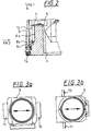
- the reflector trestles to be accommodated on the changing system are shown in FIGS. 3a and 3b shown. They essentially consist of two housing halves, which together form one cube-shaped hollow body (9) with three circular openings for the passage of light form. Each of the two housing halves corresponds to half along one Area diagonal cut cubes. Inside the hollow body are the optical ones Components arranged for use as a reflector, for example, parallel to one another Bisecting mirror or, in the case of a filter, parallel to the Filter glasses extending cube surfaces. For use as magnification changers Lens groups, which together form a telescope, parallel to the light passage openings intended.
- the second half of the case is a Plastic part that has a relatively low precision and only for holding Filter or to press reflectors against contact surfaces of the other housing part serves.
- the flanges (10, 11) are symmetrical to the centers of the light passage openings formed and arranged accordingly symmetrically on the housing part in question, so that the reflector trestles in two positions rotated by 180 ° depending on the application same precision can be recorded in the turret.
- the reflector bracket (9) to be picked up is first with one Edge of each of the two flanges (10, 11) behind that adjacent to the turret disk (4) Leaf springs (8a) inserted into the two columns assigned to the receiving position.
- the The reflector bracket (9) becomes perpendicular by about 10 ° to the plane of the drawing in FIG. 2 standing axis rotated relative to the final recording position.
- the free end of the leaf springs is to facilitate insertion of the edges of the flanges (10, 11) (8a) bent away from the contact surface (6a) of the columns (5).
- Inserting the flanges (10, 11) therefore takes place against the spring force of the leaf springs (8a).
- the leaf springs (8a) press in the direction of arrow PK 2 against the flanges (10, 11) and press them against the outward contact surfaces (6a) of the columns (5) on opposite sides the light passage opening.
- the reflector bracket is rotated about a perpendicular to the plane of the drawing axis in FIG. 2.
- the V-shaped ends are free trained second leaf springs (7) of two columns (5) deflected against their spring force.
- the reflector bracket (9) slide over the tips of the V of the leaf springs (7) the edges of the flanges (10, 11) and press the flanges (10, 11) against the short, Contact surfaces (6c) of both columns standing perpendicular to the axis of rotation of the turret.
- the contact surfaces of the flanges (10, 11) on the Contact surfaces (6a, 6c) of the columns (5) are the contact surfaces of the flanges (10, 11) on the Contact surfaces (6a, 6c) of the columns (5).
- the shape and length of the leaf springs (7) is in Depending on the dimensions of the flanges (10, 11) chosen so that in the end position the flanges (10, 11) the forces exerted by the leaf springs (7) on the flanges in the direction of the contact surfaces (6a, 6c) perpendicular to each other formed inner edges act. This direction of force is shown in FIG. 2 by the arrow PK1 indicated.
- the contact surfaces (6a, 6c) and the corresponding Mating surfaces of the flanges (10, 11) of the reflector blocks are when changing or inserting and Removing the reflector brackets achieves a reproducible accuracy of ⁇ 0.01mm.
- the Angular accuracy of the recording is within one minute of arc.
- the spring clamping according to the invention of the reflector blocks on the changing system enables a quick and easy assembly of the changing system with reflector trestles or a replace the reflector trestles. Tools are not required.
Landscapes
- Physics & Mathematics (AREA)
- General Physics & Mathematics (AREA)
- Optics & Photonics (AREA)
- Microscoopes, Condenser (AREA)
- Lens Barrels (AREA)
- Laser Surgery Devices (AREA)
- Glass Compositions (AREA)
- Mounting And Adjusting Of Optical Elements (AREA)
- Mechanical Light Control Or Optical Switches (AREA)
Abstract
Description
- Figur 1:
- Eine perspektivische Ansicht eines Wechselsystems nach der Erfindung.
- Figur 2:
- Einen Teil des Wechselsystems in Figur 1 im Schnitt.
- Figuren 3a und 3b:
- Die Ansicht eines Ausführungsbeispiels für einen Reflektorbock aus zwei zueinander senkrechten Richtungen.
Claims (15)
- Wechselsystem für optische Komponenten bei optischen Geräten, insbesondere Mikroskopen, mit mehreren jeweils verschiedene optische Komponenten tragenden Bauteilen (9), wobei die Bauteile (9) durch Federkraft gegen Anschläge (6a, 6c) des Wechselsystems (1) gehalten sind.
- Wechselsystem nach Anspruch 1, wobei für die Erzeugung der Federkraft Blattfedern (7, 8a, 8b) vorgesehen sind.
- Wechselsystem nach Anspruch 1 oder 2, wobei die Bauteile (9) Flansche (10, 11) aufweisen, die gegen von jeweils zwei zueinander senkrecht stehenden Flächen (6a, 6c) gebildete Winkel am Wechselsystem gedrückt werden.
- Wechselsystem nach Anspruch 3, wobei jedem Flansch (10, 11) zwei Blattfedern (7, 8a) zugeordnet sind, deren Kraftrichtungen ungleich 90° geneigt zueinander stehen.
- Wechselsystem nach Anspruch 3 oder 4, wobei die Flansche (10, 11) seitlich der Bauteile (9) angeordnet sind und die Abmessungen der Bauteile (9) seitlich überragen.
- Wechselsystem nach einem der Ansprüche 1 - 5, wobei das Wechselsystem als drehbarer Revolver ausgebildet ist.
- Wechselsystem nach Anspruch 6, wobei die Anschläge an sich parallel zur Drehachse (2) des Revolvers erstreckenden Säulen (5) ausgebildet sind.
- Wechselsystem nach Anspruch 7, wobei die Säulen (5) zwischen den Lichtdurchtrittsöffnungen (3a - 3h) jeweils benachbarter Schaltstellungen des Revolvers angeordnet sind.
- Wechselsystem nach Anspruch 8, wobei jeweils zwei benachbarte Säulen (5) parallele Anschläge aufweisen.
- Wechselsystem nach Anspruch 8 oder 9, wobei der Abstand der Säulen (5) von der Drehachse (2) des Revolvers größer als der Abstand der Mittelpunkte der Lichtdurchtrittsöffnungen (3a - 3h) von der Drehachse (2) des Revolvers ist.
- Wechselsystem nach einem der Ansprüche 1 - 10, wobei ein motorischer Antrieb (12, 13, 14) für die Schaltung des Wechselsystems vorgesehen ist.
- Wechselsystem nach einem der Ansprüche 1 - 11, wobei die optischen Komponenten Reflektoren, Filter, Polarisatoren oder teleskopische Linsensysteme sind.
- Wechselsystem nach einem der Ansprüche 3 - 12, wobei die Flansche (10, 11) symmetrisch zu Lichtdurchtrittsöffnungen angeordnet sind, so daß die Bauteile in zwei um 180° verdrehten Stellungen am Wechselsystem (1) aufnehmbar sind.
- Wechselsystem nach einem der Ansprüche 3 - 13, wobei die Bauteile (9) aus zwei Gehäusehälften bestehen und die Flansche (10, 11) an einer Gehäusehälfte angeordnet sind.
- Wechselsystem nach einem der Ansprüche 4 - 14, wobei eine der Blattfedern (7) V-förmig ausgebildet ist und so bemessen ist, daß bei aufgenommenen Bauteil (9) eine Kante des Flansches (10, 11) an der dem freien Ende der Blattfeder abgewandte Flanke des V anliegt.
Applications Claiming Priority (2)
| Application Number | Priority Date | Filing Date | Title |
|---|---|---|---|
| DE19924686A DE19924686A1 (de) | 1999-05-28 | 1999-05-28 | Wechselsystem für optische Komponenten |
| DE19924686 | 1999-05-28 |
Publications (2)
| Publication Number | Publication Date |
|---|---|
| EP1055947A1 true EP1055947A1 (de) | 2000-11-29 |
| EP1055947B1 EP1055947B1 (de) | 2010-12-22 |
Family
ID=7909613
Family Applications (1)
| Application Number | Title | Priority Date | Filing Date |
|---|---|---|---|
| EP00107639A Expired - Lifetime EP1055947B1 (de) | 1999-05-28 | 2000-04-08 | Wechselsystem für optische Komponenten |
Country Status (5)
| Country | Link |
|---|---|
| US (1) | US6392796B1 (de) |
| EP (1) | EP1055947B1 (de) |
| JP (1) | JP4843775B2 (de) |
| AT (1) | ATE492830T1 (de) |
| DE (2) | DE19924686A1 (de) |
Families Citing this family (11)
| Publication number | Priority date | Publication date | Assignee | Title |
|---|---|---|---|---|
| DE10112706B4 (de) * | 2001-03-16 | 2004-01-29 | Leica Microsystems Wetzlar Gmbh | Verstelleinheit |
| DE10309138A1 (de) | 2003-02-28 | 2004-09-16 | Till I.D. Gmbh | Mikroskopvorrichtung |
| DE102004016433A1 (de) * | 2004-03-31 | 2005-10-20 | Zeiss Carl Jena Gmbh | Anordnung zur Veränderung der Auskopplung des Objektlichtes und/oder der Einkopplung von Licht für ein Laser-Scanning-Mikroskop |
| DE102004034845B4 (de) * | 2004-07-19 | 2006-05-18 | Leica Microsystems Cms Gmbh | Umschaltbares Mikroskop |
| DE102006024109A1 (de) * | 2006-05-19 | 2007-11-22 | Carl Zeiss Microimaging Gmbh | Mikroskop mit Wechseleinrichtung für optische Elemente |
| DE102009035365B3 (de) * | 2009-07-30 | 2011-03-17 | Leica Microsystems Cms Gmbh | Einrichtung zum Positionieren von optischen Komponenten in einem optischen Gerät |
| DE102011051949B4 (de) | 2011-07-19 | 2017-05-18 | Leica Microsystems Cms Gmbh | Wechselvorrichtung für ein Mikroskop |
| DE102011108132B4 (de) * | 2011-07-20 | 2021-07-29 | Carl Zeiss Microscopy Gmbh | Revolver für optische Elemente eines Mikroskops und Mikroskop/Mikroskopmodul mit einem solchen Revolver |
| DE102012003984A1 (de) | 2012-02-28 | 2013-08-29 | Carl Zeiss Microscopy Gmbh | Wechseleinrichtung für optische Komponenten an einem Mikroskop |
| CN105258686B (zh) * | 2015-10-22 | 2019-02-01 | 青岛镭创光电技术有限公司 | 激光投线仪 |
| DE102020207026A1 (de) | 2020-06-04 | 2021-12-09 | Carl Zeiss Microscopy Gmbh | Wechseleinrichtung für optische Komponenten in einem Mikroskop |
Citations (4)
| Publication number | Priority date | Publication date | Assignee | Title |
|---|---|---|---|---|
| DE2316386A1 (de) * | 1973-04-02 | 1974-10-10 | Leitz Ernst Gmbh | Fluoreszenzauflichtilluminator |
| DE3627182A1 (de) * | 1985-11-01 | 1987-05-07 | Jenoptik Jena Gmbh | Elektromechanisch bewegte wechseleinrichtung fuer optisch wirksame elemente |
| US5128808A (en) * | 1989-11-15 | 1992-07-07 | Olympus Optical Co., Ltd. | Turret condenser for microscopes |
| WO1994007173A1 (de) * | 1992-09-19 | 1994-03-31 | Leica Mikroskopie Und Systeme Gmbh | Wechselvorrichtung mit zentrierbaren aufnahmeringen |
Family Cites Families (16)
| Publication number | Priority date | Publication date | Assignee | Title |
|---|---|---|---|---|
| US2720138A (en) * | 1950-04-15 | 1955-10-11 | Zeiss Carl | Supplementary apparatus for microscopes |
| US3488109A (en) * | 1967-04-17 | 1970-01-06 | Zeiss Jena Veb Carl | Objective changing devices |
| CH567733A5 (de) * | 1973-04-02 | 1975-10-15 | Leitz Ernst Gmbh | |
| US4544236A (en) * | 1981-11-02 | 1985-10-01 | Olympus Optical Co., Ltd. | Turret |
| JPS58157304U (ja) * | 1982-04-16 | 1983-10-20 | 株式会社ニコン | 対物レボルバ−の電動回転装置 |
| JPS62175933A (ja) * | 1986-01-29 | 1987-08-01 | Olympus Optical Co Ltd | アクチユエ−タの傾き調整装置 |
| SU1472860A1 (ru) * | 1987-08-10 | 1989-04-15 | Предприятие П/Я Р-6947 | Поворотна турель дл смены оптических элементов |
| JPH0641209Y2 (ja) * | 1988-01-26 | 1994-10-26 | 富士ゼロックス株式会社 | 反射ミラーの支持構造 |
| JPH0436713A (ja) * | 1990-06-01 | 1992-02-06 | Fuji Photo Film Co Ltd | ミラー固定装置 |
| JPH0735981A (ja) * | 1993-07-22 | 1995-02-07 | Olympus Optical Co Ltd | 光学素子交換装置 |
| JP3425810B2 (ja) * | 1994-07-27 | 2003-07-14 | オリンパス光学工業株式会社 | 光学系切換装置 |
| US5617260A (en) * | 1995-04-03 | 1997-04-01 | Wescam Inc. | Optical instrument with rotatable lens turret |
| JP3861363B2 (ja) * | 1996-11-12 | 2006-12-20 | 株式会社ニコン | 光学素子切換機構 |
| JPH10221581A (ja) * | 1997-02-12 | 1998-08-21 | Fuji Xerox Co Ltd | 光学部品取付構造 |
| JPH1130753A (ja) * | 1997-07-10 | 1999-02-02 | Olympus Optical Co Ltd | 光学顕微鏡 |
| JP3694154B2 (ja) * | 1997-09-30 | 2005-09-14 | ペンタックス株式会社 | レンズ位置調整固定装置及びレンズ位置調整固定方法 |
-
1999
- 1999-05-28 DE DE19924686A patent/DE19924686A1/de not_active Withdrawn
-
2000
- 2000-04-08 EP EP00107639A patent/EP1055947B1/de not_active Expired - Lifetime
- 2000-04-08 AT AT00107639T patent/ATE492830T1/de active
- 2000-04-08 DE DE50016047T patent/DE50016047D1/de not_active Expired - Lifetime
- 2000-05-26 JP JP2000156074A patent/JP4843775B2/ja not_active Expired - Lifetime
- 2000-05-30 US US09/584,014 patent/US6392796B1/en not_active Expired - Lifetime
Patent Citations (4)
| Publication number | Priority date | Publication date | Assignee | Title |
|---|---|---|---|---|
| DE2316386A1 (de) * | 1973-04-02 | 1974-10-10 | Leitz Ernst Gmbh | Fluoreszenzauflichtilluminator |
| DE3627182A1 (de) * | 1985-11-01 | 1987-05-07 | Jenoptik Jena Gmbh | Elektromechanisch bewegte wechseleinrichtung fuer optisch wirksame elemente |
| US5128808A (en) * | 1989-11-15 | 1992-07-07 | Olympus Optical Co., Ltd. | Turret condenser for microscopes |
| WO1994007173A1 (de) * | 1992-09-19 | 1994-03-31 | Leica Mikroskopie Und Systeme Gmbh | Wechselvorrichtung mit zentrierbaren aufnahmeringen |
Also Published As
| Publication number | Publication date |
|---|---|
| US6392796B1 (en) | 2002-05-21 |
| DE19924686A1 (de) | 2000-11-30 |
| JP4843775B2 (ja) | 2011-12-21 |
| DE50016047D1 (de) | 2011-02-03 |
| EP1055947B1 (de) | 2010-12-22 |
| JP2001004922A (ja) | 2001-01-12 |
| ATE492830T1 (de) | 2011-01-15 |
Similar Documents
| Publication | Publication Date | Title |
|---|---|---|
| EP1160609B1 (de) | Vorrichtung zur präzisen Positionierung eines Bauteiles, insbesondere eines optischen Bauteiles | |
| EP0267352B1 (de) | Vorrichtung zur wiederholbaren, hochgenauen Festlegung der relativen räumlichen Lage eines ersten Gegenstandes in Bezug auf zweite Gegenstände | |
| EP1055947B1 (de) | Wechselsystem für optische Komponenten | |
| DE69119483T2 (de) | Elektrooptische Abtasteinrichtung sowie mit der Abtasteinrichtung versehener optischer Spieler | |
| DE202009012924U1 (de) | Einschub zur Halterung einer Optik in einem Laserbearbeitungskopf sowie ein Laserbearbeitungskopf | |
| EP2549320A1 (de) | Wechselvorrichtung für ein Mikroskop | |
| DE3219399C2 (de) | Bausatz zum Aufbau einer mikrooptischen Bank | |
| DE4041873A1 (de) | Fuehrungseinrichtung mit einem kurvenring | |
| DE3610692C2 (de) | ||
| EP2018585B1 (de) | Mikroskop mit wechseleinrichtung für optische elemente | |
| DE102004061901B4 (de) | Einrichtung zur Halterung von optischen Komponenten | |
| EP2163345A1 (de) | Spannsystem und Spanneinrichtung mit einer zentralen Aufnahme für ein zu spannendes Werkstück | |
| EP3563953A1 (de) | Ausrichtvorrichtung, ausrichtelement für eine solche ausrichtvorrichtung und ausrichtverfahren | |
| DE20118456U1 (de) | Werkzeugmaschine | |
| DE10339255A1 (de) | Führungssystem für optische Systeme, insbesondere Zoom-Systeme | |
| DE10251379A1 (de) | Magnetisch positionierte Präzisionshalterung für Optikbauteile | |
| DE2351455C2 (de) | Unter dem Objekttisch eines Mikroskops anbringbare Revolveranordnung | |
| DE19936497C2 (de) | Halterung zur Befestigung einer Komponente mit einem aussenseitig angeordneten, symmetrischen Schwalbenschwanzschlitten | |
| DE69219005T2 (de) | Optischer Kopfantrieb | |
| DE10015186B4 (de) | Objektivfassung | |
| DE4231440A1 (de) | Universal-Klappkondensor für Mikroskope | |
| EP1122575B1 (de) | Vorrichtung zum Positionieren eines optischen Bauteils in einem Strahlengang | |
| DE102020103634B4 (de) | Werkstückspannvorrichtung mit einer Justageeinrichtung für eine Lagereinheit | |
| DE102008007772A1 (de) | Universalmodulatorscheibe für Kondensoranordnungen | |
| EP0657758A1 (de) | Kondensor und damit ausgerüstetes Mikroskop |
Legal Events
| Date | Code | Title | Description |
|---|---|---|---|
| PUAI | Public reference made under article 153(3) epc to a published international application that has entered the european phase |
Free format text: ORIGINAL CODE: 0009012 |
|
| AK | Designated contracting states |
Kind code of ref document: A1 Designated state(s): AT CH DE FR GB LI NL |
|
| AX | Request for extension of the european patent |
Free format text: AL;LT;LV;MK;RO;SI |
|
| 17P | Request for examination filed |
Effective date: 20010518 |
|
| AKX | Designation fees paid |
Free format text: AT CH DE FR GB LI NL |
|
| GRAP | Despatch of communication of intention to grant a patent |
Free format text: ORIGINAL CODE: EPIDOSNIGR1 |
|
| GRAS | Grant fee paid |
Free format text: ORIGINAL CODE: EPIDOSNIGR3 |
|
| GRAA | (expected) grant |
Free format text: ORIGINAL CODE: 0009210 |
|
| AK | Designated contracting states |
Kind code of ref document: B1 Designated state(s): AT CH DE FR GB LI NL |
|
| REG | Reference to a national code |
Ref country code: GB Ref legal event code: FG4D Free format text: NOT ENGLISH |
|
| REG | Reference to a national code |
Ref country code: CH Ref legal event code: EP |
|
| REF | Corresponds to: |
Ref document number: 50016047 Country of ref document: DE Date of ref document: 20110203 Kind code of ref document: P |
|
| REG | Reference to a national code |
Ref country code: DE Ref legal event code: R096 Ref document number: 50016047 Country of ref document: DE Effective date: 20110203 |
|
| REG | Reference to a national code |
Ref country code: NL Ref legal event code: VDEP Effective date: 20101222 |
|
| RAP2 | Party data changed (patent owner data changed or rights of a patent transferred) |
Owner name: CARL ZEISS AG |
|
| RAP2 | Party data changed (patent owner data changed or rights of a patent transferred) |
Owner name: CARL ZEISS MICROIMAGING GMBH |
|
| REG | Reference to a national code |
Ref country code: GB Ref legal event code: 732E Free format text: REGISTERED BETWEEN 20110714 AND 20110720 |
|
| PG25 | Lapsed in a contracting state [announced via postgrant information from national office to epo] |
Ref country code: NL Free format text: LAPSE BECAUSE OF FAILURE TO SUBMIT A TRANSLATION OF THE DESCRIPTION OR TO PAY THE FEE WITHIN THE PRESCRIBED TIME-LIMIT Effective date: 20101222 |
|
| PLBI | Opposition filed |
Free format text: ORIGINAL CODE: 0009260 |
|
| PLAX | Notice of opposition and request to file observation + time limit sent |
Free format text: ORIGINAL CODE: EPIDOSNOBS2 |
|
| 26 | Opposition filed |
Opponent name: LEICA MICROSYSTEMS CMS GMBH Effective date: 20110922 |
|
| REG | Reference to a national code |
Ref country code: CH Ref legal event code: PL |
|
| REG | Reference to a national code |
Ref country code: DE Ref legal event code: R026 Ref document number: 50016047 Country of ref document: DE Effective date: 20110922 |
|
| PG25 | Lapsed in a contracting state [announced via postgrant information from national office to epo] |
Ref country code: CH Free format text: LAPSE BECAUSE OF NON-PAYMENT OF DUE FEES Effective date: 20110430 Ref country code: LI Free format text: LAPSE BECAUSE OF NON-PAYMENT OF DUE FEES Effective date: 20110430 |
|
| PLBB | Reply of patent proprietor to notice(s) of opposition received |
Free format text: ORIGINAL CODE: EPIDOSNOBS3 |
|
| REG | Reference to a national code |
Ref country code: AT Ref legal event code: MM01 Ref document number: 492830 Country of ref document: AT Kind code of ref document: T Effective date: 20110408 |
|
| PG25 | Lapsed in a contracting state [announced via postgrant information from national office to epo] |
Ref country code: AT Free format text: LAPSE BECAUSE OF NON-PAYMENT OF DUE FEES Effective date: 20110408 |
|
| REG | Reference to a national code |
Ref country code: DE Ref legal event code: R081 Ref document number: 50016047 Country of ref document: DE Owner name: CARL ZEISS MICROSCOPY GMBH, DE Free format text: FORMER OWNER: CARL ZEISS AG, 73447 OBERKOCHEN, DE Effective date: 20130513 |
|
| PLCK | Communication despatched that opposition was rejected |
Free format text: ORIGINAL CODE: EPIDOSNREJ1 |
|
| REG | Reference to a national code |
Ref country code: DE Ref legal event code: R100 Ref document number: 50016047 Country of ref document: DE |
|
| PLBN | Opposition rejected |
Free format text: ORIGINAL CODE: 0009273 |
|
| STAA | Information on the status of an ep patent application or granted ep patent |
Free format text: STATUS: OPPOSITION REJECTED |
|
| 27O | Opposition rejected |
Effective date: 20150102 |
|
| REG | Reference to a national code |
Ref country code: DE Ref legal event code: R100 Ref document number: 50016047 Country of ref document: DE Effective date: 20150102 |
|
| REG | Reference to a national code |
Ref country code: FR Ref legal event code: PLFP Year of fee payment: 17 |
|
| REG | Reference to a national code |
Ref country code: FR Ref legal event code: PLFP Year of fee payment: 18 |
|
| REG | Reference to a national code |
Ref country code: FR Ref legal event code: PLFP Year of fee payment: 19 |
|
| PGFP | Annual fee paid to national office [announced via postgrant information from national office to epo] |
Ref country code: DE Payment date: 20180420 Year of fee payment: 19 |
|
| PGFP | Annual fee paid to national office [announced via postgrant information from national office to epo] |
Ref country code: FR Payment date: 20180420 Year of fee payment: 19 |
|
| PGFP | Annual fee paid to national office [announced via postgrant information from national office to epo] |
Ref country code: GB Payment date: 20180418 Year of fee payment: 19 |
|
| REG | Reference to a national code |
Ref country code: DE Ref legal event code: R119 Ref document number: 50016047 Country of ref document: DE |
|
| GBPC | Gb: european patent ceased through non-payment of renewal fee |
Effective date: 20190408 |
|
| PG25 | Lapsed in a contracting state [announced via postgrant information from national office to epo] |
Ref country code: GB Free format text: LAPSE BECAUSE OF NON-PAYMENT OF DUE FEES Effective date: 20190408 Ref country code: DE Free format text: LAPSE BECAUSE OF NON-PAYMENT OF DUE FEES Effective date: 20191101 |
|
| PG25 | Lapsed in a contracting state [announced via postgrant information from national office to epo] |
Ref country code: FR Free format text: LAPSE BECAUSE OF NON-PAYMENT OF DUE FEES Effective date: 20190430 |