EP1055477A2 - Schmelzverbindungsverfahren - Google Patents
Schmelzverbindungsverfahren Download PDFInfo
- Publication number
- EP1055477A2 EP1055477A2 EP00304105A EP00304105A EP1055477A2 EP 1055477 A2 EP1055477 A2 EP 1055477A2 EP 00304105 A EP00304105 A EP 00304105A EP 00304105 A EP00304105 A EP 00304105A EP 1055477 A2 EP1055477 A2 EP 1055477A2
- Authority
- EP
- European Patent Office
- Prior art keywords
- current
- supplying
- inverter
- fusing
- workpiece
- Prior art date
- Legal status (The legal status is an assumption and is not a legal conclusion. Google has not performed a legal analysis and makes no representation as to the accuracy of the status listed.)
- Withdrawn
Links
Images

Classifications
-
- B—PERFORMING OPERATIONS; TRANSPORTING
- B23—MACHINE TOOLS; METAL-WORKING NOT OTHERWISE PROVIDED FOR
- B23K—SOLDERING OR UNSOLDERING; WELDING; CLADDING OR PLATING BY SOLDERING OR WELDING; CUTTING BY APPLYING HEAT LOCALLY, e.g. FLAME CUTTING; WORKING BY LASER BEAM
- B23K11/00—Resistance welding; Severing by resistance heating
- B23K11/24—Electric supply or control circuits therefor
- B23K11/25—Monitoring devices
- B23K11/252—Monitoring devices using digital means
- B23K11/257—Monitoring devices using digital means the measured parameter being an electrical current
-
- H—ELECTRICITY
- H01—ELECTRIC ELEMENTS
- H01R—ELECTRICALLY-CONDUCTIVE CONNECTIONS; STRUCTURAL ASSOCIATIONS OF A PLURALITY OF MUTUALLY-INSULATED ELECTRICAL CONNECTING ELEMENTS; COUPLING DEVICES; CURRENT COLLECTORS
- H01R43/00—Apparatus or processes specially adapted for manufacturing, assembling, maintaining, or repairing of line connectors or current collectors or for joining electric conductors
- H01R43/02—Apparatus or processes specially adapted for manufacturing, assembling, maintaining, or repairing of line connectors or current collectors or for joining electric conductors for soldered or welded connections
- H01R43/0214—Resistance welding
-
- B—PERFORMING OPERATIONS; TRANSPORTING
- B23—MACHINE TOOLS; METAL-WORKING NOT OTHERWISE PROVIDED FOR
- B23K—SOLDERING OR UNSOLDERING; WELDING; CLADDING OR PLATING BY SOLDERING OR WELDING; CUTTING BY APPLYING HEAT LOCALLY, e.g. FLAME CUTTING; WORKING BY LASER BEAM
- B23K11/00—Resistance welding; Severing by resistance heating
- B23K11/24—Electric supply or control circuits therefor
- B23K11/241—Electric supplies
-
- B—PERFORMING OPERATIONS; TRANSPORTING
- B23—MACHINE TOOLS; METAL-WORKING NOT OTHERWISE PROVIDED FOR
- B23K—SOLDERING OR UNSOLDERING; WELDING; CLADDING OR PLATING BY SOLDERING OR WELDING; CUTTING BY APPLYING HEAT LOCALLY, e.g. FLAME CUTTING; WORKING BY LASER BEAM
- B23K2101/00—Articles made by soldering, welding or cutting
- B23K2101/36—Electric or electronic devices
-
- H—ELECTRICITY
- H01—ELECTRIC ELEMENTS
- H01R—ELECTRICALLY-CONDUCTIVE CONNECTIONS; STRUCTURAL ASSOCIATIONS OF A PLURALITY OF MUTUALLY-INSULATED ELECTRICAL CONNECTING ELEMENTS; COUPLING DEVICES; CURRENT COLLECTORS
- H01R43/00—Apparatus or processes specially adapted for manufacturing, assembling, maintaining, or repairing of line connectors or current collectors or for joining electric conductors
- H01R43/02—Apparatus or processes specially adapted for manufacturing, assembling, maintaining, or repairing of line connectors or current collectors or for joining electric conductors for soldered or welded connections
- H01R43/0228—Apparatus or processes specially adapted for manufacturing, assembling, maintaining, or repairing of line connectors or current collectors or for joining electric conductors for soldered or welded connections without preliminary removing of insulation before soldering or welding
Definitions
- the present invention relates to a fusing processing method making use of Joule heat and a pressurization force in order to crimp a workpiece.
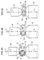
- FIGs. 3A to 3C An exemplary fusing work is illustrated in FIGs. 3A to 3C.
- This work provides electrical and physical connections between a covered wire 10 and a strip-like terminal 12 made of e.g., copper or copper alloy.
- a workpiece is inserted between a pair of (e.g., upper and lower) electrodes 14 and 16, the workpiece consisting of the terminal 12 and the covered wire 10 embraced in a hooked portion or a bent portion 12a of the terminal 12.
- the undersurface of the terminal hooked portion 12a is carried by the lower electrode 16 at a fixed position, with the upper electrode 14 abutting against the top surface of the terminal hooked portion 12a so that the latter is pressed downward with a predetermined pressurizing force F by a pressure device not shown.
- a predetermined voltage is applied to the two electrodes 14 and 16 by a power supply apparatus not shown.
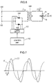
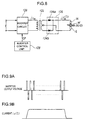
- FIG. 6 illustrates a circuit configuration of a single-phase AC power supply apparatus that has hitherto been used for the fusing work as described above.
- FIG. 7 illustrates waveforms of the voltage and current delivered from the power supply apparatus.
- a single-phase AC voltage V of a commercial frequency fed to input terminals 100 and 102 is applied to a primary coil of a step-down transformer 108 by way of a contactor that is comprised of a pair of thyristors 104 and 106.
- An AC induced electromotive force (secondary voltage) generated at the secondary coil of the transformer 108 is applied through the secondary conductor and the electrodes 14 and 16 to the workpiece W (10, 12) so as to allow a secondary current i 2 having a larger current value than that of a primary current i 1 to flow as the fusing current I through the secondary circuit.
- the magnitude (effective value) of the fusing current I (i 2 ) is determined depending on a conduction angle. Due to the presence of a substantially fixed relation between a firing angle and the conduction angle, it may be said that the magnitude depends on the firing angle.
- This power supply apparatus provides a control of firing angles (firing timings) ⁇ of the thyristors 104 and 106 by way of a firing circuit 112, to thereby control the effective value of the fusing current I (i 2 ).
- FIG. 8 illustrates a configuration of a DC inverter power supply apparatus that has hitherto been used in the fusing work.
- FIGs. 9A and 9B depict waveforms of the voltage and current output from the power supply apparatus.
- This power supply apparatus comprises an inverter circuit 120 to which a DC voltage E is applied at a predetermined voltage level by a rectifying circuit not shown.
- the inverter circuit 120 includes switching elements and serves to issue high-frequency AC pulses in such a manner as to chop up the DC input voltage E at a high-frequency switching in response to a control pulse CP from a inverter control unit 128.
- the AC pulses output from the inverter circuit 120 are fed to a primary coil of a step-down transformer 122 so that AC pulses similar to those at primary side are acquired in the secondary coil.
- the secondary pulsed alternating current is converted into a direct current by a rectifying circuit 126 consisting of a pair of diodes 124a and 124b, with the secondary direct current i 2 being fed as a fusing current I to the workpiece W (10, 12) by way of the electrodes 14 and 16.
- the ratio is small of the effective current-supplying time (the time during which current actually flows) to the gross current-supplying time, so that a current peak value needs to be increased in each current-supplying cycle if it is desired to supply a sufficient thermal energy for the fusing work.
- the increased current peak value tends to result in an increased instantaneous peak value of Joule heat generated in the workpiece, which may possibly cause undesirable deformations or damages as a result of heat shock to which the workpiece W may be subjected.
- the bend of the hooked portion 12a of the terminal 12 may crack in the vicinity of its top due to the heat shock.
- the ratio of the effective current-supplying time is large and its heat generating efficiency is high, so that a sufficient thermal energy can be supplied to the workpiece even at a relatively low current peak value, and thus any heat shock can be suppressed.
- this method is problematic in that since the fusing current I can flow between the two electrodes only in the same direction (polarity), the amount of heat generation may differ from place to place due to Peltier effect appearing between the electrodes 14, 16 and the workpiece W, whereupon the deformations and wears at the extremities of the electrodes are apt to concentrate in one electrode (typically, in the electrode 14 at positive side), which may result in a cumbersome maintenance and a rise in cost.
- the present invention was conceived in view of the above problems. It is therefore the object of the present invention to provide a fusing processing method capable of preventing any heat shock on a workpiece to improve the work quality and evening out the wears and degradations of the electrodes to improve the maintenance (workability, costs).
- a method of fusing a workpiece in which a pair of electrodes are pressed against the workpiece while simultaneously a current flows through the pair of electrodes to the workpiece to generate Joule heat comprising the steps of converting an AC voltage of a commercial frequency into a DC voltage by means of a rectifying circuit; converting the DC voltage output from the rectifying circuit, into a pulsed voltage of a high frequency by means of an inverter; passing the high-frequency pulsed voltage output from the inverter through a transformer, to apply it via the pair of electrodes to the workpiece without any rectification at secondary side of the transformer; and segmenting a current-supplying time for a single fusing processing into a plurality of current-supplying periods, to output the high-frequency pulses with one polarity from the inverter in odd-numbered current-supplying periods, but to output the high-frequency pulses with the other polarity from the inverter in even-numbered current
- the inverter allows a high-frequency waveform-controlled current to flow between two electrodes in each current-supplying period, whereby it is possible to achieve a high heat generating efficiency and hence to supply a sufficient heat energy to the workpiece even with a relatively low current peak value. This prevents the workpiece from being subjected to any heat shocks, enabling a stabilized fusing quality to be acquired.
- the polarity (direction) of current flowing between the two electrodes during the current-supplying time is inverted for each current-supplying period so that Peltier effect appearing between the electrodes and the workpiece is cancelled out or evened out and the amount of heat generation is also uniformed, thereby preventing deformations and wears at the electrode extremities from concentrating in one electrode, to ensure a fine finish in the fusing processing.
- FIG. 1 FIGs. 2A and 2B and FIGs. 3A to 3C which illustrate one embodiment thereof.
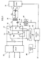
- FIG. 1 shows a circuit configuration of a power supply apparatus for carrying out a fusing processing method in accordance with the present invention.
- the power supply apparatus comprises an inverter generally designated at 22 which includes four transistor switching elements 24, 26, 28 and 30 in the form of, e.g., GTRs (giant transistors) or IGBTs (insulated gate bipolar transistors).
- GTRs giant transistors
- IGBTs insulated gate bipolar transistors
- a first set of (positive side) switching elements 24 and 28 are subjected at one time to a switching (on/off) control at a predetermined inverter frequency (e.g., 10 kHz) in response to a first inverter control signal Fa from a drive circuit 32
- a second set of (negative side) switching elements 26 and 30 are subjected at one time to a switching control at the inverter frequency in response to a second inverter control signal Fb from the drive circuit 32.
- the inverter 22 has input terminals (La, Lb) connected to output terminals of a rectifying circuit 20 and has output terminals (Ma, Mb) connected to ends of a primary coil of a step-down transformer 34.
- the two electrodes 14 and 16 are positioned away from (e.g., confronting) each other and are brought into pressure contact with workpieces W (10 and 12) by a pressurization force from a pressure device 36.
- the rectifying circuit 20 is a three-phase rectifier consisting of e.g., six (6) diodes that are three-phase bridge connected to one another.
- the rectifying circuit 20 converts a three-phase AC voltage at a commercial frequency from a three-phase AC power supply terminal (U, V, W), into a DC voltage.
- the DC voltage output from the rectifying circuit 20 is fed via a smoothing capacitor 21 to the inverter 22.
- a current sensor 38 in the form of, e.g., a current transformer is attached to a conductor extending between the output terminal of the inverter 22 and the primary coil of the transformer 34.
- the current sensor 38 issues a current detection signal ⁇ I 1 ⁇ indicative of an instantaneous value of a primary current i 1 having a waveform similar to that of a secondary current i 2 (fusing current I) which passes through the secondary circuit.
- a current measuring circuit 40 figures out, as a current measured value [I 1 ], an effective value or average value of the current i 1 on the basis of the current detection signal ⁇ I 1 ⁇ from the current sensor 38 and feeds the thus obtained current measured value [I 1 ] to a control unit 42.
- the control unit 42 is comprised of a microcomputer that includes a CPU, a ROM (program memory), a RAM (data memory), a clock circuit and an interface circuit, to provide all controls effected within the apparatus, for example, pressurization control and current control in the fusing processing, and their sequence controls, management of setting entries and registrations associated with set values for various conditions, and output control of measured values and judged values, etc.
- the fusing processing is initiated in response to a start signal ST from an external apparatus not shown.
- An entry unit 44 is comprised of entry devices such as a keyboard and a mouse, for use in setting entries of various conditions for fusing processing.
- Major conditions set and entered in this embodiment include a current-supplying time T G , a current-supplying period T A , and a current value I C for constant-current control.
- the current-supplying time T G is a gross current-supplying time from the initiation of fusing current supply to the termination thereof, which can be defined as the number of cycles that is equal to the integer multiples or even multiples of the current-supplying period T A that is a half cycle.
- the current-supplying period T A is a single independent current-supplying period during which the inverter 22 performs switching actions in a continuous manner at positive side or negative side, which can be defined as a period corresponding to a half cycle at the commercial frequency (50 Hz or 60 Hz) for example.
- the current value I C for constant-current control is a reference value that is used when a constant-current control is provided after the rise of current in each current-supplying period T A .
- this embodiment also allows a workpiece W to be inserted between the upper electrode 14 and the lower electrode 16, the workpiece W consisting of a terminal 12 and a covered wire 10 placed inside of a hooked portion 12a of the terminal 12.
- the lover electrode 16 carries the undersurface of the terminal hooked portion 12a at a fixed position, while simultaneously the upper electrode 14 is abutted against the top surface of the terminal hooked portion 12a so that the pressure device 36 can press the workpiece W downward with a predetermined pressurization force F.
- the current supply is initiated.
- the control unit 42 of the power supply apparatus provides a current-supplying sequence control.
- the control unit 42 allows continuous switching actions of the first set of (positive side) switching elements (24, 28) at an inverter frequency, with the second set of (negative side) switching elements (26, 30) remaining OFF.
- the control unit 42 allows continuous switching actions of the second set of (negative side) switching elements (26, 30) at the inverter frequency, with the first set of (positive side) switching elements (24, 28) remaining OFF.
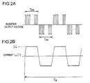
- the secondary circuit of the power supply apparatus allows a secondary current i 2 , namely a fusing current I having a substantially trapezoidal current waveform to flow in the positive direction in the odd-numbered current-supplying periods T AO , but to flow in the negative direction in the even-numbered current-supplying periods T AE .
- the control unit 42 uses as a feedback signal a current measured value [I 1 ] from the current measuring circuit 40, to cause the current value at the upper side of the trapezoidal current waveform to coincide with a set value I C by means of a PWM (pulse-width modulation) control for example.
- PWM pulse-width modulation
- each current-supplying period T A the fusing current I having a trapezoidal current waveform flows between the electrodes 14 and 16, whereupon a higher heating efficiency is achieved so that a sufficient thermal energy can be supplied to the workpiece W even at a relatively low current peak value I C .
- Joule heat sufficient to melt an insulator 10a of the covered wire 10 can be generated while preventing an occurrence of any heat shock at the workpiece W, in particular, at the terminal hooked portion 12a.
- the current I flows between the two electrodes 14 and 16 through a conductor 10b of the covered wire 10 as shown in FIG. 3C, to generate Joule heat at both the terminal 12 and the covered wire 10.
- This Joule heat and the pressurization force F from the pressure device 36 in cooperation, cause the terminal hooked portion 12a and the covered wire conductor 10b to be integrally pressure welded or pressure squashed for crimping.
- the control unit 42 brings the inverter 22 to a complete halt to terminate the current supply and, at a predetermined timing, cancels the pressurization force F applied by the pressure device 36.
- the fusing processing method of the present invention is applicable by way of example to a joint between an armature winding and a commutator of a DC motor as illustrated in FIG. 4 and FIGs. 5A and 5B.
- Ends 54i and 54j of insulated coils constituting the armature winding are received in a slot 60a in each slot block of a commutator 52 rigidly secured to a motor shaft 50, and the pressurization and current supply are carried out by means of the electrodes 14 and 16.
- current I does not flow through the coil ends 54i and 54j, bypassing the slot 60a since the coil ends 54i and 54j are coated with an insulator.
- the electrode 14 and the slot 60a generate a heat by the action of Joule heat, so that the resultant heat melts the insulating coatings of the coil ends 54i and 54j to cause the coil conductors to be exposed.
- the current I can flow through the coil conductors of the coil ends 54i and 54j, allowing the coil ends 54i and 54j to generate a heat by the action of Joule heat.
- the thus heat-generating coil ends 54i and 54j fuse as illustrated in FIGs. 5A and 5B under the pressurization force F from the pressure device 36, to be crimped to a terminal portion 60.
- this embodiment allows the polarity (direction) of the fusing current I flowing between the two electrodes 14 and 16 during the current-supplying time T G to be inverted at a certain cycle (T A ), Peltier effect appearing between the electrodes 14, 16 and the workpiece W is cancelled out or evened out, so that deformations or wears at the electrode extremities are prevented from being localized toward one side, to thereby reduce the number of times of replacement or maintenance of both the electrodes 14 and 16. Furthermore, due to the less degree of deformations or wears at the electrode extremities in addition to the absence of the heat shock as described above, a stabilized fusing processing is ensured and an improved work quality is achieved.
- the three-phase alternating current of the commercial frequency is converted into a direct current for the supply to the inverter 22
- a single-phase alternating current of the commercial frequency may be converted into a direct current.
- the circuit configuration of the inverter 22 is also a mere example, and various modifications would be possible.
- the current waveform in each current-supplying period T A is not limited to the trapezoidal waveform as in the above embodiment, but instead any arbitrary current waveform may be provided by use of PWM control for example.
- the fusing processing of FIGs. 3A to 3C is also a mere example, and the present invention would be applicable to other various fusing processing.
- any heat shock which may be applied to the workpiece is prevented to improve the work quality, and wear and degradation of the electrodes is evened out to improve the maintenance.
Landscapes
- Engineering & Computer Science (AREA)
- Mechanical Engineering (AREA)
- Manufacturing & Machinery (AREA)
- Inverter Devices (AREA)
- Generation Of Surge Voltage And Current (AREA)
- Wire Processing (AREA)
- Manufacturing Of Electrical Connectors (AREA)
- Pressure Welding/Diffusion-Bonding (AREA)
- Lining Or Joining Of Plastics Or The Like (AREA)
- General Induction Heating (AREA)
Applications Claiming Priority (2)
| Application Number | Priority Date | Filing Date | Title |
|---|---|---|---|
| JP11141023A JP2000326026A (ja) | 1999-05-21 | 1999-05-21 | ヒュージング加工方法 |
| JP14102399 | 1999-05-21 |
Publications (2)
| Publication Number | Publication Date |
|---|---|
| EP1055477A2 true EP1055477A2 (de) | 2000-11-29 |
| EP1055477A3 EP1055477A3 (de) | 2002-01-09 |
Family
ID=15282422
Family Applications (1)
| Application Number | Title | Priority Date | Filing Date |
|---|---|---|---|
| EP00304105A Withdrawn EP1055477A3 (de) | 1999-05-21 | 2000-05-16 | Schmelzverbindungsverfahren |
Country Status (5)
| Country | Link |
|---|---|
| US (1) | US6486456B1 (de) |
| EP (1) | EP1055477A3 (de) |
| JP (1) | JP2000326026A (de) |
| KR (1) | KR20000077325A (de) |
| CN (1) | CN1274630A (de) |
Cited By (1)
| Publication number | Priority date | Publication date | Assignee | Title |
|---|---|---|---|---|
| EP1110655A3 (de) * | 1999-12-22 | 2002-08-07 | Miyachi Technos Corporation | Wiederaufschmelzvorrichtung |
Families Citing this family (9)
| Publication number | Priority date | Publication date | Assignee | Title |
|---|---|---|---|---|
| JP2002224841A (ja) * | 2001-02-02 | 2002-08-13 | Honda Motor Co Ltd | 接続端子の接合方法 |
| JP4319586B2 (ja) * | 2004-06-23 | 2009-08-26 | 株式会社ダイヘン | 交流パルスアーク溶接方法 |
| US7964829B2 (en) * | 2006-12-20 | 2011-06-21 | Tyco Healthcare Group Lp | Apparatus and method for making bag assembly |
| KR101497152B1 (ko) * | 2008-12-16 | 2015-03-03 | 두산인프라코어 주식회사 | 방전가공기의 직류전압공급장치 |
| US8151851B2 (en) | 2009-06-17 | 2012-04-10 | Tyco Healthcare Group Lp | Apparatus for making bag assembly and method thereof |
| US8502121B2 (en) * | 2009-06-17 | 2013-08-06 | Covidien Lp | Radiofrequency welding apparatus |
| US8398572B2 (en) | 2010-09-21 | 2013-03-19 | Covidien Lp | Bladder tube connection |
| WO2014011272A2 (en) * | 2012-04-11 | 2014-01-16 | Brookhaven Science Associates, Llc | Radio frequency-assisted fast superconducting switch |
| CN110315170A (zh) * | 2019-05-31 | 2019-10-11 | 广汽乘用车有限公司 | 一种用于焊装车间的中频交流焊接系统及方法 |
Family Cites Families (9)
| Publication number | Priority date | Publication date | Assignee | Title |
|---|---|---|---|---|
| JPS59232678A (ja) * | 1983-06-16 | 1984-12-27 | Miyachi Denshi Kk | ヒユ−ジング装置の電源制御方法 |
| US4766282A (en) * | 1986-09-18 | 1988-08-23 | Joyal Products, Inc. | Fusing apparatus and method with electrode changing |
| IT1242893B (it) * | 1990-12-27 | 1994-05-18 | Cefin Spa | Dispositivo elettronico per la gestione ed il controllo dell'energia elettrica di alimentazione per saldatura a resistenza, in particolare di corpi di scatole metalliche. |
| US5300753A (en) * | 1992-06-25 | 1994-04-05 | Axis Usa, Incorporated | Methods and apparatus for fusing electrical conductors |
| JP2617668B2 (ja) * | 1992-12-24 | 1997-06-04 | 本田技研工業株式会社 | 直流抵抗溶接機の溶接電流制御方法 |
| DE69515083T2 (de) * | 1994-05-27 | 2000-10-12 | Toshiba Kawasaki Kk | Steueranlage für Widerstandsschweissmaschine |
| EP0835713A1 (de) * | 1996-09-11 | 1998-04-15 | Miyachi Technos Corporation | Verfahren und Gerät zum Steuern des Widerstandsschweissens. |
| JPH11285852A (ja) * | 1998-04-02 | 1999-10-19 | Miyachi Technos Corp | 抵抗溶接制御装置 |
| JP2000052051A (ja) * | 1998-08-10 | 2000-02-22 | Miyachi Technos Corp | インバータ式抵抗溶接制御装置 |
-
1999
- 1999-05-21 JP JP11141023A patent/JP2000326026A/ja active Pending
-
2000
- 2000-05-16 EP EP00304105A patent/EP1055477A3/de not_active Withdrawn
- 2000-05-18 KR KR1020000026738A patent/KR20000077325A/ko not_active Withdrawn
- 2000-05-18 US US09/573,255 patent/US6486456B1/en not_active Expired - Fee Related
- 2000-05-19 CN CN00108945A patent/CN1274630A/zh active Pending
Cited By (1)
| Publication number | Priority date | Publication date | Assignee | Title |
|---|---|---|---|---|
| EP1110655A3 (de) * | 1999-12-22 | 2002-08-07 | Miyachi Technos Corporation | Wiederaufschmelzvorrichtung |
Also Published As
| Publication number | Publication date |
|---|---|
| JP2000326026A (ja) | 2000-11-28 |
| US6486456B1 (en) | 2002-11-26 |
| CN1274630A (zh) | 2000-11-29 |
| EP1055477A3 (de) | 2002-01-09 |
| KR20000077325A (ko) | 2000-12-26 |
Similar Documents
| Publication | Publication Date | Title |
|---|---|---|
| KR100727377B1 (ko) | 금속부재 접합방법 및 리플로 납땜방법 | |
| US6486456B1 (en) | Fusing processing method | |
| US6046424A (en) | Resistance welding control apparatus | |
| CN1272137C (zh) | 被覆线用电阻焊接装置 | |
| US6326580B1 (en) | Joining apparatus | |
| US6423950B2 (en) | Reflow soldering apparatus | |
| CA2132120A1 (en) | Fusing methods and apparatus for use in making dynamo-electric machines | |
| JP3369345B2 (ja) | スタッド溶接機 | |
| JPH1085947A (ja) | 抵抗溶接制御方法及び装置 | |
| KR100782366B1 (ko) | 금속부재접합방법 및 교류파형 인버터식 전원장치 | |
| JP3691797B2 (ja) | 溶接電源 | |
| JP2003080372A (ja) | 被覆線用接合装置 | |
| JP2006187791A (ja) | インバータ式抵抗溶接電源装置 | |
| KR100227714B1 (ko) | 편향 코일의 통전 가열 및 용착 장치 | |
| JPH10128551A (ja) | 抵抗溶接方法及び装置 | |
| JP2001275224A (ja) | 接合装置 | |
| TW458832B (en) | Resistance welder | |
| JPH09277066A (ja) | トランジスタ方式溶接電源装置 | |
| JP2507295B2 (ja) | 抵抗溶接機 | |
| JP2023076110A (ja) | 抵抗溶接装置 | |
| JPH065027Y2 (ja) | インバータ式抵抗溶接機の電源装置 | |
| JP2507295C (de) | ||
| KR19980032384A (ko) | 저항용접 제어방법 및 장치 |
Legal Events
| Date | Code | Title | Description |
|---|---|---|---|
| PUAI | Public reference made under article 153(3) epc to a published international application that has entered the european phase |
Free format text: ORIGINAL CODE: 0009012 |
|
| AK | Designated contracting states |
Kind code of ref document: A2 Designated state(s): AT BE CH CY DE DK ES FI FR GB GR IE IT LI LU MC NL PT SE Kind code of ref document: A2 Designated state(s): DE FR GB IT NL |
|
| AX | Request for extension of the european patent |
Free format text: AL;LT;LV;MK;RO;SI |
|
| PUAL | Search report despatched |
Free format text: ORIGINAL CODE: 0009013 |
|
| AK | Designated contracting states |
Kind code of ref document: A3 Designated state(s): AT BE CH CY DE DK ES FI FR GB GR IE IT LI LU MC NL PT SE |
|
| AX | Request for extension of the european patent |
Free format text: AL;LT;LV;MK;RO;SI |
|
| 17P | Request for examination filed |
Effective date: 20020708 |
|
| AKX | Designation fees paid |
Free format text: DE FR GB IT NL |
|
| R17P | Request for examination filed (corrected) |
Effective date: 20020709 |
|
| 17Q | First examination report despatched |
Effective date: 20020909 |
|
| STAA | Information on the status of an ep patent application or granted ep patent |
Free format text: STATUS: THE APPLICATION IS DEEMED TO BE WITHDRAWN |
|
| 18D | Application deemed to be withdrawn |
Effective date: 20030604 |