EP1055449B1 - Verfahren zur Überwachung der Funktion eines Systems zur Abgasnachbehandlung - Google Patents
Verfahren zur Überwachung der Funktion eines Systems zur Abgasnachbehandlung Download PDFInfo
- Publication number
- EP1055449B1 EP1055449B1 EP00110872A EP00110872A EP1055449B1 EP 1055449 B1 EP1055449 B1 EP 1055449B1 EP 00110872 A EP00110872 A EP 00110872A EP 00110872 A EP00110872 A EP 00110872A EP 1055449 B1 EP1055449 B1 EP 1055449B1
- Authority
- EP
- European Patent Office
- Prior art keywords
- catalytic converter
- temperature
- akt
- exhaust gas
- concentration
- Prior art date
- Legal status (The legal status is an assumption and is not a legal conclusion. Google has not performed a legal analysis and makes no representation as to the accuracy of the status listed.)
- Expired - Lifetime
Links
Images

Classifications
-
- F—MECHANICAL ENGINEERING; LIGHTING; HEATING; WEAPONS; BLASTING
- F01—MACHINES OR ENGINES IN GENERAL; ENGINE PLANTS IN GENERAL; STEAM ENGINES
- F01N—GAS-FLOW SILENCERS OR EXHAUST APPARATUS FOR MACHINES OR ENGINES IN GENERAL; GAS-FLOW SILENCERS OR EXHAUST APPARATUS FOR INTERNAL-COMBUSTION ENGINES
- F01N3/00—Exhaust or silencing apparatus having means for purifying, rendering innocuous, or otherwise treating exhaust
- F01N3/08—Exhaust or silencing apparatus having means for purifying, rendering innocuous, or otherwise treating exhaust for rendering innocuous
- F01N3/10—Exhaust or silencing apparatus having means for purifying, rendering innocuous, or otherwise treating exhaust for rendering innocuous by thermal or catalytic conversion of noxious components of exhaust
- F01N3/18—Exhaust or silencing apparatus having means for purifying, rendering innocuous, or otherwise treating exhaust for rendering innocuous by thermal or catalytic conversion of noxious components of exhaust characterised by methods of operation; Control
- F01N3/20—Exhaust or silencing apparatus having means for purifying, rendering innocuous, or otherwise treating exhaust for rendering innocuous by thermal or catalytic conversion of noxious components of exhaust characterised by methods of operation; Control specially adapted for catalytic conversion
- F01N3/206—Adding periodically or continuously substances to exhaust gases for promoting purification, e.g. catalytic material in liquid form, NOx reducing agents
- F01N3/2066—Selective catalytic reduction [SCR]
-
- B—PERFORMING OPERATIONS; TRANSPORTING
- B01—PHYSICAL OR CHEMICAL PROCESSES OR APPARATUS IN GENERAL
- B01D—SEPARATION
- B01D53/00—Separation of gases or vapours; Recovering vapours of volatile solvents from gases; Chemical or biological purification of waste gases, e.g. engine exhaust gases, smoke, fumes, flue gases, aerosols
- B01D53/34—Chemical or biological purification of waste gases
- B01D53/92—Chemical or biological purification of waste gases of engine exhaust gases
- B01D53/94—Chemical or biological purification of waste gases of engine exhaust gases by catalytic processes
- B01D53/9495—Controlling the catalytic process
-
- F—MECHANICAL ENGINEERING; LIGHTING; HEATING; WEAPONS; BLASTING
- F01—MACHINES OR ENGINES IN GENERAL; ENGINE PLANTS IN GENERAL; STEAM ENGINES
- F01N—GAS-FLOW SILENCERS OR EXHAUST APPARATUS FOR MACHINES OR ENGINES IN GENERAL; GAS-FLOW SILENCERS OR EXHAUST APPARATUS FOR INTERNAL-COMBUSTION ENGINES
- F01N11/00—Monitoring or diagnostic devices for exhaust-gas treatment apparatus
- F01N11/002—Monitoring or diagnostic devices for exhaust-gas treatment apparatus the diagnostic devices measuring or estimating temperature or pressure in, or downstream of the exhaust apparatus
-
- F—MECHANICAL ENGINEERING; LIGHTING; HEATING; WEAPONS; BLASTING
- F01—MACHINES OR ENGINES IN GENERAL; ENGINE PLANTS IN GENERAL; STEAM ENGINES
- F01N—GAS-FLOW SILENCERS OR EXHAUST APPARATUS FOR MACHINES OR ENGINES IN GENERAL; GAS-FLOW SILENCERS OR EXHAUST APPARATUS FOR INTERNAL-COMBUSTION ENGINES
- F01N11/00—Monitoring or diagnostic devices for exhaust-gas treatment apparatus
- F01N11/007—Monitoring or diagnostic devices for exhaust-gas treatment apparatus the diagnostic devices measuring oxygen or air concentration downstream of the exhaust apparatus
-
- F—MECHANICAL ENGINEERING; LIGHTING; HEATING; WEAPONS; BLASTING
- F01—MACHINES OR ENGINES IN GENERAL; ENGINE PLANTS IN GENERAL; STEAM ENGINES
- F01N—GAS-FLOW SILENCERS OR EXHAUST APPARATUS FOR MACHINES OR ENGINES IN GENERAL; GAS-FLOW SILENCERS OR EXHAUST APPARATUS FOR INTERNAL-COMBUSTION ENGINES
- F01N2550/00—Monitoring or diagnosing the deterioration of exhaust systems
- F01N2550/02—Catalytic activity of catalytic converters
-
- F—MECHANICAL ENGINEERING; LIGHTING; HEATING; WEAPONS; BLASTING
- F01—MACHINES OR ENGINES IN GENERAL; ENGINE PLANTS IN GENERAL; STEAM ENGINES
- F01N—GAS-FLOW SILENCERS OR EXHAUST APPARATUS FOR MACHINES OR ENGINES IN GENERAL; GAS-FLOW SILENCERS OR EXHAUST APPARATUS FOR INTERNAL-COMBUSTION ENGINES
- F01N2550/00—Monitoring or diagnosing the deterioration of exhaust systems
- F01N2550/05—Systems for adding substances into exhaust
-
- F—MECHANICAL ENGINEERING; LIGHTING; HEATING; WEAPONS; BLASTING
- F01—MACHINES OR ENGINES IN GENERAL; ENGINE PLANTS IN GENERAL; STEAM ENGINES
- F01N—GAS-FLOW SILENCERS OR EXHAUST APPARATUS FOR MACHINES OR ENGINES IN GENERAL; GAS-FLOW SILENCERS OR EXHAUST APPARATUS FOR INTERNAL-COMBUSTION ENGINES
- F01N2610/00—Adding substances to exhaust gases
- F01N2610/14—Arrangements for the supply of substances, e.g. conduits
- F01N2610/1473—Overflow or return means for the substances, e.g. conduits or valves for the return path
-
- Y—GENERAL TAGGING OF NEW TECHNOLOGICAL DEVELOPMENTS; GENERAL TAGGING OF CROSS-SECTIONAL TECHNOLOGIES SPANNING OVER SEVERAL SECTIONS OF THE IPC; TECHNICAL SUBJECTS COVERED BY FORMER USPC CROSS-REFERENCE ART COLLECTIONS [XRACs] AND DIGESTS
- Y02—TECHNOLOGIES OR APPLICATIONS FOR MITIGATION OR ADAPTATION AGAINST CLIMATE CHANGE
- Y02T—CLIMATE CHANGE MITIGATION TECHNOLOGIES RELATED TO TRANSPORTATION
- Y02T10/00—Road transport of goods or passengers
- Y02T10/10—Internal combustion engine [ICE] based vehicles
- Y02T10/12—Improving ICE efficiencies
-
- Y—GENERAL TAGGING OF NEW TECHNOLOGICAL DEVELOPMENTS; GENERAL TAGGING OF CROSS-SECTIONAL TECHNOLOGIES SPANNING OVER SEVERAL SECTIONS OF THE IPC; TECHNICAL SUBJECTS COVERED BY FORMER USPC CROSS-REFERENCE ART COLLECTIONS [XRACs] AND DIGESTS
- Y02—TECHNOLOGIES OR APPLICATIONS FOR MITIGATION OR ADAPTATION AGAINST CLIMATE CHANGE
- Y02T—CLIMATE CHANGE MITIGATION TECHNOLOGIES RELATED TO TRANSPORTATION
- Y02T10/00—Road transport of goods or passengers
- Y02T10/10—Internal combustion engine [ICE] based vehicles
- Y02T10/40—Engine management systems
Definitions
- the invention relates to the exhaust aftertreatment in internal combustion engines.
- the problem of exhaust aftertreatment is already in a comprehensive overview in the Bosch / Automotive Handbook 22nd Edition (ISBN 3-18-419122-2) in the chapter “Exhaust gas from gasoline engines” (p.486ff) explained.
- Diesel / Automotive Handbook 22nd Edition ISBN 3-18-419122-2
- Exhaust gas from gasoline engines p.486ff
- the nitric oxide is colorless, odorless and tasteless and slowly converts to NO 2 in the air.
- This NO 2 is in pure form a pungent, poisonous gas, so that it can irritate the mucous membranes at higher concentrations.
- NO and NO 2 are commonly referred to collectively as nitrogen oxides NOx.
- Hydrocarbons are present in great variety in the exhaust gas and form oxidants in the presence of nitrogen oxide and sunlight.
- This exhaust gas mixture enters the exhaust gas line, where it is usually first introduced into an oxidation catalyst which oxidizes the hydrocarbons to carbon dioxide and water and the carbon monoxide to carbon dioxide. At the same time, nitrogen monoxide NO is also oxidized to nitrogen dioxide.
- a number of measures for influencing the exhaust gas composition are known, these measures can be divided into motor measures and exhaust aftertreatment measures substantially. Since the present invention relates to the measures for aftertreatment, the motor measures should not be further explained here.
- the possibilities of exhaust aftertreatment include the thermal Afterburning and catalytic afterburning.
- the catalysts used in the catalytic afterburning usually consist of a carrier material with active coating, which favors the chemical reaction, in particular the harmful constituents of the exhaust gas.
- so-called Vollextrudationskatalysatoren can be used. Since the efficiency of the catalyst depends essentially on its operating temperature, catalysts are often installed close to the engine, since so the time is shortened until reaching the operating temperature, whereby an optimal efficiency is achieved quickly.
- oxidation catalysts which essentially oxidize the carbon monoxide CO and the hydrocarbons HC is known. They are operated either by lean engine operation or by additional air injection with excess air or in the superstoichiometric diesel exhaust gas so that carbon monoxide and the HC components are oxidized. Furthermore, reduction catalysts are known which reduce the nitrogen oxides in the exhaust gas. The series connection of oxidation and reduction catalyst with an air injection between the two catalysts has the advantage that both NOx and HC and CO can be degraded.
- the inventive method for monitoring the function of a system for exhaust aftertreatment with the features of the main claim has over the known the advantage that when using a series circuit of oxidation catalyst and reduction catalyst in the exhaust line, the function and thus the reliability of each catalyst monitors itself or both in combination can be.
- the function of the oxidation catalyst is permanently affected by excessive thermal stress at high exhaust gas temperatures, there is a thermal aging. Decisive for the extent of aging are the frequency and the level of critical temperatures above a reference value. By adding up the temperatures above the reference value, a statement about the thermal load of the oxidation catalyst is made.
- the detection of the NOx concentration or the NOx and NH 3 concentration in the exhaust gas after the reducing agent catalyst and the comparison of the NOx concentration at a defined operating point of the internal combustion engine with a stored control value of the NOx content has the advantage that very quickly a statement is possible via the exhaust gas composition and when recognizing an increase in the NOx concentration, an error message for the driver takes place.
- an error message for the driver may preferably be provided in the instrument cluster optical and / or acoustic information.
- a corresponding error entry in the control unit can take place, which can then be read out in the workshop.
- a more detailed information such as which catalyst has caused the error message or how high the maximum temperature in the Oxikat or the NOx or. NH 3 concentration after the reduction catalyst was to be stored.
- Fig. 1 shows the block diagram of the output strand of an internal combustion engine.
- the reference numeral 10 the engine block is shown.
- the resulting during combustion in the individual cylinders of the engine block 10 exhaust gas is discharged via the exhaust line 11.
- an oxidation catalyst (Oxi-Kat) 12 In the exhaust line 11 is located in the immediate vicinity of the engine block 10, an oxidation catalyst (Oxi-Kat) 12, wherein a first temperature sensor 13 is disposed in the exhaust line 11 in front of the oxidation catalyst 12 and the temperature clock-v detected before the oxidation catalyst 12 and wherein a second temperature sensor 14 in the exhaust line 11 after the oxidation catalyst detects the temperature clock-n after the oxidation catalyst 12.
- a reduction catalyst 20 In series connection to the oxidation catalyst 12 is a reduction catalyst 20, wherein before the reduction catalyst, a temperature sensor 18 and after the reduction catalyst, a temperature sensor 19 is arranged. Also in front of the reduction catalyst 20, a first exhaust gas sensor 21 for detecting the raw emission of nitrogen oxides E-NOx is arranged. A second exhaust gas sensor 22 is disposed in the exhaust line after the reduction catalyst and detects the NOx or NOx / NH3 concentration of the exhaust gas.
- the exhaust line 11 is further associated with a reducing agent tank 15, which is added via a reducing agent addition 16, which is arranged in the exhaust line 11 between the oxidation catalyst 12 and the reduction catalyst 20, the exhaust gas targeted reducing agent.
- a mixer 17 in the exhaust gas line 11 ensures homogeneous mixing of the exhaust gas with the reducing agent 15.
- the monitoring of the oxidation catalyst with a single temperature sensor, which may be arranged either before or after the oxidation catalyst.
- the current temperature is detected clock, here either the temperature of the temperature sensor 13 or the temperature of the temperature sensor 14 is determined before or after the oxidation catalyst.
- This detected current temperature clock is then compared in a query 26 with a predetermined reference value Tref (clock> Tref), this predetermined Refernzwert Tref is beauschbelgt possibly with engine operating variables and weighting factors, so, for example, at higher exhaust gas flow a stronger weighting of the critical temperature Tref respectively.
- step 27 If the current temperature value is greater than the predefinable temperature reference value (clock> Tref), then the Yes output of the query 26 to a step 27.
- a subsequent query 29 it is checked whether the calculated sum ⁇ Ü is greater than a predefinable limit value GW for the error display. If the query 29 ⁇ Ü> GW has been answered in the negative, the No output leads back to the beginning of the method at step 25, and the next temperature value is detected. On the other hand, if the query 29 was answered in the affirmative, that is to say that the sum ⁇ Ü formed is greater than the permissible limit value GW, an error information occurs in step 30.
- This error information can be made visually and / or acoustically.
- a corresponding error information can also be stored in the memory so that, if necessary, more accurate data about the error that occurred can then be read out at a workshop visit. It is conceivable, for example, to simultaneously store the operating point at which the elevated temperature was measured.
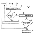
- FIG. 3 shows the method for checking the oxidation catalytic converter by utilizing the measured actual temperature values of two temperature sensors, a first temperature sensor 13 being arranged in the exhaust gas line 11 upstream of the oxidation catalytic converter and a second temperature sensor 14 in the exhaust gas line downstream of the oxidation catalytic converter.
- the first temperature sensor 13 before the oxidation catalyst takes into account in this case exhaust gas temperatures, which can cause thermal aging on the catalyst, while the temperature sensor 14 after the oxidation catalyst takes into account a possible burning off of soot and / or stored hydrocarbons in the oxidation catalyst.
- the burning of these substances can be triggered by an increase in the exhaust gas temperature after prolonged operation with low exhaust gas temperatures, which are below the operating temperature of the oxidation catalyst.
- Clock (w) f (clock-v; clock-n).
- the subsequent query 33 is analogous to the step 26 of FIG. 2, the comparison of these Mean gas temperature clock (gew) with a predefinable reference temperature Tref.
- the further steps or queries are carried out analogously to the flowchart of FIG. 2 and will not be explained separately here again.
- An essential difference of this method according to FIG. 3 for the method according to FIG. 2 is merely that a value for the catalyst mean temperature is determined from the temperatures before and after the oxidation catalyst and the further method steps are taken as a basis.
- step 34 exceeding the reference temperature in the query 33 means that in step 34, the sum of the exceedances is formed by respective addition of the last too high temperature values, while in the other case the last determined value for the catalyst means temperature is deleted in step 35.
- the sum ⁇ (clock (gew)) formed in step 34 is compared in the query 36 with a predefinable limit value GW. Depending on the result of the comparison, it is then either jumped to the beginning of the method or there is an error information in step 37.
- the reducing agent metering unit 16 shown in FIG. 1 adds to the exhaust gas after the oxidation catalyst 12 either an aqueous urea solution, a solid urea, an NH 3 -containing gas or an ammonia-forming substance.
- the nitrogen oxide concentration in defined operating points BP1 and BP2 is known. By comparing this expected nitric oxide concentration and the actually measured nitric oxide concentration, if the expected nitric oxide concentration is exceeded, a corresponding malfunction can be detected and error information output.
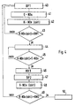
- FIG. 4 shows a flow chart for checking the functionality and the operation of the reduction catalytic converter.
- a defined operating point BP1 is present or the current operating point is determined.
- Each operating point, a NOx concentration in the exhaust gas can be assigned, these values are usually determined in the application and stored in a memory on a map.
- the raw emission of the engine E-NOx before the reduction catalyst is detected and measured in a further step 42, the current emission after the Reduktionslkatalysator K-NOx (akt).
- a query 43 checks whether the NOx concentration in the exhaust gas downstream of the reduction catalytic converter is greater than a predefinable control value KW1 (K-NOx (akt)> KW1). If this is not the case, then the no output of query 43 leads back to the beginning of the method for operation 40. However, if query 43 was answered with yes, ie the NOx content in the exhaust gas is greater than the predefinable control value KW1, then In a subsequent step 44, the addition of the reducing agent is adjusted. In the following query 45 it is checked whether the nitrogen oxide concentration downstream of the reduction catalyst K-NOx (akt) is approximately equal to the raw emission of the engine E-NOx. If this is not the case, the No output returns to step 44, where the NH3 dosage remains set.
- the metering of the reducing agent NH3 is in turn activated in a subsequent operation 46.
- a subsequent step 47 a defined operating point BP2 is awaited and then in step 48, the raw emission of nitrogen oxide of the engine E-NOx before the reduction catalyst and the current nitrogen oxide concentration after the reducing agent catalyst K-NOx (akt) measured again.
- the NOx concentration after the reducing agent catalyst is greater than a predetermined control value, takes place in Step 50 an error information. If no increased NOx concentration has been determined, the No output of query 49 returns to the beginning of the procedure.
- a query can be made at query 45 still a sensor. If NH3 dosing is not active, a comparison of the NOx sensors with values stored in the map is possible. Too large deviations of the gelled from the sensor value from the map is usually a sensor defect, which can also be detected so quickly. Furthermore, an indirect monitoring of the Oxikats is possible. Thus, in the case of a defective oxime, the NO x conversion proceeds at low temperatures, even though the reduction catalyst has not aged, since usually the reaction catalyst has a higher activity at low temperatures and upstream of the oxy-cat.
Landscapes
- Engineering & Computer Science (AREA)
- Chemical & Material Sciences (AREA)
- Chemical Kinetics & Catalysis (AREA)
- Combustion & Propulsion (AREA)
- Mechanical Engineering (AREA)
- General Engineering & Computer Science (AREA)
- Health & Medical Sciences (AREA)
- Environmental & Geological Engineering (AREA)
- Biomedical Technology (AREA)
- Analytical Chemistry (AREA)
- General Chemical & Material Sciences (AREA)
- Oil, Petroleum & Natural Gas (AREA)
- Toxicology (AREA)
- Exhaust Gas After Treatment (AREA)
- Exhaust Gas Treatment By Means Of Catalyst (AREA)
- Combined Controls Of Internal Combustion Engines (AREA)
Description
- Die Erfindung betrifft die Abgasnachbehandlung in Brennkraftmaschinen. Die Problematik der Abgasnachbehandlung ist bereits in einem umfassenden Überblick im Bosch/Kraftfahrtechnisches Taschenbuch 22. Auflage (ISBN 3-18-419122-2) in dem Kapitel "Abgase von Ottomotoren" (S.486ff) erläutert. Bei der Verbrennung des Kraftstoff-Luftgemisches in Brennkraftmaschinen entstehen eine Reihe von Verbrennungsprodukten. So entstehen neben den ungiftigen Hauptbestandteilen Stickstoff, Kohlendioxid und Wasserdampf des Abgases eine Reihe von weniger verträglichen Nebenbestandteilen. Als Nebenbestandteil sind im Abgas unter anderem Kohlenmonoxid (CO), Stickstoffmonoxid (NO), Stickstoffdioxid (NO2), Kohlenwasserstoffe (HC) und Feststoffe enthalten. Das Stickstoffmonoxid ist farb-, geruchs- und geschmacklos und wandelt sich in der Luft langsam in NO2 um. Dieses NO2 ist in reiner Form ein stechend riechendes, giftiges Gas, so daß es bei höherer Konzentration die Schleimhäute reizen kann. NO und NO2 werden üblicherweise zusammenfassend als Stickoxide NOx bezeichnet. Kohlenwasserstoffe sind in großer Vielfalt im Abgas enthalten und bilden in Anwesenheit von Stickoxid und Sonnenlicht Oxidanten. Dieses Abgasgemisch gelangt in den Abgasstrang, wo es in der Regel zunächst in einen Oxidationskatalysator eingeleitet wird, welcher die Kohlenwasserstoffe zu Kohlendioxid und Wasser und das Kohlenmonoxid zu Kohlendioxid aufoxidiert. Gleichzeitig wird auch Stickstoffmonoxid NO zu Stickstoffdioxid aufoxidiert wird.
- Zur Verminderung insbesondere schädlicher Anteile in dem Abgas sind eine Reihe von Maßnahmen zur Beeinflussung der Abgaszusammensetzung bekannt, wobei sich diese Maßnahmen im wesentlichen in motorische Maßnahmen und Abgasnachbehandlungsmaßnahmen einteilen lassen. Da die vorliegende Erfindung sich auf die Maßnahmen zur Nachbehandlung bezieht, sollen die motorischen Maßnahmen hier nicht weiter erläutert werden. Zu den Möglichkeiten der Abgasnachbehandlung zählen die thermische Nachverbrennung und die katalytische Nachverbrennung. Die bei der katalytischen Nachverbrennung eingesetzten Katalysatoren bestehen üblicherweise aus einem Trägermaterial mit aktiver Beschichtung, welche die chemische Umsetzung insbesondere der schädlichen Bestandteile des Abgases begünstigt. Alternativ können auch sogenannte Vollextrudationskatalysatoren eingesetzt werden. Da der Wirkungsgrad des Katalysators im wesentlichen von seiner Betriebstemperatur abhängt, werden Katalysatoren gern in Motornähe eingebaut, da so die Zeit bis zum Erreichen der Betriebstemperatur verkürzt ist, wodurch schnell ein optimaler Wirkungsgrad erreicht wird. Gleichzeitig hat der motornahe Einbau aber auch den Nachteil einer hohen thermischen Belastung des Katalysators. Fehlfunktionen des Motors wie beispielsweise Zündaussetzer beim Ottomotor können die Temperatur des Katalysators aufgrund der im Katalysator stattfindenden Umsetzung des nichtverbrannten Kraftstoffes so hoch ansteigen lassen, daß er durch Schmelzen des Trägermaterials zerstört wird. Dies wird in der Regel durch den Einsatz zuverlässiger und wartungsfreier Zündsysteme verhindert.
- Bekannt ist der Einsatz von Oxidationskatalysatoren, die im wesentlichen das Kohlenmonoxid CO und die Kohlenwasserstoffe HC oxidieren. Sie werden entweder durch mageren Motorbetrieb oder durch zusätzliche Lufteinblasung mit Luftüberschuß oder im überstöchiometrischen Dieselabgas so betrieben, daß Kohlenmonoxid und die HC-Bestandteile oxidiert werden. Es sind weiterhin Reduktionskatalysatoren bekannt, die die Stickoxide im Abgas reduzieren. Die Reihenschaltung von Oxidations- und Reduktionskatalysator mit einer Lufteinblasung zwischen beiden Katalysatoren hat den Vorteil, daß so sowohl NOx als auch HC und CO abgebaut werden können.
- Das Funktionsprinzip und die Arbeitsweise eines Reduktionsmittelkatalysators, sowie ein Verfahren und eine Einrichtung zur Dosierung eines Reduktionsmittels in ein stickoxidhaltiges Abgas zur Reduzierung dieser Bestandteile im nachgeordneten Reduktionskatalysator sind bereits aus der DE 43 15 278 A1 bekannt, so daß dies hier nicht im einzelnen erläutert werden soll.
- Das erfindungsgemäße Verfahren zur Überwachung der Funktion eines Systems zur Abgasnachbehandlung mit den Merkmalen des Hauptanspruchs hat gegenüber dem Bekannten den Vorteil, daß bei der Verwendung einer Reihenschaltung aus Oxidationskatalysator und Reduktionskatalysator im Abgasstrang die Funktion und damit die Zuverlässigkeit jedes Katalysators für sich oder beide in Kombination überwacht werden können. Die Funktion des Oxidationskatalysators wird durch eine übermäßige thermische Beanspruchung bei zu hohen Abgastemperaturen bleibend beeinträchtigt, es tritt eine thermische Alterung ein. Ausschlaggebend für das Ausmaß der Alterung sind die Häufigkeit und die Höhe der kritischen Temperaturen oberhalb eines Referenzwertes. Durch Aufsummierung der Temperaturen oberhalb des Referenzwertes wird eine Aussage zur thermischen Belastung des Oxidationskatalysators getroffen. Der Vergleich der so gebildeten Summe mit einem vorgebbaren Grenzwert, bei dessen Überschreitung eine Fehleranzeige erfolgt, ermöglicht es sehr schnell, den Fahrer optisch und/oder akustisch über den kritischen Zustand des Oxidationskatalysators zu informieren. Die Überprüfung des Reduktionskatalysators durch Erfassung der Stickoxid- (NOx) oder Ammoniak- (NH3) Werte nach dem Katalysator ermöglicht eine differenzierte Aussage über die Funktionsfähigkeit dieses Reduktionskatalysators oder der Reduktionsmitteldosiereinrichtung.
- Durch die in den abhängigen Ansprüchen aufgeführten Maßnahmen sind weitere vorteilhafte Ausgestaltungen des erfindungsgemäßen Verfahrens möglich.
- Das Vorsehen von zwei Temperatursensoren, wobei ein Temperatursensor vor dem Oxidationskatalysator und ein Temperatursensor nach dem Oxidationskatalysator angeordnet ist, hat den Vorteil, daß aufgrund des Vergleiches der Temperaturen vor und nach dem Oxidationskatalysator eine wesentlich genauere Aussage über die tatsächliche Temperatur im Oxidationskatalysator (Oxi-Kat) gemacht werden kann. Da jeder Temperatursensor auch für sich alleine ausgewertet werden kann, ist die Überwachung der Funktionstüchtigkeit des Oxidationskatalysators auch bei Ausfall eines Temperatursensors weiterhin gewährleistet.
- Die Erfassung der NOx-Konzentration oder der NOx- und NH3-Konzentration im Abgas nach dem Reduktionsmittelkatalysator und der Vergleich der NOx-Konzentration an einem definierten Betriebspunkt der Brennkraftmaschine mit einem abgespeicherten Kontrollwert des NOx-Gehaltes hat den Vorteil, daß sehr schnell eine Aussage über die Abgaszusammensetzung möglich ist und bei Erkennen eines Anstiegs des NOx-Konzentration eine Fehlermeldung für den Fahrer erfolgt.
- Als Fehlermeldung für den Fahrer kann vorzugsweise im Kombiinstrument eine optische und/oder akustische Information vorgesehen werden. Gleichzeitig kann ein entsprechender Fehlereintrag im Steuergerät erfolgen, welches dann in der Werkstatt ausgelesen werden kann. Hier kann eine detailliertere Information, wie beispielsweise welcher Katalysator die Fehlermeldung bewirkt hat oder wie hoch die maximale Temperatur im Oxikat oder die NOx-bzw. NH3-Konzentration nach dem Reduktionskatalysator war, abgespeichert werden.
- Ausführungsbeispiele der Erfindung sind in der Zeichnung dargestellt und in der nachfolgenden Beschreibung näher erläutert. Es zeigen:
- Fig. 1 einen Prinzipaufbau eines Abgasnachbehandlungsstranges mit Oxidationskatalysator (Oxi-Kat) und Reduktionskatalysator,
- Fig. 2 einen Programmablaufplan zur Ermittlung einer Fehlfunktion des Oxi-Kat mit einem Temperatursensor,
- Fig. 3 einen Programmablaufplan zur Ermittlung einer Fehlfunktion des Oxi-Kat mit zwei Temperatursensoren und
- Fig. 4 einen Programmablaufplan zur Ermittlung einer Fehlfunktion des Reduktionskatalysators.
- Fig. 1 zeigt das Prinzipschaltbild des Abgangsstranges einer Brennkraftmaschine. Mit dem Bezugszeichen 10 ist der Motorblock dargestellt. Das bei der Verbrennung in den einzelnen Zylindern des Motorblockes 10 entstehende Abgas wird über den Abgasstrang 11 abgeleitet. Im Abgasstrang 11 befindet sich in unmittelbarer Nähe zum Motorblock 10 ein Oxidationskatalysator (Oxi-Kat) 12, wobei ein erster Temperatursensor 13 im Abgasstrang 11 vor dem Oxidationskatalysator 12 angeordnet ist und die Temperatur Takt-v vor dem Oxidationskatalysator 12 erfaßt und wobei ein zweiter Temperatursensor 14 im Abgasstrang 11 nach dem Oxidationskatalysator die Temperatur Takt-n nach dem Oxidationskatalysator 12 erfaßt. In Reihenschaltung zu dem Oxidationskatalysator 12 befindet sich ein Reduktionskatalysator 20, wobei vor dem Reduktionskatalysator ein Temperatursensor 18 und nach dem Reduktionskatalysator ein Temperatursensor 19 angeordnet ist. Ebenfalls vor dem Reduktionskatalysator 20 ist ein erster Abgassensor 21 zur Erfassung der Rohemission der Stickoxide E-NOx angeordnet. Ein zweiter Abgassensor 22 ist im Abgasstrang nach dem Reduktionskatalysator angeordnet und erfaßt die NOx- bzw. NOx/NH3-Konzentration des Abgases. Dem Abgasstrang 11 ist ferner ein Reduktionsmittelbehälter 15 zugeordnet, welcher über eine Reduktionsmittelzugabe 16, die im Abgasstrang 11 zwischen dem Oxidationskatalysator 12 und dem Reduktionskatalysator 20 angeordnet ist, dem Abgas gezielt Reduktionsmittel zusetzt. Ein Mischer 17 im Abgasstrang 11 sorgt für eine homogene Mischung des Abgases mit dem Reduktionsmittel 15.
- Bevor im folgenden auf das erfindungsgemäße Verfahren eingegangen werden soll, ist noch auszuführen, daß die eigentliche Verbrennung einen wesentlichen Einfluß auf die Zusammensetzung des Abgases hat. Solche motorischen Maßnahmen, die einen Einfluß auf den Verbrennungsverlauf und damit auf die Abgaszusammensetzung haben, sind beim Ottomotor die Gemischeinstellung, die Gemischaufbereitung, die Gleichverteilung, die Abgasrückführung, die Ansteuerung der Ventile, das Verdichtungsverhältnis, die Brennraumgestaltung, das Zündsystem selbst und beispielsweise die Kurbelgehäuseentlüftung und beim Dieselmotor die gezielte Gestaltung der Turbulenzen der Brennraumladung, die Geometrie des Brennraumes, die zeitgerechte Einbringung des Kraftstoffes und die Regelung des Einspritzzeitpunktes, die optimale Zerstäubung des Kraftstoffes und die Geometrie der Einspritzdüsen, die Regelung des Luftüberschusses im Brennraum über variable Aufladung sowei die Regelung der Abgasrückführung. Diese Maßnahmen sollen nicht weiter erläutert werden. Wesentlich ist jedoch, daß keine dieser Maßnahmen für sich alleine ein optimales Ergebnis erzielt, sondern alle zu ergreifenden Maßnahmen für ein möglichst schadstofffreies Abgas aufeinander eingestellt werden müssen.
- Es soll nun anhand von Fig. 2 die Überwachung des Oxidationskatalysators mit einem einzelnen Temperatursensor, wobei dieser entweder vor oder nach dem Oxidationskatalysator angeordnet sein kann, erläutert werden. In einem ersten Arbeitsschritt 25 wird die aktuelle Temperatur Takt erfaßt, wobei hier entweder die Temperatur des Temperatursensors 13 oder die Temperatur des Temperatursensors 14 vor bzw. nach dem Oxidationskatalysator ermittelt wird. Diese erfaßte aktuelle Temperatur Takt wird anschließend in einer Abfrage 26 mit einem vorgebbaren Referenzwert Tref verglichen (Takt > Tref), wobei dieser vorgebbare Refernzwert Tref ggf. mit Motorbetriebsgrößen und Wichtungsfaktoren beauschlagt wird, so kann beispielsweise bei höherem Abgasdurchsatz eine stärkere Wichtung der kritischen Temperatur Tref erfolgen. Ist der aktuelle Temperaturwert größer als der vorgebbare Temperaturreferenzwert (Takt > Tref), so führt der Ja-Ausgang der Abfrage 26 an einen Arbeitsschritt 27. Der Nein-Ausgang der Abfrage 26, d.h. der aktuelle gemessene Temperaturwert Takt liegt unter dem vorgebbaren Referenzwert Tref der Abgastemperatur, führt an einen Arbeitsschritt 28, in welchem der zuletzt gemessene aktuelle Temperaturwert Takt gelöscht wird. Anschließend wird im Arbeitsschritt 25 der nächste aktuelle Temperaturwert Takt erfaßt. Hatte der aktuell erfaßte Temperaturwert Takt den vorgebbaren Refernezwert überschritten, so wird im Arbeitsschritt 27 dieser aktuell erfaßte Temperaturwert (Takt) auf die bereits in der Vergangenheit erfaßten Temperaturwerte V(Takt), die oberhalb des Referenzwertes lagen, hinzuaddiert und aus all diesen Werten eine Summe aller Überschreitungen Ü gebildet. In einer anschließenden Abfrage 29 wird geprüft, ob die berechnete Summe ΣÜ größer ist als ein vorgebbarer Grenzwert GW für die Fehleranzeige. Wurde die Abfrage 29 ΣÜ > GW verneint, so führt der Nein-Ausgang zurück an den Anfang des Verfahrens zum Schritt 25, und es wird der nächste Temperaturwert erfaßt. Wurde die Abfrage 29 dagegen bejaht, das heißt die gebildete Summe ΣÜ ist größer als der zulässige Grenzwert GW, dann erfolgt im Arbeitsschritt 30 eine Fehlerinformation. Diese Fehlerinformation kann optisch und/oder akustisch erfolgen. Vorteilhafterweise kann eine entsprechende Fehlerinformation auch im Speicher abgelegt werden, so daß dann bei einem Werkstattbesuch ggf. genauere Daten über den aufgetretenen Fehler ausgelesen werden können. Denkbar ist hierbei beispielsweise, gleichzeitig den Betriebspunkt abzuspeichern, bei dem die erhöhte Temperatur gemessen wurde.
- Fig. 3 zeigt das Verfahren zur Überprüfung des Oxidationskatalysators unter Ausnutzung der gemessenen aktuellen Temperaturwerte von zwei Temperatursensoren, wobei ein erster Temperatursensor 13 im Abgasstrang 11 vor dem Oxidationskatalysator und ein zweiter Temperatursensor 14 im Abgasstrang nach dem Oxidationskatalysator angeordnet ist. Der erste Temperatursensor 13 vor dem Oxidationskatalysator berücksichtigt in dem Fall Abgastemperaturen, welche eine thermische Alterung am Katalysator verursachen können, während der Temperatursensor 14 nach dem Oxidationskatalysator ein mögliches Abbrennen von Ruß und/oder eingelagerten Kohlenwasserstoffen im Oxidationskatalysator berücksichtigt. Das Abbrennen dieser Stoffe kann nach längerem Betrieb mit niedrigen Abgastemperaturen, die unterhalb der Arbeitstemperatur des Oxidationskatalysators liegen, durch ein Ansteigen der Abgastemperatur ausgelöst werden. In einem anschließenden Arbeitsschritt 32 wird durch eine Wichtung dieser beiden erfaßten Temperaturen vor und nach Oxidationskatalysator eine Katalysatormitteltemperatur Takt(gew) berechnet; Takt(gew) = f(Takt-v; Takt-n). In der anschließenden Abfrage 33 erfolgt analog zum Arbeitsschritt 26 der Fig. 2 der Vergleich dieser Katmitteltemperatur Takt(gew) mit einer vorgebbaren Referenztemperatur Tref. Auch die weiteren Arbeitsschritte bzw. Abfragen werden analog zu dem Ablaufplan der Fig. 2 durchgeführt und sollen hier nicht nochmals separat erläutert werden. Ein wesentlicher Unterschied dieses Verfahrens nach Fig. 3 zum Verfahren nach Fig. 2 besteht lediglich darin, daß aus den Temperaturen vor und nach dem Oxidationskatalysator ein Wert für die Katalysatormitteltemperatur bestimmt und den weiteren Verfahrensschritten zugrunde gelegt wird. Damit bedeutet das Überschreiten der Referenztemperatur in der Abfrage 33, daß im Arbeitsschritt 34 die Summe der Überschreitungen durch jeweiliges Hinzuaddieren des letzten zu hohen Temperaturwerten gebildet wird, während im anderen Fall der zuletzt bestimmte Wert für die Katalysatormitteltemperatur im Arbeitsschritt 35 gelöscht wird. Die im Arbeitsschritt 34 gebildete Summe Σ (Takt(gew)) wird in der Abfrage 36 mit einem vorgebbaren Grenzwert GW verglichen. Je nach dem Vergleichsergebnis wird dann entweder an den Anfang des Verfahrens gesprungen oder es erfolgt im Arbeitsschritt 37 eine Fehlerinformation.
- Die in Figur 1 gezeigt Reduktionsmitteldosiereinheit 16 fügt dem Abgas nach dem Oxidationskatalysator 12 entweder eine wässrige Harnstofflösung, einen festen Harnstoff, ein NH3-haltiges Gas oder eine ammoniakbildende Substanz zu. Bei einem ordnungsgemäßen Betrieb der Brennkraftmaschine und des Reduktionskatalysators ist die Stickoxid-Konzentration in definierten Betriebspunkten BP1 und BP2 bekannt. Über einen Vergleich dieser zu erwartenden Stickoxid-Konzentration und der tatsächlich gemessenen Stickoxid-Konzentration kann bei einer Überschreitung der zu erwartenden Stickoxid-Konzentration eine entsprechende Fehlfunktion erkannt und eine Fehlerinformation ausgegeben werden. Im wesentlichen ist es so, daß ein defekter Reduktionskatalysator bei ordnungsgemäßer Reduktionsmitteldosierung weniger NOx umsetzt, so daß das nicht verbrauchte Reduktionsmittel stärker durchbricht und dann nach dem Reduktionskatalysator in einem höheren Konzentrationsanteil im Abgas vorliegt. Im Gegensatz dazu wird bei einer defekten Reduktionsmitteldosierung das NOx nicht ordnungsgemäß umgesetzt und die NOx-Konzentration im Abgas steigt an.
- In Fig. 4 ist ein Ablaufplan zur Überprüfung der Funktionsfähigkeit und der Arbeitsweise des Reduktionskatalysators dargestellt. Zunächst wird in einem ersten Arbeitsschritt 40 geprüft, ob ein definierter Betriebspunkt BP1 vorliegt bzw. der aktuelle Betriebspunkt ermittelt. Jedem Betriebspunkt ist eine NOx-Konzentration im Abgas zuordenbar, wobei diese Werte üblicherweise in der Applikation ermittelt werden und in einem Speicher über ein Kennfeld abgelegt sind. Anschließend wird in einem Arbeitsschritt 41 die Rohemission des Motors E-NOx vor dem Reduktionskatalysator erfaßt und in einem weiteren Arbeitsschritt 42 die aktuelle Emission nach dem Reduktionslkatalysator K-NOx(akt) gemessen. In einer Abfrage 43 wird geprüft, ob die NOx-Konzentration im Abgas nach dem Reduktionskatalysator größer als ein vorgebbarer Kontrollwert KW1 ist (K-NOx(akt) > KW1). Ist dies nicht der Fall, so führt der Nein-Ausgang der Abfrage 43 zurück an den Anfang des Verfahrens zum Arbeitsschritt 40. Wurde die Abfrage 43 jedoch mit Ja beantwortet, d.h. der NOx-Gehalt im Abgas ist größer als der vorgebbare Kontrollwert KW1, so wird in einem anschließenden Arbeitsschritt 44 die Zugabe des Reduktionsmittels eingestellt. In der nachfolgenden Abfrage 45 wird geprüft, ob die Stickoxidkonzentration nach dem Reduktionskatalysator K-NOx(akt) annähernd gleich der Rohemission des Motors E-NOx ist. Ist dies nicht der Fall, führt der Nein-Ausgang zurück an den Arbeitsschritt 44, wo die NH3-Dosierung weiterhin eingestellt bleibt. Dies hat zur Folge, daß das Reduktionsmittel im Reduktionskatalysator vollständig abgebaut wird. Wurde die Abfrage 45 bejaht, d.h. die NOx-Konzentrationen vor und nach dem Reduktionskatalysator sind gleich, so wird in einem nachfolgenden Arbeitsschritt 46 die Dosierung des Reduktionsmittels NH3 wiederum aktiviert. In einem anschließenden Arbeitsschritt 47 wird ein definierter Betriebspunkt BP2 abgewartet und dann im Arbeitsschritt 48 erneut die Rohemission von Stickoxid des Motors E-NOx vor dem Reduktionskatalysator und die aktuelle Stickoxidkonzentration nach dem Reduktionsmittelkatalysator K-NOx(akt) gemessen. Für den Fall, daß in einer anschließenden Abfrage 49 die NOx-Konzentration nach dem Reduktionsmittelkatalysator größer ist als ein vorgebbarer Kontrollwert, erfolgt im Arbeitsschritt 50 eine Fehlerinformation. Wurde keine erhöhte NOx-Konzentration ermittelt, so führt der Nein-Ausgang der Abfrage 49 zurück an den Anfang des Verfahrens.
- Zusätzlich kann bei Abfrage 45 noch eine Sensorprüfung vorgenommen werden. Bei nicht aktiver NH3-Dosierung ist ein Vergleich der NOx-Sensoren mit im Kennfeld abgelegten Werten möglich. Bei zu großen Abweichungen des vom Sensor gelierferten Wertes vom Kennfeld liegt üblicherweise ein Sensordefekt vor, der so ebenfalls schnell erkannt werden kann. Weiterhin ist eine indirekte Überwachung des Oxikats möglich. So geht bei einem defekten Oxikat bei niedrigen Temperaturen der NOx-Umsatz zurück, obwohl der Reduktionskatalysator nicht gealtert ist, da üblicherweise der Rduktionskatalysator bei tiefen Temperaturen und vorgeschaltetem Oxi-Kat eine höhere Aktivität aufweist.
Claims (7)
- Verfahren zur Überwachung der Funktion eines Systems zur Abgasnachbehandlung mit einem Oxidationskatalysator (12), mit mindestens einer dem Oxidationskatalysator (12) zugeordneten Temperaturerfassungseinrichtung (13;14), mit der die aktuelle Temperatur (Takt) vor und/oder nach dem Oxidationskatalysator (12) erfaßt wird, wobei die erfaßte aktuelle Temperatur (Takt) mit einem vorgebbaren Referenzwert (Tref) verglichen wird und wobei alle aktuell erfaßten Temperaturwerte (Takt), die den vorgebbaren Referenzwert (Tref) überschreiten, aufsummiert werden und diese Summe mit einem vorgebbaren Grenzwert (GW) der Temperaturüberschreitungen verglichen wird, wobei eine Fehlerinformation erfolgt, wenn die Summe den Grenzwert überschreitet, mit einem zum Oxidationskatalysator (12) in Reihe im Abgasstrang nachgeordneten Reduktionskatalysator (20), wobei zwischen dem Oxidationskatalysator und dem Reduktionskatalysator eine Reduktionsmitteldosiereinrichrichtung angeordnet ist, die dem Abgas eine definierte Menge Reduktionsmittel zusetzt, und einem nach dem Reduktionskatalysator (20) angeordneten Abgassensor (22) zur Erfassung der aktuellen Stickoxid-Konzentration (K-NOx(akt)) im Abgas, wobei die aktuelle Stickoxid-Konzentration (K-NOx(akt)) mit einem vorgebbaren ersten bzw. zweiten zulässigen Kontrollwert (KW1, KW2) für die Stickoxid-Konzentration im Abgas verglichen wird und wobei in Abhängigkeit des Vergleichsergebnisses eine Fehlerinformation erfolgt.
- Verfahren nach Anspruch 1, dadurch gekennzeichnet, daß bei einer aktuellen Stickoxid-Konzentration (K-NOx(akt)) im Abgas nach dem Reduktionskatalysator (20), die größer als der erste Kontrollwert (KW1) ist, die Zugabe von Reduktionsmittel zum Abgas solange eingestellt wird, bis im Reduktionskatalysator (20) kein Reduktionsmittel mehr gespeichert ist und daß anschließend eine definierte Zugabe von Reduktionmittel erfolgt, wobei das Reduktionsmittel so dosiert ist, daß das beim aktuellen Betriebspunkt zu erwartende NOx im Reduktionskatalysator annähernd vollständig umgesetzt wird und daß bei einer weiterhin erhöhten Stickoxid-Konzentration nach dem Reduktionskatalysator (K-NOx(akt)) dieser als fehlerhaft arbeitend erkannt wird und daß bei einer erhöhten NH3-Konzentration die Reduktionsmitteldosiereinrichtung (16) als fehlerhaft arbeitend erkannt wird.
- Verfahren nach Anspruch 1 oder 2, dadurch gekennzeichnet, daß die mindestens eine Temperaturerfassungseinrichtung die Abgastemperatur vor dem Oxidationskatalysator (Takt-v) und daß eine zweite Temperaturerfassungseinrichtung die Temperatur nach dem Oxidationskatalysator (Takt-n) erfaßt.
- Verfahren nach Anspruch 3, dadurch gekennzeichnet, daß aus den erfaßten Temperaturen vor und nach dem Oxidationskatalysator eine Katalysatormitteltemperatur (Takt(gew)) des Oxidationskatalysators bestimmt wird.
- Verfahren nach einem der vorherigen Ansprüche, dadurch gekennzeichnet, daß die vorgebbare Referenztemperatur (Tref) in Abhängigkeit des Betriebspunktes festgelegt wird.
- Verfahren nach einem der vorherigen Ansprüche, dadurch gekennzeichnet, daß der erste Kontrollwert (KW1) und der zweite Kontrollwert (KW2) den gleichen Wert oder verschiedene Werte annehmen können.
- Verfahren nach einem der vorherigen Ansprüche, dadurch gekennzeichnet, daß der die beiden Betriebspunkte (BP1 und BP2) den gleichen und verschieden Betriebsbereiche der Brennkraftmaschine definieren können.
Applications Claiming Priority (2)
| Application Number | Priority Date | Filing Date | Title |
|---|---|---|---|
| DE19924029A DE19924029C2 (de) | 1999-05-26 | 1999-05-26 | Verfahren zur Überwachung der Funktion eines Systems zur Abgasnachbehandlung |
| DE19924029 | 1999-05-26 |
Publications (2)
| Publication Number | Publication Date |
|---|---|
| EP1055449A1 EP1055449A1 (de) | 2000-11-29 |
| EP1055449B1 true EP1055449B1 (de) | 2006-06-21 |
Family
ID=7909184
Family Applications (1)
| Application Number | Title | Priority Date | Filing Date |
|---|---|---|---|
| EP00110872A Expired - Lifetime EP1055449B1 (de) | 1999-05-26 | 2000-05-23 | Verfahren zur Überwachung der Funktion eines Systems zur Abgasnachbehandlung |
Country Status (5)
| Country | Link |
|---|---|
| US (1) | US6367320B1 (de) |
| EP (1) | EP1055449B1 (de) |
| JP (1) | JP2001003737A (de) |
| DE (2) | DE19924029C2 (de) |
| ES (1) | ES2261120T3 (de) |
Families Citing this family (42)
| Publication number | Priority date | Publication date | Assignee | Title |
|---|---|---|---|---|
| JP2004523731A (ja) * | 2000-10-16 | 2004-08-05 | イー・アイ・デュポン・ドウ・ヌムール・アンド・カンパニー | ガスの混合物を分析する方法および装置 |
| US6849239B2 (en) | 2000-10-16 | 2005-02-01 | E. I. Du Pont De Nemours And Company | Method and apparatus for analyzing mixtures of gases |
| DE10142236A1 (de) * | 2001-08-29 | 2003-04-10 | Conti Temic Microelectronic | Verfahren zum Bestimmen der Reduktionsmittelkonzentration (NH3) im Abgasstrom eines Verbrennungsmotors |
| KR20030085733A (ko) * | 2002-05-01 | 2003-11-07 | 현대자동차주식회사 | 자동차의 이상 연료 검출 장치 및 이의 방법 |
| US7497076B2 (en) | 2002-05-07 | 2009-03-03 | Extengine Transport Systems | Emission control system |
| US7065958B2 (en) * | 2002-05-07 | 2006-06-27 | Extengine Transport Systems | Emission control system |
| DE10254843A1 (de) * | 2002-11-25 | 2004-06-03 | Robert Bosch Gmbh | Verfahren und Vorrichtung zur Überwachung eines Abgasnachbehandlungssystems |
| US7140232B2 (en) * | 2002-12-16 | 2006-11-28 | Radiodetection Limited | Method and apparatus for multiple gas sensor |
| DE10301603B4 (de) * | 2003-01-17 | 2020-03-19 | Robert Bosch Gmbh | Verfahren zum Dosieren von Ammoniak oder eines Ammoniak freisetzenden Reagenzmittels in ein Abgas |
| GB0314463D0 (en) * | 2003-06-23 | 2003-07-23 | Eminox Ltd | Method of calibrating reductant injection in a SCR system |
| KR20060069355A (ko) * | 2003-06-18 | 2006-06-21 | 존슨 맛쎄이 퍼블릭 리미티드 컴파니 | 환원제 첨가 조절 방법 |
| GB0428289D0 (en) * | 2004-12-24 | 2005-01-26 | Johnson Matthey Plc | Reductant addition in exhaust system comprising NOx-absorbent |
| GB0428291D0 (en) * | 2004-12-24 | 2005-01-26 | Johnson Matthey Plc | Methods of regenerating NOx-Absorbent |
| ES2382128T3 (es) * | 2004-07-16 | 2012-06-05 | Nissan Diesel Motor Co., Ltd. | Dispositivo de purificación de emisión de escape para motor |
| JP4290109B2 (ja) | 2004-10-29 | 2009-07-01 | 日産ディーゼル工業株式会社 | 排気浄化装置 |
| WO2006065179A1 (en) * | 2004-12-14 | 2006-06-22 | Volvo Lastvagnar Ab | Method, device and computer program product for diagnosing an oxidation catalyst |
| WO2006081598A2 (de) * | 2005-02-03 | 2006-08-10 | Avl List Gmbh | Verfahren zur diagnose eines abgasnachbehandlungssystems |
| DE102005012568A1 (de) * | 2005-03-18 | 2006-09-21 | Daimlerchrysler Ag | Vorrichtung zur Entfernung von Stickoxiden aus Brennkraftmaschinenabgas und Verfahren zur Dosierung eines Zuschlagstoffs für Brennkraftmaschinenabgas |
| US7854161B2 (en) * | 2005-09-29 | 2010-12-21 | Volvo Lastvagnar Ab | Diagnostic method for an exhaust aftertreatment system |
| US7533520B2 (en) * | 2006-04-24 | 2009-05-19 | Fleetguard, Inc. | Exhaust aftertreatment mixer with stamped muffler flange |
| JP4949470B2 (ja) * | 2006-07-06 | 2012-06-06 | ボルボ テクノロジー グループ | 亀裂した多室固体電解質ガスセンサの診断 |
| US7770384B2 (en) * | 2006-09-18 | 2010-08-10 | Ford Global Technologies, Llc | Ammonia vapor storage and purge system and method |
| DE102006055036B4 (de) * | 2006-11-22 | 2023-03-02 | Faurecia Emissions Control Technologies, Germany Gmbh | Mischelement sowie Abgasanlage für eine Verbrennungskraftmaschine |
| JP4779959B2 (ja) * | 2006-12-20 | 2011-09-28 | 株式会社デンソー | 排気浄化装置 |
| DE102007020812B4 (de) * | 2007-05-04 | 2010-01-14 | Audi Ag | Vorrichtung und Verfahren zur Zudosierung von fluiden schadstoffreduzierenden Medien in einen Abgaskanal einer Brennkraftmaschine |
| JP2009085050A (ja) * | 2007-09-28 | 2009-04-23 | Denso Corp | 添加剤噴射弁、添加剤噴射装置、及び排気浄化システム |
| DE102008042678A1 (de) | 2007-10-09 | 2009-05-07 | Denso Corp., Kariya-shi | Abgasreinigungsgerät mit verbessertem Aufbau zur Sicherstellung einer exakten Einspritzung von Reduktionsmittel |
| JP4445002B2 (ja) * | 2007-11-21 | 2010-04-07 | 株式会社日本自動車部品総合研究所 | 排気浄化装置 |
| JP4458182B2 (ja) * | 2008-04-25 | 2010-04-28 | トヨタ自動車株式会社 | 還元剤供給装置の診断装置 |
| KR101331086B1 (ko) * | 2009-01-09 | 2013-11-19 | 도요타 지도샤(주) | 내연 기관의 배기 정화 장치 |
| JP5120464B2 (ja) * | 2009-01-19 | 2013-01-16 | トヨタ自動車株式会社 | 排気浄化装置の異常検出装置及び排気浄化装置の異常検出方法 |
| DE102010040678A1 (de) | 2010-09-14 | 2012-03-15 | Robert Bosch Gmbh | Verfahren zur Überwachung der Schadstoff-Konvertierungsfähigkeit in einem Abgasnachbehandlungssystem |
| JP5928884B2 (ja) * | 2012-04-26 | 2016-06-01 | 三菱ふそうトラック・バス株式会社 | 内燃機関の排ガス浄化装置 |
| JP5767158B2 (ja) * | 2012-04-26 | 2015-08-19 | 日本特殊陶業株式会社 | ガスセンサ評価方法およびガスセンサ評価装置 |
| US20140150528A1 (en) * | 2012-11-30 | 2014-06-05 | Engine Control and Monitoring | Simplified method for measuring concentration of various exhaust gas mixture components utilizing dissimilar sensors |
| US9273587B2 (en) | 2013-01-28 | 2016-03-01 | Cummins Ip, Inc. | Method, system, and apparatus for diagnosing an exhaust aftertreatment component |
| US20140216131A1 (en) * | 2013-02-04 | 2014-08-07 | Engine Control and Monitoring | Simplified method for measuring concentrations of exhaust gas components utilizing differential measurement across an absorber |
| US20140216130A1 (en) * | 2013-02-04 | 2014-08-07 | Engine Control and Monitoring | Simplified method for measuring concentrations of exhaust gas components |
| US9574480B2 (en) * | 2013-09-25 | 2017-02-21 | Toyota Jidosha Kabushiki Kaisha | Diagnostic apparatus for exhaust gas purification apparatus |
| US9702284B2 (en) * | 2015-01-15 | 2017-07-11 | Tenneco Automotive Operating Company Inc. | System and method for detecting face-plugging of an exhaust aftertreatment component |
| US10125658B2 (en) | 2015-08-05 | 2018-11-13 | Tenneco Automotive Operating Company Inc. | Particulate sensor assembly |
| CN106289789B (zh) * | 2016-08-31 | 2018-07-06 | 郑州精益达环保科技有限公司 | Scr催化消声器低温尿素结晶模拟试验系统 |
Family Cites Families (8)
| Publication number | Priority date | Publication date | Assignee | Title |
|---|---|---|---|---|
| IT1187855B (it) * | 1986-01-14 | 1987-12-23 | Fiat Auto Spa | Dispositivo di protezione per il catalizzatore di una marmitta catalitica per autoveicoli |
| US5426934A (en) * | 1993-02-10 | 1995-06-27 | Hitachi America, Ltd. | Engine and emission monitoring and control system utilizing gas sensors |
| DE4315278A1 (de) * | 1993-05-07 | 1994-11-10 | Siemens Ag | Verfahren und Einrichtung zur Dosierung eines Reduktionsmittels in ein stickoxidhaltiges Abgas |
| DE4440276C2 (de) * | 1994-11-11 | 1996-09-05 | Volkswagen Ag | Verfahren zur Überwachung des Konvertierungsgrades eines Abgaskatalysators |
| DE19645202B4 (de) * | 1995-12-23 | 2006-05-11 | Volkswagen Ag | Verfahren zur Überwachung der Konvertierungsrate eines Abgaskatalysators für eine Brennkraftmaschine |
| DE19629163C1 (de) * | 1996-07-19 | 1997-10-09 | Daimler Benz Ag | Verfahren und Vorrichtung zum stickoxidemissionsarmen Betrieb eines Verbrennungsmotors |
| DE19745012A1 (de) * | 1997-10-11 | 1999-04-15 | Eastman Kodak Co | Transportvorrichtung für Röntgenkassetten mit je einem für Röntgenstrahlen anregbaren Leuchtstoffblatt in einem Kassettenbearbeitungsgerät |
| US6009742A (en) * | 1997-11-14 | 2000-01-04 | Engelhard Corporation | Multi-channel pellistor type emission sensor |
-
1999
- 1999-05-26 DE DE19924029A patent/DE19924029C2/de not_active Expired - Fee Related
-
2000
- 2000-05-23 DE DE50013020T patent/DE50013020D1/de not_active Expired - Fee Related
- 2000-05-23 ES ES00110872T patent/ES2261120T3/es not_active Expired - Lifetime
- 2000-05-23 EP EP00110872A patent/EP1055449B1/de not_active Expired - Lifetime
- 2000-05-25 JP JP2000155119A patent/JP2001003737A/ja active Pending
- 2000-05-26 US US09/578,443 patent/US6367320B1/en not_active Expired - Fee Related
Also Published As
| Publication number | Publication date |
|---|---|
| ES2261120T3 (es) | 2006-11-16 |
| DE19924029C2 (de) | 2001-05-23 |
| EP1055449A1 (de) | 2000-11-29 |
| US6367320B1 (en) | 2002-04-09 |
| JP2001003737A (ja) | 2001-01-09 |
| DE50013020D1 (de) | 2006-08-03 |
| DE19924029A1 (de) | 2000-12-21 |
Similar Documents
| Publication | Publication Date | Title |
|---|---|---|
| DE19924029C2 (de) | Verfahren zur Überwachung der Funktion eines Systems zur Abgasnachbehandlung | |
| EP0697062B1 (de) | Verfahren und einrichtung zur gesteuerten einbringung eines reduktionsmittels in ein stickoxidhaltiges abgas | |
| EP1097299B1 (de) | VERFAHREN ZUR ÜBERPRÜFUNG DES WIRKUNGSGRADES EINES NOx-SPEICHERKATALYSATORS | |
| EP2326809B1 (de) | Verfahren zum betreiben einer abgasreinigungsanlage mit einem scr-katalysator und einem vorgeschalteten oxidationskatalytisch wirksamen abgasreinigungsbauteil | |
| DE69923403T2 (de) | Abgasreinigungseinrichtung | |
| EP1373693B2 (de) | Verfahren und vorrichtung zur überwachung eines abgasnachbehandlungssystems | |
| EP1426575B1 (de) | Verfahren und Vorrichtung zur Überwachung eines Abgasnachbehandlungssystems | |
| WO2006081598A2 (de) | Verfahren zur diagnose eines abgasnachbehandlungssystems | |
| DE102007044192A1 (de) | Verfahren und Vorrichtung zur selektiven Reduzierung von NOx in einem Abgaszustrom | |
| EP2657478B1 (de) | Verfahren und Vorrichtung zur Überprüfung der Funktionsfähigkeit eines NO-Oxidationskatalysators | |
| DE10022981A1 (de) | Schadstoffbegrenzungssystem | |
| DE102010003705A1 (de) | Verfahren zum Heizen eines Katalysators in einem Motorsystem und zur Diagnose der Wirksamkeit von Maßnahmen zum Heizen des Katalysators | |
| WO2000023702A1 (de) | VERFAHREN UND VORRICHTUNG ZUR DE-SULFATIERUNG EINES NOx-SPEICHERKATALYSATORS | |
| DE102011004557A1 (de) | Verfahren zum Betreiben einer Abgasanlage einer Brennkraftmaschine | |
| DE102005022420A1 (de) | Abgasreinigungsanlage und Abgasreinigungsverfahren mit externer Reduktionsmittelzudosierung | |
| EP0796390B1 (de) | Verfahren und vorrichtung zur überwachung der funktionsweise eines katalysators | |
| DE102016222010B4 (de) | Verfahren zum Steuern einer Brennkraftmaschine mit einem Niederdruck-Abgasrückführungssystem | |
| EP1099053A1 (de) | Verfahren und vorrichtung zur steuerung einer brennkraftmaschine | |
| DE102014202035A1 (de) | Verfahren und Vorrichtung zur Überwachung eines Stickoxid-Speicher-Katalysators | |
| EP1132584B1 (de) | Verfahren und Vorrichtung zur Steuerung einer Heizmassnahme in einer Abgasreinigungsanlage von Brennkraftmaschinen | |
| EP2525060B1 (de) | Verfahren und vorrichtung zur überprüfung der funktionsfähigkeit, insbesondere der oxidationsfähigkeit, eines in der abgasleitung einer mit luftüberschuss betriebenen brennkraftmaschine verbauten no-oxidationskatalysators | |
| DE102016210897B4 (de) | Steuerung einer Stickoxidemission in Betriebsphasen hoher Last | |
| DE102004033969B4 (de) | Verfahren und Steuergerät zur Abgastemperaturregelung | |
| EP0881367B1 (de) | Katalysatorsystem zur Entstickung von Abgasen bei Dieselbrennkraftmaschinen | |
| EP1300572B1 (de) | Verfahren und Vorrichtung zur Steuerung einer magerlauffähigen Verbrennungskraftmaschine |
Legal Events
| Date | Code | Title | Description |
|---|---|---|---|
| PUAI | Public reference made under article 153(3) epc to a published international application that has entered the european phase |
Free format text: ORIGINAL CODE: 0009012 |
|
| AK | Designated contracting states |
Kind code of ref document: A1 Designated state(s): DE ES FR GB IT SE |
|
| AX | Request for extension of the european patent |
Free format text: AL;LT;LV;MK;RO;SI |
|
| 17P | Request for examination filed |
Effective date: 20010529 |
|
| AKX | Designation fees paid |
Free format text: DE ES FR GB IT SE |
|
| GRAP | Despatch of communication of intention to grant a patent |
Free format text: ORIGINAL CODE: EPIDOSNIGR1 |
|
| GRAS | Grant fee paid |
Free format text: ORIGINAL CODE: EPIDOSNIGR3 |
|
| GRAA | (expected) grant |
Free format text: ORIGINAL CODE: 0009210 |
|
| AK | Designated contracting states |
Kind code of ref document: B1 Designated state(s): DE ES FR GB IT SE |
|
| PG25 | Lapsed in a contracting state [announced via postgrant information from national office to epo] |
Ref country code: IT Free format text: LAPSE BECAUSE OF FAILURE TO SUBMIT A TRANSLATION OF THE DESCRIPTION OR TO PAY THE FEE WITHIN THE PRESCRIBED TIME-LIMIT;WARNING: LAPSES OF ITALIAN PATENTS WITH EFFECTIVE DATE BEFORE 2007 MAY HAVE OCCURRED AT ANY TIME BEFORE 2007. THE CORRECT EFFECTIVE DATE MAY BE DIFFERENT FROM THE ONE RECORDED. Effective date: 20060621 |
|
| REG | Reference to a national code |
Ref country code: GB Ref legal event code: FG4D Free format text: NOT ENGLISH |
|
| RAP2 | Party data changed (patent owner data changed or rights of a patent transferred) |
Owner name: DAIMLERCHRYSLER AG Owner name: DR.ING. H.C.F. PORSCHE AKTIENGESELLSCHAFT Owner name: AUDI AG Owner name: VOLKSWAGEN AG Owner name: BAYERISCHE MOTOREN WERKE AKTIENGESELLSCHAFT |
|
| REF | Corresponds to: |
Ref document number: 50013020 Country of ref document: DE Date of ref document: 20060803 Kind code of ref document: P |
|
| REG | Reference to a national code |
Ref country code: SE Ref legal event code: TRGR |
|
| GBT | Gb: translation of ep patent filed (gb section 77(6)(a)/1977) |
Effective date: 20060921 |
|
| REG | Reference to a national code |
Ref country code: ES Ref legal event code: FG2A Ref document number: 2261120 Country of ref document: ES Kind code of ref document: T3 |
|
| ET | Fr: translation filed | ||
| RAP2 | Party data changed (patent owner data changed or rights of a patent transferred) |
Owner name: VOLKSWAGEN AG Owner name: DR.ING. H.C.F. PORSCHE AKTIENGESELLSCHAFT Owner name: AUDI AG Owner name: BAYERISCHE MOTOREN WERKE AKTIENGESELLSCHAFT Owner name: DAIMLERCHRYSLER AG |
|
| PLBE | No opposition filed within time limit |
Free format text: ORIGINAL CODE: 0009261 |
|
| STAA | Information on the status of an ep patent application or granted ep patent |
Free format text: STATUS: NO OPPOSITION FILED WITHIN TIME LIMIT |
|
| 26N | No opposition filed |
Effective date: 20070322 |
|
| PGFP | Annual fee paid to national office [announced via postgrant information from national office to epo] |
Ref country code: ES Payment date: 20090521 Year of fee payment: 10 |
|
| PGFP | Annual fee paid to national office [announced via postgrant information from national office to epo] |
Ref country code: IT Payment date: 20090525 Year of fee payment: 10 Ref country code: SE Payment date: 20090514 Year of fee payment: 10 Ref country code: DE Payment date: 20090525 Year of fee payment: 10 Ref country code: FR Payment date: 20090513 Year of fee payment: 10 |
|
| REG | Reference to a national code |
Ref country code: FR Ref legal event code: TQ |
|
| REG | Reference to a national code |
Ref country code: FR Ref legal event code: CD |
|
| PGFP | Annual fee paid to national office [announced via postgrant information from national office to epo] |
Ref country code: GB Payment date: 20090522 Year of fee payment: 10 |
|
| GBPC | Gb: european patent ceased through non-payment of renewal fee |
Effective date: 20100523 |
|
| EUG | Se: european patent has lapsed | ||
| REG | Reference to a national code |
Ref country code: FR Ref legal event code: ST Effective date: 20110131 |
|
| PG25 | Lapsed in a contracting state [announced via postgrant information from national office to epo] |
Ref country code: SE Free format text: LAPSE BECAUSE OF NON-PAYMENT OF DUE FEES Effective date: 20100524 Ref country code: IT Free format text: LAPSE BECAUSE OF NON-PAYMENT OF DUE FEES Effective date: 20100523 |
|
| PG25 | Lapsed in a contracting state [announced via postgrant information from national office to epo] |
Ref country code: DE Free format text: LAPSE BECAUSE OF NON-PAYMENT OF DUE FEES Effective date: 20101201 |
|
| PG25 | Lapsed in a contracting state [announced via postgrant information from national office to epo] |
Ref country code: FR Free format text: LAPSE BECAUSE OF NON-PAYMENT OF DUE FEES Effective date: 20100531 |
|
| REG | Reference to a national code |
Ref country code: ES Ref legal event code: FD2A Effective date: 20110714 |
|
| PG25 | Lapsed in a contracting state [announced via postgrant information from national office to epo] |
Ref country code: ES Free format text: LAPSE BECAUSE OF NON-PAYMENT OF DUE FEES Effective date: 20110704 Ref country code: GB Free format text: LAPSE BECAUSE OF NON-PAYMENT OF DUE FEES Effective date: 20100523 |
|
| PG25 | Lapsed in a contracting state [announced via postgrant information from national office to epo] |
Ref country code: ES Free format text: LAPSE BECAUSE OF NON-PAYMENT OF DUE FEES Effective date: 20100524 |