EP1055378A2 - Maschine mit kontinuierlicher Drehfunktion zum automatisch Schneiden von Schnürsenkeln und Behandeln von Senkelenden - Google Patents
Maschine mit kontinuierlicher Drehfunktion zum automatisch Schneiden von Schnürsenkeln und Behandeln von Senkelenden Download PDFInfo
- Publication number
- EP1055378A2 EP1055378A2 EP00110880A EP00110880A EP1055378A2 EP 1055378 A2 EP1055378 A2 EP 1055378A2 EP 00110880 A EP00110880 A EP 00110880A EP 00110880 A EP00110880 A EP 00110880A EP 1055378 A2 EP1055378 A2 EP 1055378A2
- Authority
- EP
- European Patent Office
- Prior art keywords
- aforementioned
- cord
- shoelaces
- fact
- acetone
- Prior art date
- Legal status (The legal status is an assumption and is not a legal conclusion. Google has not performed a legal analysis and makes no representation as to the accuracy of the status listed.)
- Withdrawn
Links
- 238000005520 cutting process Methods 0.000 title claims description 7
- CSCPPACGZOOCGX-UHFFFAOYSA-N Acetone Chemical compound CC(C)=O CSCPPACGZOOCGX-UHFFFAOYSA-N 0.000 claims abstract description 40
- 238000003860 storage Methods 0.000 claims abstract description 11
- 239000007921 spray Substances 0.000 claims abstract description 10
- 230000002093 peripheral effect Effects 0.000 claims description 9
- 238000000034 method Methods 0.000 claims description 6
- 230000008569 process Effects 0.000 claims description 5
- 238000004519 manufacturing process Methods 0.000 claims description 4
- 230000000284 resting effect Effects 0.000 claims description 2
- 230000001360 synchronised effect Effects 0.000 claims description 2
- 238000000926 separation method Methods 0.000 claims 1
- 230000008901 benefit Effects 0.000 description 3
- 239000000463 material Substances 0.000 description 3
- 229920002160 Celluloid Polymers 0.000 description 2
- 230000009471 action Effects 0.000 description 2
- 238000010586 diagram Methods 0.000 description 2
- 238000012423 maintenance Methods 0.000 description 2
- 230000001680 brushing effect Effects 0.000 description 1
- 238000010276 construction Methods 0.000 description 1
- 239000004744 fabric Substances 0.000 description 1
- 230000005484 gravity Effects 0.000 description 1
- 239000010985 leather Substances 0.000 description 1
- 230000007246 mechanism Effects 0.000 description 1
- 239000002184 metal Substances 0.000 description 1
- 230000008092 positive effect Effects 0.000 description 1
- 230000002265 prevention Effects 0.000 description 1
- 230000009467 reduction Effects 0.000 description 1
- 239000002699 waste material Substances 0.000 description 1
- 238000004804 winding Methods 0.000 description 1
Images


Classifications
-
- A—HUMAN NECESSITIES
- A43—FOOTWEAR
- A43D—MACHINES, TOOLS, EQUIPMENT OR METHODS FOR MANUFACTURING OR REPAIRING FOOTWEAR
- A43D98/00—Machines for making laces; Applying fibre or celluloid to ends of laces
-
- A—HUMAN NECESSITIES
- A43—FOOTWEAR
- A43C—FASTENINGS OR ATTACHMENTS OF FOOTWEAR; LACES IN GENERAL
- A43C9/00—Laces; Laces in general for garments made of textiles, leather, or plastics
Definitions
- the invention relates to a machine for cutting and tipping shoelaces automatically with continuous rotating functioning.
- Shoelaces are widely-used accessories, especially in the clothing field (those used to close shoes for example), but they are also used widely in various other fields wherever it is necessary to connect, quickly and effectively, two portions of fabric or leather placed together.
- the shoelaces require eyelets or holes through which they can be passed in order to carry out their function. It is understandable that if the end of the cord which constitutes the extended shoelace were not suitably treated the aforementioned passing-through operation would not be easy to carry out especially after various uses, because of the fraying of the laces.
- This operation is called, technically, tipping.
- tippers The machines currently used to make laces, called tippers, are built along a straight line.
- a first drawback caused by the straightness of the construction of the commonly-known machines lies in the fact that many of the mechanical movements require an inversion of the direction of the movements (think of the passing of the cord through the relative skein in use, which must be repeated for every single lace to be formed) and such continual inversions of the mechanical movements cause a considerable amount of wear of the mechanisms involved and, consequently, continuous and costly maintenance work.
- a still further drawback may be the fact that, because of the alternating movements just mentioned, various types of problems and damage may be caused to the cords themselves.
- the aim of the present invention is to make available a tipping machine with a continuous rotating movement which, because of the said movement, is exempt from the limits which normally generate the problems described above linked to the presence of alternating mechanical movements.
- a further aim of the present invention is to enable the creation of a full casing for the entire tipping machine, obtaining at the same time, a reduction in the overall dimensions.
- the machine for cutting and tipping shoelaces automatically with continuous rotating functioning which the present invention aims to achieve, is comprised of:
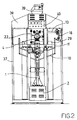
- 1 denotes the fixed vertical column located above a base 2.
- a horizontal arm 3, at a right angle to the fixed vertical column 1 is comprised of a portion 3a which is fixed in relation to fixed vertical column 1 and a portion 3b which is mobile in relation to the aforementioned fixed vertical column.
- a mould 4 is positioned on the fixed portion 3a.
- the said mould is movable along the longitudinal axis of the horizontal arm 3 and can be held in place using a control operated by a clamping element 5.
- extractors 6 On the corners of the front side of the mould 4 are some extractors 6 which move vertically, are driven pneumatically and are synchronised with the machine's functioning cycle.
- the said extractors have a groove into which a cord 7 can be placed which will then create laces 8 as a result of the action of the aforementioned mould.
- a length adjuster 9 for the cord 7, and therefore for the laces 8, has a pantograph device 10 which extends widthways.
- the said adjuster 9 is attached to the fixed vertical column 1 in such a way as to allow it to slide along the aid fixed vertical column and it has ends to which vertical rods 11 are attached.
- the said vertical rods can be moved both closer to and farther from the fixed vertical column 1 at the same time, along a surface positioned at a right angle to the longitudinal axis of the horizontal arm 3.
- a specially-designed clamping means 12 allows the adjuster 9 to be fixed at the height required.
- an arm 13 hinged to a shaft (not shown) and rotating inside the vertical column 1 with continuous motion, the aforementioned rotation being driven by a gear motor 14.
- a rotating head 16 At one end of the arm 13, there is a rotating head 16, to which is attached a cord guide 17 shaped like a cylindrical cable.
- the cord guide 17 has an acetone spray nozzle 18 attached to it, which is supplied with acetone by a specially-designed duct (not shown), from a tank 19 positioned inside the base 2.
- the inside of the cord guide 17 is connected to the spray nozzle 18 by a hole 20.
- a linear cam 22 In the upper part of the mould 4 is a linear cam 22, whose height and inclination can be adjusted and whose upper profile is designed to be travelled over by a feeler point element 23 of a squirt 24 attached integrally to the rotating head 16.
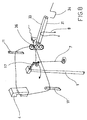
- a storage station 25 for the laces 8 is attached integrally to a mobile platform 26, along which it is moved by means of longitudinal guides 27.
- the aforementioned storage station 25 is composed of a feeder 28 and a collection device 29.
- Both the feeder 28 and the collection device 29 are attached integrally to the mobile platform 26.
- the upper part of the feeder 28 has a sloping surface 30 in position with which there is a first plurality of belts 31, the upper part of which follows the profile of the sloping surface 30.
- the collection device 29 has an protruding portion 32 located over the sloping surface 30, whose inclination it copies. Inside this protruding portion 32 is a second plurality of motorised belts 33.
- the two pluralities of belts 31 and 33 are in mutual contact.
- the collection device 29 is fitted with a plurality of hooks 34, all of which are attached to a commonly-known and autonomous motorised rotating device 35.
- a peripheral casing 37 contains everything just described, the said casing being fitted with transparent, accident prevention surfaces.
- the peripheral casing 37 is sealed at the top, completely, by a cover 38, shaped like a hood.
- a support 41 inside the peripheral casing, supports a spindle 42 holding a strip of the material to be used to tip the laces 8.
- the length of the laces required must be decided so that the necessary adjustments can be made to the various mechanical parts.
- the height of the adjuster 9 is adjusted with the relative clamping means 12 and the opening of the pantograph device 10, which extends widthways, is adjusted in order to adjust the distance between the two vertical rods 11 in relation to the external surface on which the cord 7 is resting while the machine is functioning.
- a further adjustment that must be made during this preparatory phase is the setting of the data required in a control panel 42.
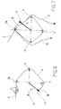
- the rotating head 16 After positioning the aforementioned cord in the mould 4, the rotating head 16 is made to move along its circular route.
- the cord 7, although cut and tipped inside the mould 4, is held by the mould itself and so the rotating head 16, in moving along its circular route, continues to unwind the cord 7, taking it to the second vertical rod 11.
- portion B After portion B has been held by the pinching device 38, the mould 4 opens so both portions A and B of the cord 7 held therein are released.
- Portion A is taken in by the two pluralities of belts 31 and 33 and transported by these latter to a hook 34 on the collection device 29.
- Portion A must now be considered waste because it has only one tipped end.
- the machine can be started running at the speed required since portion B of the cord 7 is held by the pinching device 38 and the cord guide 17 can wind the cord itself while the rotating head 16 rotates continuously.
- portion B will have to be caught by the two pluralities of belts 31 and 33 and the uncoiling operations of the cord 7, and the cutting and tipping of the said cord 7, the storage of the laces 8 created in this way will take place as described earlier with the only difference being that the speed of the rotation of the rotating head 16 will be the production speed.
- acetone may well be dragged out of the cord guide 17 because of the wet cord 7 brushing against the internal surface of the cord guide itself.
- This part of the acetone runs into the container 21, where it is collected and from which it is removed by suction from the specially-designed tank 19.
- This suction is carried out by means of a Venturi meter (not shown) in order to obtain the necessary head for the suction required using a simple and cheap means.
- the rotating head 16 After the rotating head 16 has passed over the mould 4, this latter is activated by a control driven by another of the eccentricities 15.
- the action of the aforementioned mould 4 is commonly known and consists in the cutting of the cord 7 in position with the section of cord 7 sprayed with acetone earlier and in the wrapping of the two ends created in this way with a suitable material (either plastic or celluloid in the case of the machine in question in the present invention), which comes from a spindle 42.
- the acetone vapours released during the working process are removed from the workplace by means of the suction device 39.
- the shoelaces 8 are then taken up by the two pluralities of belts 31 and 33.
- the individual laces 8 are caught by the mutual contact between the aforementioned two pluralities of belts and these latter then force them along the route towards the bottom of the sloping surface 30.
- the individual shoelaces 8 fall, because of the force of gravity, onto one of the hooks 34 of the collection device 29 (a commonly-known type) and remain hung there.
- a first advantage of the procedure in question in the present invention is that the machine offers the possibility to save a considerable amount of space because of its substantially circular build.
- a further advantage of the present invention is that the machine needs very little maintenance, which has a positive effect on the management costs.
Landscapes
- Braiding, Manufacturing Of Bobbin-Net Or Lace, And Manufacturing Of Nets By Knotting (AREA)
- Harvester Elements (AREA)
- Preliminary Treatment Of Fibers (AREA)
Applications Claiming Priority (2)
| Application Number | Priority Date | Filing Date | Title |
|---|---|---|---|
| IT1999MO000118A IT1310603B1 (it) | 1999-05-27 | 1999-05-27 | Macchina per tagliare e puntalare automaticamente stringhe dotata difunzionamento rotante continuo |
| ITMO990118 | 1999-05-27 |
Publications (2)
| Publication Number | Publication Date |
|---|---|
| EP1055378A2 true EP1055378A2 (de) | 2000-11-29 |
| EP1055378A3 EP1055378A3 (de) | 2002-07-31 |
Family
ID=11386986
Family Applications (1)
| Application Number | Title | Priority Date | Filing Date |
|---|---|---|---|
| EP00110880A Withdrawn EP1055378A3 (de) | 1999-05-27 | 2000-05-23 | Maschine mit kontinuierlicher Drehfunktion zum automatisch Schneiden von Schnürsenkeln und Behandeln von Senkelenden |
Country Status (2)
| Country | Link |
|---|---|
| EP (1) | EP1055378A3 (de) |
| IT (1) | IT1310603B1 (de) |
Cited By (6)
| Publication number | Priority date | Publication date | Assignee | Title |
|---|---|---|---|---|
| CN106510102A (zh) * | 2016-12-30 | 2017-03-22 | 东莞市鸿程机械有限公司 | 一种绳带自动包胶装置 |
| CN112137250A (zh) * | 2020-10-08 | 2020-12-29 | 东莞市瑞硕鞋材有限公司 | 一种弹力鞋带裁切控制设备 |
| CN112191764A (zh) * | 2020-10-21 | 2021-01-08 | 东莞百宏实业有限公司 | 自动打束头机 |
| US11548053B1 (en) * | 2021-01-08 | 2023-01-10 | Adam Maga | Device to install shoelace aglets |
| CN115868715A (zh) * | 2021-09-28 | 2023-03-31 | 裕发科技股份有限公司 | 自动化穿鞋扣机 |
| CN117158694A (zh) * | 2023-09-06 | 2023-12-05 | 瑞安市远久鞋业有限公司 | 一种用于休闲鞋鞋带生产的切断装置 |
Family Cites Families (4)
| Publication number | Priority date | Publication date | Assignee | Title |
|---|---|---|---|---|
| DE367407C (de) * | 1922-04-25 | 1923-01-20 | Gustav Mueller & Co | Einrichtung zum Pressen von Zelluloidnadeln an Schnuerriemen |
| DE501926C (de) * | 1926-12-07 | 1930-07-07 | Wilhelm Moeschet | Maschine zur Herstellung von Schnuerriemen mit umflochtenen Celluloidnadeln |
| GB514220A (en) * | 1938-04-30 | 1939-11-02 | Andor Ney | Improvements in or relating to the manufacture of threading-tips for boot and shoe laces |
| US2740156A (en) * | 1951-01-23 | 1956-04-03 | Spach Andre Albert | Machine for tagging laces |
-
1999
- 1999-05-27 IT IT1999MO000118A patent/IT1310603B1/it active
-
2000
- 2000-05-23 EP EP00110880A patent/EP1055378A3/de not_active Withdrawn
Non-Patent Citations (1)
| Title |
|---|
| None |
Cited By (6)
| Publication number | Priority date | Publication date | Assignee | Title |
|---|---|---|---|---|
| CN106510102A (zh) * | 2016-12-30 | 2017-03-22 | 东莞市鸿程机械有限公司 | 一种绳带自动包胶装置 |
| CN112137250A (zh) * | 2020-10-08 | 2020-12-29 | 东莞市瑞硕鞋材有限公司 | 一种弹力鞋带裁切控制设备 |
| CN112191764A (zh) * | 2020-10-21 | 2021-01-08 | 东莞百宏实业有限公司 | 自动打束头机 |
| US11548053B1 (en) * | 2021-01-08 | 2023-01-10 | Adam Maga | Device to install shoelace aglets |
| CN115868715A (zh) * | 2021-09-28 | 2023-03-31 | 裕发科技股份有限公司 | 自动化穿鞋扣机 |
| CN117158694A (zh) * | 2023-09-06 | 2023-12-05 | 瑞安市远久鞋业有限公司 | 一种用于休闲鞋鞋带生产的切断装置 |
Also Published As
| Publication number | Publication date |
|---|---|
| EP1055378A3 (de) | 2002-07-31 |
| ITMO990118A0 (it) | 1999-05-27 |
| IT1310603B1 (it) | 2002-02-19 |
| ITMO990118A1 (it) | 2000-11-27 |
Similar Documents
| Publication | Publication Date | Title |
|---|---|---|
| CN107635899B (zh) | 用于铺展织物的机器 | |
| KR101932738B1 (ko) | 미용 마스크 팩 자동 폴딩장치 | |
| US4133280A (en) | Automatic method and apparatus for closing a toe end of a hose utilizing a straight line stitch | |
| EP1055378A2 (de) | Maschine mit kontinuierlicher Drehfunktion zum automatisch Schneiden von Schnürsenkeln und Behandeln von Senkelenden | |
| US4265187A (en) | Apparatus for applying elastic rings to tubular garments | |
| CN207632206U (zh) | 一种纺织用布料输送机 | |
| US4634065A (en) | Device for inserting the thread end of a textile bobbin into a bobbin sleeve | |
| JPS5915676B2 (ja) | ミシンにおける繊維材料製筒状部材の装填装置 | |
| JP3346418B2 (ja) | 開梱及び混合装置 | |
| US4628671A (en) | Apparatus for packing produce, such as lettuce, bunches of carrots, asparagus, bananas and the like | |
| CN107600480B (zh) | 服装生产加工传输设备 | |
| US4622713A (en) | Fly removing system in textile machine | |
| ITBO20000035A1 (it) | Unita' di gommatura . | |
| GB1491444A (en) | Machines for sealing articles in tubular packaging material | |
| BE1008415A6 (nl) | Weefmachine met kapsels. | |
| ITBO20130359A1 (it) | Un apparato per il trattamento di rispettivi prodotti, in particolare per etichettare detti prodotti. | |
| KR100919431B1 (ko) | 칫솔모 가공, 배출 및 포장 자동화시스템 | |
| EP0820944A1 (de) | Zuführeinheit für Verpackungsmaterial | |
| KR101562734B1 (ko) | 코팅장갑 제조장치 | |
| NL7600569A (nl) | Weefmachine met een pneumatisch bediende buffer- inrichting voor het inslaggaren. | |
| KR101927517B1 (ko) | 허니콤 블라인드 원단의 성형장치 | |
| US3099047A (en) | Apparatus for breaking fibrous masses | |
| US4069561A (en) | Selvedge protection apparatus for loop pile fabric cutting machine | |
| US3481106A (en) | Wrapper closing apparatus | |
| US3191473A (en) | Apparatus for cutting a leaf of predetermined shape out of a tobacco leaf |
Legal Events
| Date | Code | Title | Description |
|---|---|---|---|
| PUAI | Public reference made under article 153(3) epc to a published international application that has entered the european phase |
Free format text: ORIGINAL CODE: 0009012 |
|
| AK | Designated contracting states |
Kind code of ref document: A2 Designated state(s): AT BE CH CY DE DK ES FI FR GB GR IE IT LI LU MC NL PT SE |
|
| AX | Request for extension of the european patent |
Free format text: AL;LT;LV;MK;RO;SI |
|
| 17P | Request for examination filed |
Effective date: 20010518 |
|
| PUAL | Search report despatched |
Free format text: ORIGINAL CODE: 0009013 |
|
| AK | Designated contracting states |
Kind code of ref document: A3 Designated state(s): AT BE CH CY DE DK ES FI FR GB GR IE IT LI LU MC NL PT SE |
|
| AX | Request for extension of the european patent |
Free format text: AL;LT;LV;MK;RO;SI |
|
| RIC1 | Information provided on ipc code assigned before grant |
Free format text: 7A 43D 99/00 A, 7A 43C 9/00 B, 7A 43C 9/04 B |
|
| GRAH | Despatch of communication of intention to grant a patent |
Free format text: ORIGINAL CODE: EPIDOS IGRA |
|
| AKX | Designation fees paid |
Designated state(s): AT BE CH CY DE DK ES FI FR GB GR IE IT LI LU MC NL PT SE |
|
| STAA | Information on the status of an ep patent application or granted ep patent |
Free format text: STATUS: THE APPLICATION IS DEEMED TO BE WITHDRAWN |
|
| 18D | Application deemed to be withdrawn |
Effective date: 20030815 |