EP1053915A1 - Générateur hybride à pilier perforateur - Google Patents
Générateur hybride à pilier perforateur Download PDFInfo
- Publication number
- EP1053915A1 EP1053915A1 EP00401274A EP00401274A EP1053915A1 EP 1053915 A1 EP1053915 A1 EP 1053915A1 EP 00401274 A EP00401274 A EP 00401274A EP 00401274 A EP00401274 A EP 00401274A EP 1053915 A1 EP1053915 A1 EP 1053915A1
- Authority
- EP
- European Patent Office
- Prior art keywords
- cylindrical
- gas
- piston
- pyrotechnic
- column
- Prior art date
- Legal status (The legal status is an assumption and is not a legal conclusion. Google has not performed a legal analysis and makes no representation as to the accuracy of the status listed.)
- Granted
Links
Images


Classifications
-
- B—PERFORMING OPERATIONS; TRANSPORTING
- B60—VEHICLES IN GENERAL
- B60R—VEHICLES, VEHICLE FITTINGS, OR VEHICLE PARTS, NOT OTHERWISE PROVIDED FOR
- B60R21/00—Arrangements or fittings on vehicles for protecting or preventing injuries to occupants or pedestrians in case of accidents or other traffic risks
- B60R21/02—Occupant safety arrangements or fittings, e.g. crash pads
- B60R21/16—Inflatable occupant restraints or confinements designed to inflate upon impact or impending impact, e.g. air bags
- B60R21/26—Inflatable occupant restraints or confinements designed to inflate upon impact or impending impact, e.g. air bags characterised by the inflation fluid source or means to control inflation fluid flow
- B60R21/268—Inflatable occupant restraints or confinements designed to inflate upon impact or impending impact, e.g. air bags characterised by the inflation fluid source or means to control inflation fluid flow using instantaneous release of stored pressurised gas
- B60R21/272—Inflatable occupant restraints or confinements designed to inflate upon impact or impending impact, e.g. air bags characterised by the inflation fluid source or means to control inflation fluid flow using instantaneous release of stored pressurised gas with means for increasing the pressure of the gas just before or during liberation, e.g. hybrid inflators
-
- F—MECHANICAL ENGINEERING; LIGHTING; HEATING; WEAPONS; BLASTING
- F42—AMMUNITION; BLASTING
- F42B—EXPLOSIVE CHARGES, e.g. FOR BLASTING, FIREWORKS, AMMUNITION
- F42B3/00—Blasting cartridges, i.e. case and explosive
- F42B3/04—Blasting cartridges, i.e. case and explosive for producing gas under pressure
- F42B3/045—Hybrid systems with previously pressurised gas using blasting to increase the pressure, e.g. causing the gas to be released from its sealed container
Definitions
- the present invention relates to the field of protection of the occupants of a motor vehicle using an airbag. More precisely the invention relates to a hybrid gas generator, tubular shape, allowing to inflate such a cushion.
- a pyrotechnic primer placed at the back of the piston causes the advancement of the piston which tears off the cover and allows cold gases under pressure to enter said pipeline.
- the hot gases from the combustion of the pyrotechnic charge cannot mix with gases cold, these are heated by passing over a magnesium bed which reacts with them.
- Such a device is dangerous in principle and requires complex realization.
- PCT application WO 98/09850 thus describes a tubular hybrid generator containing a gas under pressure as well as a piston coupled to an initiator pyrotechnic.
- the ignition of the initiator causes the displacement of the piston which opens the generator at its end opposite to the initiator pyrotechnics and also the warming of gases cold by mixing, inside the generator, these last with hot gases supplied by the initiator pyrotechnic.
- the amount of gas storable in the generator is limited well in below its maximum theoretical value.
- the realization of a generator in which the stroke of the piston must be guided along the entire length of the generator is relatively expensive.
- Tubular hybrid generators are particularly sought after to ensure the inflation of protective cushions, front or side, intended to motor vehicle passengers but the man of profession does not currently have tubular hybrid generators which are both simple to carry out and which fully ensure mixture of hot gases from the combustion of pyrotechnic charge with stored cold gases in the tank, outside the latter.
- the object of the present invention is precisely to propose such a generator.
- a full movable piston presenting in its downstream part a column which can penetrate into the central opening of the internal partition without closing it and in its rear part an enlarged solid base and extended by ribs peripheral to the column of so as to prevent the said central opening from being blocked by the said base, which makes it possible to achieve the object of the invention.
- the gases can leave the tank chamber through the part of the central opening of the internal partition left free by the piston column to penetrate in the combustion and mixing chamber.
- the enlarged base of the piston serves as a deflector hot gases from the combustion of the load pyrotechnic. These hot gases cannot penetrate in the reservoir chamber but are led to mix with cold gases to form the mixture gas leaving the generator through its orifices exit.
- said support piece is constituted by a hollow ring crimped against the body of the generator, said ring having a central cylindrical recess having an internal shoulder so as to have a diameter d 1 opposite the pyrotechnic charge and a diameter d 2 opposite the internal partition, d 2 being greater than d 1 , the said ring being extended opposite the internal partition by a hollow cylindrical neck whose internal diameter is equal to d 2 and whose outer diameter is less than the inner diameter of the tubular body.
- the said full movable piston advantageously consists on the one hand of a cylindrical body having a cylindrical tail with an outside diameter d 1 , a cylindrical base with an outside diameter d 3 between d 1 and d 2 and a cylindrical column of cross section s and of length l, and on the other hand by fins, of height h less than l, which surround the column and which rest on the base of said body, said fins constituting the peripheral ribs.
- the base of the movable piston rests on the internal shoulder presented by the support ring and the tail of the piston, the height of which should be less than the piston stroke, enters the central recess of the ring which is opposite of the pyrotechnic charge.
- hot gases start with push the movable piston without being able to mix with cold gases from the reservoir chamber.
- the said fins constitute a part single with a central channel of section s, the so-called part being force fitted on said column of the piston.
- the cylindrical body of the piston will a metallic body and the so-called single piece will constituted by a rigid plastic material.
- tubular body of the generator will consisting of a single metal tube.
- internal partition and its cover will advantageously fixed to said metal tube by a single operation of laser welding performed from the outside by transparency through this tube.
- the invention thus makes it possible to have a simple and inexpensive hybrid tubular generator to to assemble.
- This generator makes it possible to mix gases hot and cold gases while preventing the gases hot gases enter the cold gas supply. In given volume of the tank chamber so it's possible to compress more gas important than that which can be stored in a hybrid generator with the same characteristics but does not not presenting this security.
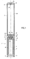
- FIG. 1 shows a hybrid generator gas 1 according to the invention.
- This generator 1 is constituted by a tubular body 2 made of steel.
- Tube 2 has an upstream end 3 in which is crimped a metal ring 5 forming part of a device pyrotechnic ignition 4 not cut but shown in detail in Figures 7 and 8.
- the priming device 4 thus consists of a igniter holder 6 having a ring-shaped base 5 hollow which is extended by a hollow neck 7 in which is crimped an electropyrotechnic igniter 8 whose electrodes 9 are protected by a ring-shunt 10.
- a cylindrical metal cap 11 encloses the neck 7 and comes to rest on base 5 thanks to a part flared 12 glued to said base 5. At its end opposite said flared part 12, the cap 11 has a flat face 13 precut and which can open due to increased pressure.
- the igniter 8 has a narrow upper part 14 surrounded by a spring 15 which supports a load pyrotechnic 16 in the form of a multi-perforated lobed block.
- the pyrotechnic charge 16 will advantageously consisting of a block of composite propellant based on ammonium perchlorate and sodium nitrate and containing a silicone binder as described for example in US patent 5,610,444, the cap 11 ensuring, before operation, gas-tight insulation.
- a spacer tubular plastic 20 is interposed between the cap 11 and the tube 2 to act as volume compensator and avoid lateral bursting of the cap 11 when the load is switched on 16.
- the tube 2 also has a downstream end 21 onto which a metal plug 22 is welded having a filling port 23 for gases.
- This orifice 23 is itself closed in leaktight manner by a solder plug 24.
- the tube 2 Downstream of the pyrotechnic ignition device 4, the tube 2 has gas outlet orifices 25 whose centers are distributed in the same radial plane perpendicular to the generatrices of the cylindrical tube 2.
- the tube 2 Downstream of these orifices 25 the tube 2 contains a internal partition 26 which has the shape of a flat disc having a central orifice 27 of circular section S.
- the partition 26 is arranged inside a cap-cap 28.
- the partition 26 and the cap-cap 28 consist of metallic elements and can thus be fixed in a gas-tight manner to tube 2 by a single laser welding operation.
- inert gases such as nitrogen, argon, helium or mixtures of gases inert and oxidizing gases such as air or mixtures argon / oxygen.
- gases inert and oxidizing gases such as air or mixtures argon / oxygen.
- the tubular body 2 also contains in its upstream part a hollow support piece 30 which comes to the contact of the face 13 of the cap 11 of the device priming 4.
- This hollow support piece 30 is fixed to the tube 2 by crimping without coming into contact with the internal partition 26 nor of the gas outlet orifices 25.
- the support piece 30 contains a movable piston 31 full having a column 32 of section smaller than the section S of the central orifice 27 carried by the partition internal 26. This column 32 bears against the cover 28 closing the orifice 27 and thus constitutes a pillar which strengthens the resistance of said seal to the pressure of the gases contained in the chamber 29.
- the support piece 30 is a metal piece constituted by a hollow cylindrical ring 33 which comes into contact with the spacer 20 and which is fixed by crimping in the tube 2, the flat downstream surface 34 of this ring 33 coming to the upstream limit orifices 25 without obstructing them.
- the ring 33 has a central cylindrical recess 35 having an internal shoulder 36.
- the recess 35 has a diameter d 1 opposite the pyrotechnic charge 16 and a distinct diameter d 2 opposite the internal partition 26, d 2 being greater than both at d 1 and at the diameter d of the central orifice 27 of the partition 26.
- the hollow ring 33 is extended opposite the internal partition 26 by a hollow cylindrical neck 37 which does not come into contact with said partition 26 The inside diameter of this neck 37 is equal to d 2 while its outside diameter is less than the inside diameter of the tubular body 2.
- the piston 31 is firstly constituted by a cylindrical metallic body 38 having a cylindrical tail 39 of external diameter d 1 and having a central reinforcement 40 whose role will be explained later in the description.
- the body 38 also has a solid cylindrical base 41 with an outside diameter d 3 of between d 1 and d 2 .
- the body 38 has a cylindrical column 32 of section s and of length 1.
- the body 38 consists of a single metal part, the column 32 being obtained by the discharge of the metal initially occupying the volume of the reinforcement 40.
- the piston 31 is on the other hand constituted by a single piece 42 of rigid plastic material uniform h and having a central cylindrical channel 43 of section s allowing said part 42 to be force-fitted onto column 32 of body 38 to constitute the piston 31.
- the single piece 42 has 3 lateral sectors in the form of fins 44.
- the height h of the single piece 42 and therefore of the fins 44 is less than the length l of column 32 and even, in the illustrated embodiment, less than the height of the neck 37 of the support piece 30.
- the maximum diametrical size of the single piece 42 is also equal to d 2 .
- the part 42 rests on the base 41 of the body 38 and the fins 44 surround column 32, thus constituting, with respect to this column, external ribs 45.
- the tail 39 of the body 38 enters the upstream part of the recess 35. This making the hollow support piece 30 and the piston 31 separate in a gas-tight manner, the orifices 25 of gas outlet and pyrotechnic charge 16 content in the priming device 4.
- the assembly of generator 1 which has just been described is very simple to carry out.
- the partition 26 as well as the cap lid 28 are then fixed to tube 2 by a single laser welding operation performed from the outside by transparency through tube 2.
- the stopper metal 22 is then welded to the downstream end 21 of the tube 2.
- the support piece 30 containing the piston 31 is then placed and crimped in the tube 2 so the end of column 32 comes into contact of the cover cap 28.
- the spacer 20 and the pyrotechnic ignition device 4 are then put in place and we proceed to crimp the tube 2 on the ring 5 of the priming device 4.
- the reservoir chamber 29 is finally filled with gas through port 23 which is then closed by the solder plug 24.
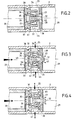
- the piston 31 Under the thrust of the load's combustion gases pyrotechnic 16, the piston 31 continues to advance but its course is stopped when the ribs external 45 abuts against the internal partition 26 thus preventing the base 41 of the piston 31 from blocking the central orifice 27 of the internal partition 26. At this moment the tail 39 of the piston 31 whose length must be less than the piston stroke is no longer engaged in the narrow part of the recess 35 and the gases hot from the combustion of the load pyrotechnics 16 can enter the mixing by bypassing the base 41 of the piston 31 to mix with cold gases from the chamber tank 29 and leave the generator through the openings 25.
- the solid base 41 of the piston 31 constitutes a deflector preventing gases hot to go directly to the central hole 27 of the internal partition 26 which prevents them in convenient to enter the tank chamber 29.
- room 29 used in a generator according to the invention can therefore contain more than gas as the same chamber used in a generator traditional hybrid does not prevent entry of gases hot in the tank chamber.
Landscapes
- Engineering & Computer Science (AREA)
- Physics & Mathematics (AREA)
- Fluid Mechanics (AREA)
- Mechanical Engineering (AREA)
- General Engineering & Computer Science (AREA)
- Air Bags (AREA)
- Feeding, Discharge, Calcimining, Fusing, And Gas-Generation Devices (AREA)
- Suspension Of Electric Lines Or Cables (AREA)
- Earth Drilling (AREA)
- Road Signs Or Road Markings (AREA)
- Catching Or Destruction (AREA)
Abstract
Description
- une partie amont formant une chambre de combustion et de mélange contenant le dispositif d'amorçage, les orifices de sortie des gaz ainsi qu'un chargement pyrotechnique générateur de gaz chauds,
- une partie aval formant une chambre réservoir
contenant au moins un gaz sous pression,
caractérisé en ce que le dit corps tubulaire contient dans sa partie amont, entre le chargement pyrotechnique et la dite cloison interne, une pièce-support qui est fixée au dit corps tubulaire sans venir au contact de la dite cloison interne ni des dits orifices de sortie des gaz et qui contient un piston mobile plein constitué par au moins une colonne de section s inférieure à la section S qui vient en appui contre l'opercule fermant l'orifice central de la cloison interne, la dite colonne présentant à son extrémité opposée à la dite cloison une base pleine de section So supérieure à S qui porte des nervures périphériques empêchant la dite base de venir au contact du dit orifice central. En général la pièce-support sera creuse et les nervures périphériques seront situées en dehors du dit orifice central.
- une partie amont contenant le dispositif d'amorçage 4 avec son chargement pyrotechnique 16 ainsi que les orifices 25 de sortie des gaz, cette partie amont formant une chambre de combustion et de mélange 46,
- une partie aval formant une chambre réservoir 29 destinée à contenir au moins un gaz sous pression.
Claims (7)
- Générateur hybride (1) de gaz constitué par un corps tubulaire (2) présentant une extrémité amont (3) fermée par un dispositif d'amorçage pyrotechnique (4) et une extrémité aval (21) fermée de manière étanche aux gaz, le dit corps tubulaire présentant également des orifices (25) de sortie des gaz et contenant une cloison interne (26) présentant un orifice central (27) de section S fermé par un opercule (28), la dite cloison divisant le dit corps tubulaire en deux parties :caractérisé en ce que le dit corps tubulaire est constitué par un tube métallique unique et contient dans sa partie amont, entre le chargement pyrotechnique et la dite cloison interne (26) une pièce-support (30) qui est fixée audit corps sans venir au contact de la dite cloison interne ni des dits orifices de sortie des gaz et qui contient un piston mobile plein (31) constitué par au moins une colonne (32) de section s, inférieure à la section S, qui vient en appui contre l'opercule (28) fermant l'orifice central (27) de la cloison interne (26), la dite colonne (32) présentant, à son extrémité opposée à la dite cloison une base pleine (41) de section So supérieure à S qui porte des nervures périphériques (45) empêchant la dite base (41) de venir au contact du dit orifice central (27).une partie amont formant une chambre de combustion et de mélange (46) et contenant le dispositif d'amorçage, les orifices de sortie des gaz ainsi qu'un chargement pyrotechnique (16) générateur de gaz chauds,une partie aval formant une chambre réservoir (29) contenant au moins un gaz sous pression,
- Générateur hybride selon la revendication 1 caractérisé en ce que, avant fonctionnement pyrotechnique, la dite pièce-support (30) et le dit piston mobile plein (31) isolent le dit chargement pyrotechnique (16) des dits orifices (25) de sortie de gaz.
- Générateur hybride selon la revendication 2 caractérisé en ce que la dite pièce-support (30) est constituée par une bague creuse (33) sertie contre le corps (2) du générateur (1), la dite bague présentant un évidement cylindrique central (35) possédant un épaulement interne (36) de manière à avoir un diamètre d1 en regard du chargement pyrotechnique (16) et un diamètre d2 en regard de la cloison interne (26), d2 étant supérieur à d1, la dite bague (33) étant prolongée en regard de la cloison interne (26) par un col cylindrique creux (37) dont le diamètre intérieur est égal à d2 et dont le diamètre externe est inférieur au diamètre intérieur du corps tubulaire (2).
- Générateur hybride selon la revendication 3 caractérisé en ce que le dit piston mobile (31) est constitué d'une part par un corps cylindrique (38) présentant une queue cylindrique (39) de diamètre extérieur d1, une base cylindrique (41) de diamètre extérieur d3 compris entre d1 et d2 et une colonne cylindrique (32) de section s et de longueur l, et d'autre part par des ailettes (44) de hauteur h inférieure à la longueur l qui entourent la colonne (32) et qui reposent sur la base (41) du dit corps, les dites ailettes constituant les nervures périphériques (45).
- Générateur hybride selon la revendication 4 caractérisé en ce que les dites ailettes (44) constituent une pièce unique (42) présentant un canal central cylindrique de section s, la dite pièce étant emmanchée en force sur la dite colonne (32) du corps cylindrique (38).
- Générateur hybride selon la revendication 5 caractérisé en ce que le dit corps cylindrique (38) est un corps métallique et en ce que la dite pièce (42) est constituée par une matière plastique rigide.
- Générateur hybride selon la revendication 7 caractérisé en ce que la cloison interne (26) et l'opercule (28) sont fixés au corps tubulaire (2) par une seule opération de soudure laser effectuée depuis l'extérieur par transparence à travers le dit corps tubulaire (2).
Applications Claiming Priority (2)
| Application Number | Priority Date | Filing Date | Title |
|---|---|---|---|
| FR9906468 | 1999-05-21 | ||
| FR9906468A FR2793748B1 (fr) | 1999-05-21 | 1999-05-21 | Generateur hybride a pilier perforateur |
Publications (2)
| Publication Number | Publication Date |
|---|---|
| EP1053915A1 true EP1053915A1 (fr) | 2000-11-22 |
| EP1053915B1 EP1053915B1 (fr) | 2003-08-06 |
Family
ID=9545857
Family Applications (1)
| Application Number | Title | Priority Date | Filing Date |
|---|---|---|---|
| EP00401274A Expired - Lifetime EP1053915B1 (fr) | 1999-05-21 | 2000-05-10 | Générateur hybride à pilier perforateur |
Country Status (9)
| Country | Link |
|---|---|
| US (1) | US6231079B1 (fr) |
| EP (1) | EP1053915B1 (fr) |
| JP (1) | JP3474830B2 (fr) |
| KR (1) | KR100351224B1 (fr) |
| AT (1) | ATE246615T1 (fr) |
| CA (1) | CA2308894C (fr) |
| DE (1) | DE60004289T2 (fr) |
| ES (1) | ES2204465T3 (fr) |
| FR (1) | FR2793748B1 (fr) |
Cited By (2)
| Publication number | Priority date | Publication date | Assignee | Title |
|---|---|---|---|---|
| EP1160138A1 (fr) * | 2000-05-30 | 2001-12-05 | Livbag S.N.C. | Générateur hybride à pilier perforateur et à corps bi-tubulaire |
| EP1322505A4 (fr) * | 2000-08-03 | 2005-10-05 | Nxgen Technologies Llc | Gonfleur pour appareil de protection de vehicule |
Families Citing this family (23)
| Publication number | Priority date | Publication date | Assignee | Title |
|---|---|---|---|---|
| DE19933556A1 (de) * | 1999-07-16 | 2001-01-18 | Autoliv Dev | Aufblasvorrichtung für Kraftfahrzeug-Sicherheitseinrichtungen |
| DE20107130U1 (de) | 2001-04-25 | 2001-06-21 | TRW Airbag Systems GmbH & Co. KG, 84544 Aschau | Gassackmodul |
| JP4612232B2 (ja) * | 2001-06-20 | 2011-01-12 | 日本化薬株式会社 | ガス発生器 |
| JP4708606B2 (ja) * | 2001-06-29 | 2011-06-22 | ダイセル化学工業株式会社 | ハイブリッドインフレータ |
| US20030057689A1 (en) * | 2001-06-29 | 2003-03-27 | Nobuyuki Katsuda | Hybrid inflator |
| US6851709B2 (en) | 2001-08-31 | 2005-02-08 | Daicel Chemical Industries, Ltd. | Multistage-inflating type hybrid inflator |
| JP4864250B2 (ja) * | 2001-08-31 | 2012-02-01 | 株式会社ダイセル | 多段膨張式ハイブリッドインフレータ |
| FR2831122B1 (fr) * | 2001-10-19 | 2004-07-30 | Livbag Snc | Dispositif generateur de gaz hybride pour gonfler un coussin de protection utilise en securite automobile |
| FR2831123B1 (fr) * | 2001-10-19 | 2004-07-30 | Livbag Snc | Dispositif generateur de gaz hybride utilise en securite automobile pour gonfler un coussin de protection lateral |
| TW595560U (en) * | 2003-05-05 | 2004-06-21 | Chung Shan Inst Of Science | Combinative inflation device |
| DE20318283U1 (de) * | 2003-11-26 | 2004-04-01 | Trw Airbag Systems Gmbh | Gasgenerator |
| US7588265B2 (en) * | 2004-04-12 | 2009-09-15 | Automotive Systems Laboratory, Inc. | Pressurized gas release mechanism |
| US7695009B2 (en) * | 2005-01-13 | 2010-04-13 | Autoliv Development Ab | Inflator for an air-bag |
| US7641230B2 (en) * | 2005-06-15 | 2010-01-05 | Autoliv Asp, Inc. | Extended fill inflation apparatus |
| FR2939742B1 (fr) * | 2008-12-15 | 2011-12-23 | Livbag | Generateur de gaz hybride, pour le gonflage d'un coussin de protection gonflable pour vehicule automobile |
| DE102012011988A1 (de) * | 2012-06-16 | 2013-12-19 | Atlas Elektronik Gmbh | Verschlussvorrichtung für einen Druckspeicher, Torpedo mit einem Druckspeicher und einer solchen Verschlussvorrichtung für den Druckspeicher sowie Verwendung einer solchen Verschlussvorrichtung für den Verschluss eines Druckspeichers eines Torpedos |
| JP5985960B2 (ja) * | 2012-11-08 | 2016-09-06 | 株式会社ダイセル | ガス発生器 |
| FR3010362B1 (fr) * | 2013-09-09 | 2015-10-02 | Livbag Sas | Generateur de gaz |
| JP6219136B2 (ja) * | 2013-11-13 | 2017-10-25 | 株式会社ダイセル | ガス発生器 |
| JP6251662B2 (ja) * | 2014-09-29 | 2017-12-20 | 株式会社ダイセル | ガス発生器 |
| JP6312571B2 (ja) * | 2014-09-29 | 2018-04-18 | 株式会社ダイセル | ガス発生器 |
| DE102014018007B4 (de) | 2014-12-05 | 2025-10-30 | Zf Airbag Germany Gmbh | Hybridgasgenerator für ein Fahrzeugsicherheitssystem mit einer Öffnungsvorrichtung für einen Druckgasbehälter |
| DE202016001333U1 (de) | 2016-02-12 | 2017-05-17 | Trw Airbag Systems Gmbh | Hybridgasgenerator, Gassackmodul und Fahrzeugsicherheitssystem |
Citations (8)
| Publication number | Priority date | Publication date | Assignee | Title |
|---|---|---|---|---|
| US3690695A (en) | 1970-08-14 | 1972-09-12 | Jones Sr John L | Personnel restraint system for vehicular occupants |
| US5464247A (en) | 1994-09-28 | 1995-11-07 | Trw Vehicle Safety Systems Inc. | Apparatus for use in inflating an air bag and method of assembly |
| US5610444A (en) | 1994-12-22 | 1997-03-11 | Societe Nationale Des Poudres Et Explosifs | Process for continuous manufacture of pyrotechnic charges containing a silicone binder and compositions capable of being used by this process |
| DE19545077A1 (de) * | 1995-12-02 | 1997-06-05 | Mst Automotive Gmbh | Vorrichtung zum Aufblasen eines Airbags (II) |
| WO1998009850A1 (fr) | 1996-09-03 | 1998-03-12 | Dynamit Nobel Gmbh Explosivstoff- Und Systemtechnik | Generateur de gaz hybride |
| WO1998012078A1 (fr) | 1996-09-21 | 1998-03-26 | Dynamit Nobel Gmbh Explosivstoff- Und Systemtechnik | Generateur de gaz hybride pour un airbag avec un systeme d'ouverture mecanique pour la chambre d'accumulation |
| GB2322436A (en) * | 1997-02-21 | 1998-08-26 | Breed Automotive Tech | Hybrid inflator for an airbag |
| JPH10250525A (ja) * | 1997-03-07 | 1998-09-22 | Matsushita Electric Ind Co Ltd | 安全システムまたは保護システムのためのガス発生装置 |
Family Cites Families (6)
| Publication number | Priority date | Publication date | Assignee | Title |
|---|---|---|---|---|
| US5590906A (en) * | 1993-10-13 | 1997-01-07 | Trw Vehicle Safety Systems Inc. | Vehicle occupant restraint inflator |
| US5564740A (en) * | 1995-03-09 | 1996-10-15 | Trw Inc. | Air bag inflator |
| US5620204A (en) * | 1996-01-05 | 1997-04-15 | Trw Vehicle Safety Systems Inc. | Apparatus for inflating an inflatable vehicle occupant protection device |
| KR100202565B1 (ko) | 1996-03-23 | 1999-06-15 | 구자홍 | 복합영상신호의 3차원 휘도/색신호 분리 장치 |
| US5863067A (en) * | 1996-12-05 | 1999-01-26 | Trw Vehicle Safety Systems Inc. | Vehicle occupant protection apparatus |
| US6024379A (en) * | 1997-05-01 | 2000-02-15 | Trw Vehicle Safety Systems Inc. | Vehicle occupant protection apparatus |
-
1999
- 1999-05-21 FR FR9906468A patent/FR2793748B1/fr not_active Expired - Fee Related
-
2000
- 2000-05-09 US US09/567,229 patent/US6231079B1/en not_active Expired - Fee Related
- 2000-05-10 DE DE60004289T patent/DE60004289T2/de not_active Expired - Fee Related
- 2000-05-10 EP EP00401274A patent/EP1053915B1/fr not_active Expired - Lifetime
- 2000-05-10 AT AT00401274T patent/ATE246615T1/de not_active IP Right Cessation
- 2000-05-10 ES ES00401274T patent/ES2204465T3/es not_active Expired - Lifetime
- 2000-05-11 CA CA002308894A patent/CA2308894C/fr not_active Expired - Fee Related
- 2000-05-19 KR KR1020000026950A patent/KR100351224B1/ko not_active Expired - Fee Related
- 2000-05-19 JP JP2000152733A patent/JP3474830B2/ja not_active Expired - Fee Related
Patent Citations (8)
| Publication number | Priority date | Publication date | Assignee | Title |
|---|---|---|---|---|
| US3690695A (en) | 1970-08-14 | 1972-09-12 | Jones Sr John L | Personnel restraint system for vehicular occupants |
| US5464247A (en) | 1994-09-28 | 1995-11-07 | Trw Vehicle Safety Systems Inc. | Apparatus for use in inflating an air bag and method of assembly |
| US5610444A (en) | 1994-12-22 | 1997-03-11 | Societe Nationale Des Poudres Et Explosifs | Process for continuous manufacture of pyrotechnic charges containing a silicone binder and compositions capable of being used by this process |
| DE19545077A1 (de) * | 1995-12-02 | 1997-06-05 | Mst Automotive Gmbh | Vorrichtung zum Aufblasen eines Airbags (II) |
| WO1998009850A1 (fr) | 1996-09-03 | 1998-03-12 | Dynamit Nobel Gmbh Explosivstoff- Und Systemtechnik | Generateur de gaz hybride |
| WO1998012078A1 (fr) | 1996-09-21 | 1998-03-26 | Dynamit Nobel Gmbh Explosivstoff- Und Systemtechnik | Generateur de gaz hybride pour un airbag avec un systeme d'ouverture mecanique pour la chambre d'accumulation |
| GB2322436A (en) * | 1997-02-21 | 1998-08-26 | Breed Automotive Tech | Hybrid inflator for an airbag |
| JPH10250525A (ja) * | 1997-03-07 | 1998-09-22 | Matsushita Electric Ind Co Ltd | 安全システムまたは保護システムのためのガス発生装置 |
Non-Patent Citations (1)
| Title |
|---|
| PATENT ABSTRACTS OF JAPAN vol. 1998, no. 14 31 December 1998 (1998-12-31) * |
Cited By (4)
| Publication number | Priority date | Publication date | Assignee | Title |
|---|---|---|---|---|
| EP1160138A1 (fr) * | 2000-05-30 | 2001-12-05 | Livbag S.N.C. | Générateur hybride à pilier perforateur et à corps bi-tubulaire |
| FR2809693A1 (fr) * | 2000-05-30 | 2001-12-07 | Livbag Snc | Generateur hybride a pilier perforateur et a corps bi-tubulaire |
| US6460461B2 (en) | 2000-05-30 | 2002-10-08 | Livbag Snc | Hybrid generator with perforating pillar and two-tube body |
| EP1322505A4 (fr) * | 2000-08-03 | 2005-10-05 | Nxgen Technologies Llc | Gonfleur pour appareil de protection de vehicule |
Also Published As
| Publication number | Publication date |
|---|---|
| DE60004289T2 (de) | 2004-06-09 |
| ES2204465T3 (es) | 2004-05-01 |
| KR20010049375A (ko) | 2001-06-15 |
| US6231079B1 (en) | 2001-05-15 |
| JP3474830B2 (ja) | 2003-12-08 |
| EP1053915B1 (fr) | 2003-08-06 |
| JP2000354756A (ja) | 2000-12-26 |
| CA2308894C (fr) | 2004-09-21 |
| FR2793748A1 (fr) | 2000-11-24 |
| ATE246615T1 (de) | 2003-08-15 |
| KR100351224B1 (ko) | 2002-09-05 |
| CA2308894A1 (fr) | 2000-11-21 |
| FR2793748B1 (fr) | 2001-06-22 |
| DE60004289D1 (de) | 2003-09-11 |
Similar Documents
| Publication | Publication Date | Title |
|---|---|---|
| EP1053915B1 (fr) | Générateur hybride à pilier perforateur | |
| EP1160138B1 (fr) | Générateur hybride à pilier perforateur et à corps bi-tubulaire | |
| EP0864470B1 (fr) | Générateur pyrotechnique de gaz à débit et volume adaptables pour coussin de protection | |
| EP0757026B1 (fr) | Générateur pyrotechnique de gaz chauds pour coussin latéral de protection | |
| EP0849131B1 (fr) | Générateur tubulaire intégral de gaz par voie pyrotechnique, pour gonfler des coussins de protection | |
| EP1022536B1 (fr) | Générateur de gaz hybride muni d'un initiateur à chargement explosif profilé | |
| EP3479050B1 (fr) | Generateur de gaz | |
| EP1304267B1 (fr) | Générateur de gaz hybride pour un airbag | |
| EP0901946B1 (fr) | Générateur pyrotechnique adaptatif de gaz pour coussin de protection avec dispositif de neutralisation | |
| EP0849130B1 (fr) | Générateur pyrotechnique de gaz à chargement composite | |
| EP1293749B1 (fr) | Générateur de gaz hybride pour coussin gonflable de protection latérale appliqué à la sécurité automobile | |
| EP0916067B1 (fr) | Generateur hybride a injection gazeuse interne | |
| EP1304268A1 (fr) | Générateur de gaz hybride pour un airbag | |
| FR2757119A1 (fr) | Generateur pyrotechnique de gaz a combustible liquide injectable | |
| EP1551784A1 (fr) | Composition et generateur pyrotechnique, dispositif comprenant un tel generateur utilise en securite automobile | |
| FR2846699A1 (fr) | Dispositif pyrotechnique de dispersion d'un fluide liquide destine a la denaturation de valeurs, utilisant une piece a profil contondant | |
| FR2750939A1 (fr) | Generateur pyrotechnique de gaz a combustible liquide | |
| FR3139074A1 (fr) | Générateur de gaz comprenant du propergol sous pression | |
| FR2752292A1 (fr) | Generateur de gaz hybride comportant un reservoir annulaire | |
| FR2763032A1 (fr) | Generateur de gaz hybride a melangeur tubulaire pour la securite automobile | |
| FR2933929A1 (fr) | Generateur de gaz utilise en securite automobile. | |
| FR2907732A1 (fr) | Generateur de gaz hybride de gonflage d'un coussin de securite pour vehicule automobile | |
| FR2809366A1 (fr) | Dispositif de mise en oeuvre d'un element de securite | |
| FR2796936A1 (fr) | Generateur pyrotechnique de gaz a double securite d'ouverture |
Legal Events
| Date | Code | Title | Description |
|---|---|---|---|
| PUAI | Public reference made under article 153(3) epc to a published international application that has entered the european phase |
Free format text: ORIGINAL CODE: 0009012 |
|
| AK | Designated contracting states |
Kind code of ref document: A1 Designated state(s): AT BE CH CY DE DK ES FI FR GB GR IE IT LI LU MC NL PT SE |
|
| AX | Request for extension of the european patent |
Free format text: AL;LT;LV;MK;RO;SI |
|
| 17P | Request for examination filed |
Effective date: 20010522 |
|
| AKX | Designation fees paid |
Free format text: AT BE CH CY DE DK ES FI FR GB GR IE IT LI LU MC NL PT SE |
|
| GRAH | Despatch of communication of intention to grant a patent |
Free format text: ORIGINAL CODE: EPIDOS IGRA |
|
| RAP1 | Party data changed (applicant data changed or rights of an application transferred) |
Owner name: LIVBAG S.N.C. |
|
| GRAH | Despatch of communication of intention to grant a patent |
Free format text: ORIGINAL CODE: EPIDOS IGRA |
|
| GRAA | (expected) grant |
Free format text: ORIGINAL CODE: 0009210 |
|
| AK | Designated contracting states |
Designated state(s): AT BE CH CY DE DK ES FI FR GB GR IE IT LI LU MC NL PT SE |
|
| PG25 | Lapsed in a contracting state [announced via postgrant information from national office to epo] |
Ref country code: FI Free format text: LAPSE BECAUSE OF FAILURE TO SUBMIT A TRANSLATION OF THE DESCRIPTION OR TO PAY THE FEE WITHIN THE PRESCRIBED TIME-LIMIT Effective date: 20030806 Ref country code: IE Free format text: LAPSE BECAUSE OF FAILURE TO SUBMIT A TRANSLATION OF THE DESCRIPTION OR TO PAY THE FEE WITHIN THE PRESCRIBED TIME-LIMIT Effective date: 20030806 Ref country code: NL Free format text: LAPSE BECAUSE OF FAILURE TO SUBMIT A TRANSLATION OF THE DESCRIPTION OR TO PAY THE FEE WITHIN THE PRESCRIBED TIME-LIMIT Effective date: 20030806 Ref country code: CY Free format text: LAPSE BECAUSE OF FAILURE TO SUBMIT A TRANSLATION OF THE DESCRIPTION OR TO PAY THE FEE WITHIN THE PRESCRIBED TIME-LIMIT Effective date: 20030806 Ref country code: AT Free format text: LAPSE BECAUSE OF FAILURE TO SUBMIT A TRANSLATION OF THE DESCRIPTION OR TO PAY THE FEE WITHIN THE PRESCRIBED TIME-LIMIT Effective date: 20030806 |
|
| REG | Reference to a national code |
Ref country code: GB Ref legal event code: FG4D Free format text: NOT ENGLISH |
|
| REG | Reference to a national code |
Ref country code: CH Ref legal event code: EP |
|
| REG | Reference to a national code |
Ref country code: IE Ref legal event code: FG4D Free format text: FRENCH |
|
| REF | Corresponds to: |
Ref document number: 60004289 Country of ref document: DE Date of ref document: 20030911 Kind code of ref document: P |
|
| PG25 | Lapsed in a contracting state [announced via postgrant information from national office to epo] |
Ref country code: GR Free format text: LAPSE BECAUSE OF FAILURE TO SUBMIT A TRANSLATION OF THE DESCRIPTION OR TO PAY THE FEE WITHIN THE PRESCRIBED TIME-LIMIT Effective date: 20031106 Ref country code: DK Free format text: LAPSE BECAUSE OF FAILURE TO SUBMIT A TRANSLATION OF THE DESCRIPTION OR TO PAY THE FEE WITHIN THE PRESCRIBED TIME-LIMIT Effective date: 20031106 |
|
| REG | Reference to a national code |
Ref country code: SE Ref legal event code: TRGR |
|
| GBT | Gb: translation of ep patent filed (gb section 77(6)(a)/1977) |
Effective date: 20031105 |
|
| NLV1 | Nl: lapsed or annulled due to failure to fulfill the requirements of art. 29p and 29m of the patents act | ||
| PG25 | Lapsed in a contracting state [announced via postgrant information from national office to epo] |
Ref country code: PT Free format text: LAPSE BECAUSE OF FAILURE TO SUBMIT A TRANSLATION OF THE DESCRIPTION OR TO PAY THE FEE WITHIN THE PRESCRIBED TIME-LIMIT Effective date: 20040106 |
|
| REG | Reference to a national code |
Ref country code: IE Ref legal event code: FD4D |
|
| REG | Reference to a national code |
Ref country code: ES Ref legal event code: FG2A Ref document number: 2204465 Country of ref document: ES Kind code of ref document: T3 |
|
| PG25 | Lapsed in a contracting state [announced via postgrant information from national office to epo] |
Ref country code: LU Free format text: LAPSE BECAUSE OF NON-PAYMENT OF DUE FEES Effective date: 20040510 |
|
| PG25 | Lapsed in a contracting state [announced via postgrant information from national office to epo] |
Ref country code: BE Free format text: LAPSE BECAUSE OF NON-PAYMENT OF DUE FEES Effective date: 20040531 Ref country code: LI Free format text: LAPSE BECAUSE OF NON-PAYMENT OF DUE FEES Effective date: 20040531 Ref country code: MC Free format text: LAPSE BECAUSE OF NON-PAYMENT OF DUE FEES Effective date: 20040531 Ref country code: CH Free format text: LAPSE BECAUSE OF NON-PAYMENT OF DUE FEES Effective date: 20040531 |
|
| PLBE | No opposition filed within time limit |
Free format text: ORIGINAL CODE: 0009261 |
|
| STAA | Information on the status of an ep patent application or granted ep patent |
Free format text: STATUS: NO OPPOSITION FILED WITHIN TIME LIMIT |
|
| 26N | No opposition filed |
Effective date: 20040507 |
|
| BERE | Be: lapsed |
Owner name: *LIVBAG S.N.C. Effective date: 20040531 |
|
| REG | Reference to a national code |
Ref country code: CH Ref legal event code: PL |
|
| REG | Reference to a national code |
Ref country code: FR Ref legal event code: TP |
|
| PGFP | Annual fee paid to national office [announced via postgrant information from national office to epo] |
Ref country code: DE Payment date: 20070413 Year of fee payment: 8 |
|
| PGFP | Annual fee paid to national office [announced via postgrant information from national office to epo] |
Ref country code: ES Payment date: 20070423 Year of fee payment: 8 |
|
| PGFP | Annual fee paid to national office [announced via postgrant information from national office to epo] |
Ref country code: SE Payment date: 20070424 Year of fee payment: 8 |
|
| PGFP | Annual fee paid to national office [announced via postgrant information from national office to epo] |
Ref country code: GB Payment date: 20070518 Year of fee payment: 8 |
|
| PGFP | Annual fee paid to national office [announced via postgrant information from national office to epo] |
Ref country code: IT Payment date: 20070525 Year of fee payment: 8 |
|
| PGFP | Annual fee paid to national office [announced via postgrant information from national office to epo] |
Ref country code: FR Payment date: 20070413 Year of fee payment: 8 |
|
| GBPC | Gb: european patent ceased through non-payment of renewal fee |
Effective date: 20080510 |
|
| REG | Reference to a national code |
Ref country code: FR Ref legal event code: ST Effective date: 20090119 |
|
| PG25 | Lapsed in a contracting state [announced via postgrant information from national office to epo] |
Ref country code: FR Free format text: LAPSE BECAUSE OF NON-PAYMENT OF DUE FEES Effective date: 20080602 Ref country code: DE Free format text: LAPSE BECAUSE OF NON-PAYMENT OF DUE FEES Effective date: 20081202 |
|
| PG25 | Lapsed in a contracting state [announced via postgrant information from national office to epo] |
Ref country code: GB Free format text: LAPSE BECAUSE OF NON-PAYMENT OF DUE FEES Effective date: 20080510 |
|
| REG | Reference to a national code |
Ref country code: ES Ref legal event code: FD2A Effective date: 20080512 |
|
| PG25 | Lapsed in a contracting state [announced via postgrant information from national office to epo] |
Ref country code: IT Free format text: LAPSE BECAUSE OF NON-PAYMENT OF DUE FEES Effective date: 20080510 |
|
| PG25 | Lapsed in a contracting state [announced via postgrant information from national office to epo] |
Ref country code: ES Free format text: LAPSE BECAUSE OF NON-PAYMENT OF DUE FEES Effective date: 20080512 |
|
| PG25 | Lapsed in a contracting state [announced via postgrant information from national office to epo] |
Ref country code: SE Free format text: LAPSE BECAUSE OF NON-PAYMENT OF DUE FEES Effective date: 20080511 |