EP1053156B1 - Bremskraftverstärker und verfahren zu seiner ansteuerung - Google Patents
Bremskraftverstärker und verfahren zu seiner ansteuerung Download PDFInfo
- Publication number
- EP1053156B1 EP1053156B1 EP99906217A EP99906217A EP1053156B1 EP 1053156 B1 EP1053156 B1 EP 1053156B1 EP 99906217 A EP99906217 A EP 99906217A EP 99906217 A EP99906217 A EP 99906217A EP 1053156 B1 EP1053156 B1 EP 1053156B1
- Authority
- EP
- European Patent Office
- Prior art keywords
- sensor
- electromagnet
- brake force
- force booster
- brake
- Prior art date
- Legal status (The legal status is an assumption and is not a legal conclusion. Google has not performed a legal analysis and makes no representation as to the accuracy of the status listed.)
- Expired - Lifetime
Links
- 238000000034 method Methods 0.000 title claims description 5
- 238000006073 displacement reaction Methods 0.000 claims abstract description 23
- 230000004913 activation Effects 0.000 claims abstract description 7
- 230000001960 triggered effect Effects 0.000 abstract description 3
- 230000009849 deactivation Effects 0.000 abstract description 2
- 238000007789 sealing Methods 0.000 description 8
- 230000003213 activating effect Effects 0.000 description 5
- 238000006243 chemical reaction Methods 0.000 description 4
- 238000010586 diagram Methods 0.000 description 4
- 230000004069 differentiation Effects 0.000 description 3
- 230000006835 compression Effects 0.000 description 2
- 238000007906 compression Methods 0.000 description 2
- 230000007246 mechanism Effects 0.000 description 2
- 230000006978 adaptation Effects 0.000 description 1
- 230000005540 biological transmission Effects 0.000 description 1
- 230000003247 decreasing effect Effects 0.000 description 1
- 238000005516 engineering process Methods 0.000 description 1
- 230000002787 reinforcement Effects 0.000 description 1
- 230000003014 reinforcing effect Effects 0.000 description 1
- 230000007704 transition Effects 0.000 description 1
Images


Classifications
-
- B—PERFORMING OPERATIONS; TRANSPORTING
- B60—VEHICLES IN GENERAL
- B60T—VEHICLE BRAKE CONTROL SYSTEMS OR PARTS THEREOF; BRAKE CONTROL SYSTEMS OR PARTS THEREOF, IN GENERAL; ARRANGEMENT OF BRAKING ELEMENTS ON VEHICLES IN GENERAL; PORTABLE DEVICES FOR PREVENTING UNWANTED MOVEMENT OF VEHICLES; VEHICLE MODIFICATIONS TO FACILITATE COOLING OF BRAKES
- B60T7/00—Brake-action initiating means
- B60T7/12—Brake-action initiating means for automatic initiation; for initiation not subject to will of driver or passenger
-
- B—PERFORMING OPERATIONS; TRANSPORTING
- B60—VEHICLES IN GENERAL
- B60T—VEHICLE BRAKE CONTROL SYSTEMS OR PARTS THEREOF; BRAKE CONTROL SYSTEMS OR PARTS THEREOF, IN GENERAL; ARRANGEMENT OF BRAKING ELEMENTS ON VEHICLES IN GENERAL; PORTABLE DEVICES FOR PREVENTING UNWANTED MOVEMENT OF VEHICLES; VEHICLE MODIFICATIONS TO FACILITATE COOLING OF BRAKES
- B60T13/00—Transmitting braking action from initiating means to ultimate brake actuator with power assistance or drive; Brake systems incorporating such transmitting means, e.g. air-pressure brake systems
- B60T13/10—Transmitting braking action from initiating means to ultimate brake actuator with power assistance or drive; Brake systems incorporating such transmitting means, e.g. air-pressure brake systems with fluid assistance, drive, or release
- B60T13/66—Electrical control in fluid-pressure brake systems
- B60T13/72—Electrical control in fluid-pressure brake systems in vacuum systems or vacuum booster units
Definitions
- the invention relates to a brake booster for Motor vehicles with an amplifier housing, the interior through a movable wall into a vacuum chamber and a Working chamber is divided, as well as with a movable Wall-bearing control housing, in which a through both Actuating rod by means of a valve piston as well an electromagnet actuated control valve for Control of one acting on the movable wall Pressure difference is arranged.
- Such a brake booster is e.g. in the international patent application WO 94/11226. at this known brake booster can be the working chamber regardless of the position of the brake pedal or with this connected operating rod by activating the Electromagnets are ventilated.
- an appropriate Control of the electromagnet can be a so-called "Brake assistant" can be realized in the event of a Emergency braking even then a full reinforcing force If the driver does not use the brake pedal that required to respond to an ABS control Foot force operated. For this, e.g. about one Pedal travel sensor with downstream signal differentiation the speed of the brake pedal actuation is detected. As soon as the operating speed of the brake pedal one exceeds the predetermined value, is activated by activating the Electromagnets braking at full gain initiated.
- the object of the invention is a constructive simplified and electrically controllable Brake booster with external electrical actuation and to create a method for its control.
- a brake booster of the type mentioned is characterized in that a sensor is present, which is the relative displacement between the Valve piston and the control housing detected and in Depending on this, the electromagnet is activated and controlled becomes.
- the brake booster according to the invention offers the Possibility of very simple control of the Brake assistant function, since the signals from the sensor both to activate and to deactivate the Electromagnets can be used. This means that a brake assist function based only the signals from a single sensor triggered and also can be ended. To trigger the brake assistant is in contrast to conventional designs, none Pedal travel sensor with complex signal differentiation required.
- the activation of the electromagnet can Exceeding a predetermined first relative shift between the valve housing and the control housing, by a suitably trained sensor simple way can be grasped. Even the termination of the Brake assist function can be based on the Sensor signals take place, e.g. the electromagnet at Falling below a predetermined second Relative shift is switched off.
- the with conventional electrically assisted Brake boosters used together with release switch its elaborate actuation mechanism can be dispensed with. This enables cost savings.
- An expedient embodiment of the invention is distinguished characterized in that the drive current of the electromagnet in activated state depending on that by the sensor detected relative shift is changeable. This will dosed control of the Brake pressure allows. The driver is able to the brake pressure by appropriately withdrawing the Remove brake pedals in a dosed manner without the Brake assistant function is suddenly interrupted. On this can be the case with conventional brake boosters Sudden exit from Brake Assist mode optimized and largely unnoticeable to the driver be made.
- the first one to activate the electromagnet Relative displacement can be one depending on the requirements selectable fixed value. However, it can also be in Dependence on the vehicle deceleration and / or the Vehicle speed and / or brake pressure and / or the time after the time of pedaling has passed, be changeable. This is an optimal one Adaptation of brake assist activation different driving situations possible.
- the sensor for detecting the relative displacement between the valve piston and the control housing is expedient designed as a contactless sensor.
- a contactless sensor for example, on Hall element, an incremental displacement transducer Linear potentiometer or the like.
- an incremental displacement transducer Linear potentiometer or the like In a constructive way cheap version is e.g. a first sensor element on a guide part connected to the valve piston and a second sensor element on the inner wall of one with the Control housing arranged fixed part.
- the Sensor elements can also be used in other places be attached to which a relative displacement between the control housing and the valve piston or others together parts moving with the control housing or the valve piston of the brake booster can be detected.
- a particularly simple and functional electrical Circuit for activating and deactivating the Electromagnets depending on the signals of a Relative displacement between the valve piston and the Control sleeve sensing sensor contains two comparators to control two relays connected in series to Electromagnets are switched.
- One comparator is on the low value corresponding to a switch-off threshold and the second comparator to that of an activation threshold corresponding high value of a relative shift set.
- the second threshold In the standby position of the Brake booster in which the switch-off threshold only the first comparator is exceeded connected through. Will with a quick brake application the second threshold also switches Comparator through and the magnet for switching on the Brake assist is activated. At the same time Locking activated so that the brake assist function is only canceled when the switch-off threshold is reached is.
- Such a circuit requires only one Supply voltage of e.g. 12 V and can even be used in the Be integrated unit of the brake booster.
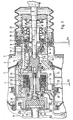
- Fig. 1 In the partial vacuum brake booster shown in Fig. 1 is the amplifier housing 1 by a axially movable wall 2 in a working chamber 3 and Vacuum chamber 4 divided.
- One by one Actuating rod 5 actuatable control valve 6 is in one guided in the amplifier housing 1 sealed, the movable Wall 2 carrying control housing 7 housed.
- the Control valve 6 contains a first sealing seat 8 am Control housing 7, a second sealing seat 9 on one with the Actuating rod 5 connected valve piston 10 and one interacting with the two sealing seats 8.9 valve body 11, which is by means of a retaining ring 12 supporting valve spring 13 against the sealing seats 8.9 is pressed.
- the working chamber 3 is with the Vacuum chamber 4 via a laterally in the control housing 7 extending channel 14 connectable. To the working chamber 3 at the actuation of the control valve 6 with the atmosphere to be able to connect is finally in the control housing 7 radially extending channel 15 is formed.
- the braking force is applied to a front part 16 of the Control housing 7 abutting rubber-elastic front Reaction disc 17 and a push rod 18 on one Actuating piston of a not shown Transfer master cylinder. Via a return spring 19 the movable wall 2 is in its initial position pressed.
- a second compression spring 20 is provided the one hand on the operating rod 5 and the other is supported on the retaining ring 12.
- Electromagnet 22 formed sleeve 23.
- the Electromagnet 22 consists of one in one with the Control piston 10 connected guide part 24 arranged Coil 25 and an armature 26 slidable therein, which with the sleeve 23 is in a force-transmitting connection.
- a closure part 27 arranged at the Front side of the guide part 24.
- a translator disk 28 is limited slidably arranged, their movement against the Direction of actuation by a trained in the front part 16 Annular surface 29 is limited.
- a brake booster with such a structure is in detail in WO 94/11226 mentioned at the beginning described. For more details, therefore, refer to this Reference printed.
- the brake booster in contrast to the well-known brake booster the brake booster according to the invention by a Sensor 30 for detecting the relative displacement between the Control housing 7 and the valve piston 10.
- the sensor 30 is a non-contact Sensor with a first sensor element 31 on the with Valve piston 10 fixedly connected guide part 24 and one second sensor element 32, which corresponds to the first sensor element 28 opposite one on the inner wall with the Control housing 7 fixed part 33 is arranged.
- Such a sensor enables a very simple one Control of the brake assist function, since the signal of the Sensor for both activating and deactivating the Electromagnets and thus the brake assistant used can be. This means that the Brake Assist mode based only on signals from a single one Sensor triggered and can also be ended.
- Fig. 2 is a diagram showing an example of the electrical control of the invention Brake booster depending on the through the Sensor 30 shows detected relative displacement.
- Point A is a state in which diagram is indicated the valve piston 10 in its maximum retracted Position opposite the control housing 7.
- This State can be achieved by solenoid 22 is energized without the driver's foot. This will make the Sliding sleeve 23 from anchor 26 according to FIG. 1 to the right moved and presses with its sealing seat 21 den Valve body 11 to the rear. This allows air from outside flow into the working chamber 3, the control housing 7 due to the pressure difference between the working chamber 3 and the vacuum chamber 4 is moved forward.
- the Valve piston 10 initially stops until it is from Control housing 7 is taken over the cross bar 34. This position in which the valve piston 10 is in its maximum retracted position relative to the timing case 7, can be used as the zero point of the sensor 30 (point A) be determined.
- the driver in the brake assist mode the previously reduced Increase the brake pressure again, so it increases the foot power until the foot power proportion analogous to the conventional one Brake booster function proportional to the pressure of the Master cylinder is, creating a smooth transition to regular braking function is achieved. If the driver arrives at the Brake assist mode with previously reduced brake pressure into a panic situation again, so the electromagnet after exceeding the activation threshold again with the full inrush current, which again the full reinforcement is provided.
- Fig. 3 is a circuit diagram of a simple electrical Circuit 40 for controlling the invention Brake booster shown.
- the circuit has two Comparators 41 and 42. To one of the entrances to the two Comparators 41 and 42 are each the signal of the Relative displacement between the control housing 7 and the Valve piston 10 detecting sensor 30 is applied. To the The comparison input of the first comparator 41 is one of the Switch-off threshold SW-2 in Fig. 2 corresponding signal and on the comparison input of the second comparator 42 one of the Switch-on threshold SW-1 corresponding signal applied.
- Both Comparators 41 and 42 each control via a transistor 43 and 44 a solenoid 45 and 46 of a relay 47 and 48 respectively on.
- the switches 49 and 50 of the relays 47 and 48 are in Series connected to the electromagnet 22.
- switch 50 remains closed because the solenoid 46 via the diode 51st continues to be powered. Only when the signal from the Sensor 30 falls below the switch-off threshold SW-2 power supply to relay 48 through relay 47 interrupted. This will energize the Electromagnet 22 interrupted and the brake assist mode disabled. To reactivate the Brake assist mode must return the signal from sensor 30 accept the value of switch-on threshold SW-1.
- the brake booster according to the invention can thus a very simple electrical circuit Activation and deactivation of the brake assist controlled become. Such a circuit does not require anything else Control unit and can be connected directly to the brake booster proceed or be integrated into this.
- Control unit can be connected directly to the brake booster proceed or be integrated into this.
Landscapes
- Engineering & Computer Science (AREA)
- Transportation (AREA)
- Mechanical Engineering (AREA)
- Braking Systems And Boosters (AREA)
Description
- Fig. 1
- eine Teilansicht eines erfindungsgemäßen Bremskraft-verstärkers mit aktiviertem Bremsassistenten im Längsschnitt;
- Fig. 2
- ein Diagramm zur Darstellung einer elektrischen Ansteuerung des erfindungsgemäßen Bremskraftverstärkers; und
- Fig. 3
- eine elektrische Schaltung zur Ansteuerung des Elektromagneten im erfindungsgemäßen Bremskraftverstärker.
Claims (14)
- Bremskraftverstärker für Kraftfahrzeuge mit einem Verstärkergehäuse (1), dessen Innenraum durch eine bewegliche Wand (2) in eine Arbeitskammer (3) und eine Unterdruckkammer (4) unterteilt ist, und einem die bewegliche Wand (2) tragenden Steuergehäuse (7), in dem ein sowohl durch eine Betätigungsstange (5) mittels eines Ventilkolbens (10) als auch durch einen Elektromagneten (22) betätigbares Steuerventil (6) zur Steuerung einer auf die bewegliche Wand (2) einwirkenden Druckdifferenz angeordnet ist, wobei ein Sensor vorhanden ist, der zur Ansteuerung des Electromagneten verwendet wird, dadurch gekennzeichnet, daß der Sensor (30) die Relativverschiebung zwischen dem Ventilkolben (10) und dem Steuergehäuse (7) erfaßt und in Abhängigkeit davon der Elektromagnet (22) aktiviert und gesteuert wird.
- Bremskraftverstärker nach Anspruch 1, dadurch gekennzeichnet, daß der Elektromagnet (22) bei Überschreiten einer vorgegebenen ersten Relativverschiebung aktivierbar ist.
- Bremskraftverstärker nach Anspruch 1 oder 2, dadurch gekennzeichnet, daß der Elektromagnet (22) bei Unterschreiten einer vorgegebenen zweiten Relativverschiebung deaktivierbar ist.
- Bremskraftverstärker nach Anspruch 2 oder 3, dadurch gekennzeichnet, daß der Ansteuerstrom des Elektromagneten (22) im aktivierten Zustand in Abhängigkeit von der durch den Sensor (30) erfaßten Relativverschiebung oder einem Relativverschiebungsgradienten veränderbar ist.
- Bremskraftverstärker nach einem der Ansprüche 2 bis 4, dadurch gekennzeichnet, daß die zur Aktivierung des Elektromagneten (22) vorgegebene erste Relativverschiebung in Abhängigkeit von der Fahrzeugverzögerung und/oder der Fahrzeuggeschwindigkeit und/oder des Bremsdrucks und/oder der Zeit, die nach dem Zeitpunkt der Pedalbetätigung vergangen ist, veränderbar ist.
- Bremskraftverstärker nach einem der vorhergehenden Ansprüche, dadurch gekennzeichnet, daß der Sensor (30) ein berührungsloser Wegsensor ist.
- Bremskraftverstärker nach einem der vorhergehenden Ansprüche, dadurch gekennzeichnet, daß der Sensor (30) ein erstes Sensorelement (31) an einem mit dem Ventilkolben (10) fest verbundenen Führungsteil (24) sowie ein zweites Sensorelement (32) an einem mit dem Steuergehäuse (7) verbundenen Teil (33) enthält.
- Bremskraftverstärker nach einem der vorhergehenden Ansprüche, dadurch gekennzeichnet, daß der Sensor (30) ein Hallsensor ist.
- Bremskraftverstärker nach einem der vorhergehenden Ansprüche, dadurch gekennzeichnet, daß eine elektronische Ansteuereinrichtung (40) vorgesehen ist, die nach Maßgabe der Ausgangssignale des Sensors (22) den Elektromagneten (30) ansteuert.
- Bremskraftverstärker nach einem der vorhergehenden Ansprüche, dadurch gekennzeichnet, daß die elektronische Ansteuereinrichtung (40) zwei Komparatoren (41,42) enthält, wobei an einen der Eingänge der beiden Komparatoren (41,42) jeweils das Signal des Sensors (22) und an den Vergleichseingang eines der beiden Komparatoren (41) ein Signal angelegt ist, das einer Abschaltschwelle (SW-2) entspricht, und an den Vergleichseingang des anderen Komparators (42) ein Signal angelegt ist, das einer Zuschaltschwelle (SW-1) entspricht.
- Bremskraftverstärker nach Anspruch 10, dadurch gekennzeichnet, daß die beiden Komparatoren (41,42) jeweils über einen Transistor (43,44) ein Relais (47,48) ansteuern, wobei die Relais (47,48) in Reihe zum Elektromagneten (22) geschaltet sind.
- Bremskraftverstärker nach Anspruch 11, dadurch gekennzeichnet, daß an einer Verbindungsleitung zwischen dem Schalter (50) des Relais (48) und dem Elekromagneten (22) eine zur Eingangseite der Magnetspule (46) des Relais (48) führende Verbindungsleitung anzeigt, in der eine Diode (51) angeordnet ist.
- Verfahren zur Ansteuerung eines Bremskraftverstärkers nach einem der Ansprüche 1 bis 12, dadurch gekennzeichnet, daß der Elektromagnet (22) aktiviert wird, wenn das Signal des Sensors (30) gleich oder größer als eine Zuschaltschwelle (SW-1) ist und daß der Elektromagnet (22) deaktiviert wird, wenn das Signal des Sensors (30) kleiner als eine Abschaltschwelle (SW-2) ist, wobei die Abschaltschwelle kleiner als die Zuschaltschwelle ist.
- Verfahren nach Anspruch 13, dadurch gekennzeichnet, daß der Ansteuerstrom des Elektromagneten (22) im aktivierten Zustand in Abhängigkeit von der durch den Sensor (30) erfaßten Relativverschiebung oder einem Relativverschiebungsgradienten gesteuert wird.
Applications Claiming Priority (5)
| Application Number | Priority Date | Filing Date | Title |
|---|---|---|---|
| DE19804936 | 1998-02-07 | ||
| DE19804936 | 1998-02-07 | ||
| DE19841879A DE19841879A1 (de) | 1998-02-07 | 1998-09-11 | Bremskraftverstärker und Verfahren zu seiner Ansteuerung |
| DE19841879 | 1998-09-11 | ||
| PCT/EP1999/000721 WO1999039958A1 (de) | 1998-02-07 | 1999-02-04 | Bremskraftverstärker und verfahren zu seiner ansteuerung |
Publications (2)
| Publication Number | Publication Date |
|---|---|
| EP1053156A1 EP1053156A1 (de) | 2000-11-22 |
| EP1053156B1 true EP1053156B1 (de) | 2002-10-30 |
Family
ID=26043701
Family Applications (1)
| Application Number | Title | Priority Date | Filing Date |
|---|---|---|---|
| EP99906217A Expired - Lifetime EP1053156B1 (de) | 1998-02-07 | 1999-02-04 | Bremskraftverstärker und verfahren zu seiner ansteuerung |
Country Status (6)
| Country | Link |
|---|---|
| US (1) | US6516701B1 (de) |
| EP (1) | EP1053156B1 (de) |
| JP (1) | JP2002502756A (de) |
| AT (1) | ATE226904T1 (de) |
| AU (1) | AU2622599A (de) |
| WO (1) | WO1999039958A1 (de) |
Families Citing this family (3)
| Publication number | Priority date | Publication date | Assignee | Title |
|---|---|---|---|---|
| US7267412B2 (en) * | 2002-02-07 | 2007-09-11 | Continental Teves Ag & Co. Ohg | Method for determining or calibrating the brake control characteristic of a vacuum brake booster |
| CN102060009B (zh) * | 2010-12-10 | 2013-04-17 | 清华大学 | 一种具有电子辅助制动功能的制动系统 |
| CN103802814B (zh) | 2012-11-13 | 2017-05-31 | 博世汽车部件(苏州)有限公司 | 制动助力器 |
Family Cites Families (7)
| Publication number | Priority date | Publication date | Assignee | Title |
|---|---|---|---|---|
| US3856105A (en) * | 1972-09-25 | 1974-12-24 | R Lewis | Vehicle brake system having foot pedal operated brake actuator with electronic range control |
| JPS60166552A (ja) * | 1984-02-08 | 1985-08-29 | Nissan Motor Co Ltd | ブレ−キ倍力装置 |
| AU4541385A (en) * | 1985-02-14 | 1986-09-10 | Fail Safe Brake Corp. | Vehicle brake actuator arrangement |
| CZ281175B6 (cs) * | 1992-11-13 | 1996-07-17 | Itt Automotive Europe Gmbh | Podtlakový posilovač brzd |
| DE4324688A1 (de) | 1993-07-23 | 1995-01-26 | Teves Gmbh Alfred | Unterdruckbremskraftverstärker |
| DE19508822A1 (de) | 1995-03-11 | 1996-09-12 | Teves Gmbh Alfred | Bremsanlage für Kraftfahrzeuge |
| DE19519874A1 (de) * | 1995-05-31 | 1996-12-05 | Teves Gmbh Alfred | Unterdruckbremskraftverstärker |
-
1999
- 1999-02-04 US US09/601,780 patent/US6516701B1/en not_active Expired - Fee Related
- 1999-02-04 EP EP99906217A patent/EP1053156B1/de not_active Expired - Lifetime
- 1999-02-04 JP JP2000530409A patent/JP2002502756A/ja not_active Ceased
- 1999-02-04 AU AU26225/99A patent/AU2622599A/en not_active Abandoned
- 1999-02-04 AT AT99906217T patent/ATE226904T1/de not_active IP Right Cessation
- 1999-02-04 WO PCT/EP1999/000721 patent/WO1999039958A1/de not_active Ceased
Also Published As
| Publication number | Publication date |
|---|---|
| US6516701B1 (en) | 2003-02-11 |
| AU2622599A (en) | 1999-08-23 |
| EP1053156A1 (de) | 2000-11-22 |
| ATE226904T1 (de) | 2002-11-15 |
| WO1999039958A1 (de) | 1999-08-12 |
| JP2002502756A (ja) | 2002-01-29 |
Similar Documents
| Publication | Publication Date | Title |
|---|---|---|
| EP1638830B1 (de) | Elektromechanischer bremskraftverstärker | |
| EP0620789B1 (de) | Unterdruckbremskraftverstärker | |
| EP3368387B1 (de) | Elektro-pneumatische feststellbremseinrichtung mit redundanter pneumatischer steuerung | |
| EP0633850A1 (de) | Pneumatischer kraftverstärker mit elektromagnetischer hilfssteuerung, insbesondere für kraftfahrzeug-bremsanlagen. | |
| EP0711695A2 (de) | Elektronisch gesteuerte Fahrzeugbremsanlage und Verfahren zu deren Betrieb | |
| EP3585663B1 (de) | Bremssystem für ein fahrzeug mit einer hydraulischen fahrzeugbremse und mit einer elektromechanischen bremsvorrichtung | |
| DE10057557A1 (de) | Elektromechanischer Bremskraftverstärker | |
| DE102007016864A1 (de) | Bremssystem für ein Fahrzeug | |
| DE4410699C2 (de) | Hydraulische Bremsanlage für Kraftfahrzeuge | |
| DE102016010823A1 (de) | Technik zum Ermitteln der Lage eines Abstützpunktes einer Feststellbremseinheit | |
| DE4324688A1 (de) | Unterdruckbremskraftverstärker | |
| DE102011083112A1 (de) | Bremsvorrichtung | |
| WO2010069656A1 (de) | Verfahren zur steuerung eines bremskraftverstärkers einer hydraulischen hilfskraft-fahrzeugbremsanlage | |
| DE2347689C2 (de) | Bremsanlage für Kraftfahrzeuge zum radargesteuerten Anlegen der Bremse | |
| DE69306812T2 (de) | Unterdruckbremskraftverstärker | |
| EP0781221B1 (de) | Fahrzeugbremsanlage mit einem elektronisch gesteuerten bremskraftverstärker | |
| DE60003270T2 (de) | Bremskraftverstärker | |
| EP0886595B1 (de) | Pneumatischer bremskraftverstärker | |
| DE19817589A1 (de) | Unterdruckbremskraftverstärker für ein Fahrzeug | |
| WO2004089713A1 (de) | Verfahren zum betrieb eines hydraulischen bremssystems mit integrierter feststellbremsfunktion für kraftfahrzeuge | |
| DE102016218214A1 (de) | Bremssystem-Steuergerät für ein Fahrzeug | |
| EP0915787A2 (de) | Bremsvorrichtung | |
| EP2296948B1 (de) | Bremskraftverstärker für eine kraftfahrzeugbremsanlage und entsprechende kraftfahrzeugbremsanlage | |
| DE19845052A1 (de) | Bremssystem | |
| EP1053156A1 (de) | Bremskraftverstärker und verfahren zu seiner ansteuerung |
Legal Events
| Date | Code | Title | Description |
|---|---|---|---|
| PUAI | Public reference made under article 153(3) epc to a published international application that has entered the european phase |
Free format text: ORIGINAL CODE: 0009012 |
|
| 17P | Request for examination filed |
Effective date: 20000907 |
|
| AK | Designated contracting states |
Kind code of ref document: A1 Designated state(s): AT BE CH CY DE DK ES FI FR GB GR IE IT LI LU MC NL PT SE |
|
| GRAG | Despatch of communication of intention to grant |
Free format text: ORIGINAL CODE: EPIDOS AGRA |
|
| 17Q | First examination report despatched |
Effective date: 20020123 |
|
| GRAG | Despatch of communication of intention to grant |
Free format text: ORIGINAL CODE: EPIDOS AGRA |
|
| GRAH | Despatch of communication of intention to grant a patent |
Free format text: ORIGINAL CODE: EPIDOS IGRA |
|
| GRAH | Despatch of communication of intention to grant a patent |
Free format text: ORIGINAL CODE: EPIDOS IGRA |
|
| GRAA | (expected) grant |
Free format text: ORIGINAL CODE: 0009210 |
|
| AK | Designated contracting states |
Kind code of ref document: B1 Designated state(s): AT BE CH CY DE DK ES FI FR GB GR IE IT LI LU MC NL PT SE |
|
| PG25 | Lapsed in a contracting state [announced via postgrant information from national office to epo] |
Ref country code: NL Free format text: LAPSE BECAUSE OF FAILURE TO SUBMIT A TRANSLATION OF THE DESCRIPTION OR TO PAY THE FEE WITHIN THE PRESCRIBED TIME-LIMIT Effective date: 20021030 Ref country code: IE Free format text: LAPSE BECAUSE OF FAILURE TO SUBMIT A TRANSLATION OF THE DESCRIPTION OR TO PAY THE FEE WITHIN THE PRESCRIBED TIME-LIMIT Effective date: 20021030 Ref country code: GR Free format text: LAPSE BECAUSE OF FAILURE TO SUBMIT A TRANSLATION OF THE DESCRIPTION OR TO PAY THE FEE WITHIN THE PRESCRIBED TIME-LIMIT Effective date: 20021030 Ref country code: GB Free format text: LAPSE BECAUSE OF FAILURE TO SUBMIT A TRANSLATION OF THE DESCRIPTION OR TO PAY THE FEE WITHIN THE PRESCRIBED TIME-LIMIT Effective date: 20021030 Ref country code: FI Free format text: LAPSE BECAUSE OF FAILURE TO SUBMIT A TRANSLATION OF THE DESCRIPTION OR TO PAY THE FEE WITHIN THE PRESCRIBED TIME-LIMIT Effective date: 20021030 |
|
| REF | Corresponds to: |
Ref document number: 226904 Country of ref document: AT Date of ref document: 20021115 Kind code of ref document: T |
|
| REG | Reference to a national code |
Ref country code: GB Ref legal event code: FG4D Free format text: NOT ENGLISH |
|
| REG | Reference to a national code |
Ref country code: CH Ref legal event code: EP |
|
| REG | Reference to a national code |
Ref country code: IE Ref legal event code: FG4D Free format text: GERMAN |
|
| REF | Corresponds to: |
Ref document number: 59903248 Country of ref document: DE Date of ref document: 20021205 |
|
| PG25 | Lapsed in a contracting state [announced via postgrant information from national office to epo] |
Ref country code: SE Free format text: LAPSE BECAUSE OF FAILURE TO SUBMIT A TRANSLATION OF THE DESCRIPTION OR TO PAY THE FEE WITHIN THE PRESCRIBED TIME-LIMIT Effective date: 20030130 Ref country code: PT Free format text: LAPSE BECAUSE OF FAILURE TO SUBMIT A TRANSLATION OF THE DESCRIPTION OR TO PAY THE FEE WITHIN THE PRESCRIBED TIME-LIMIT Effective date: 20030130 Ref country code: DK Free format text: LAPSE BECAUSE OF FAILURE TO SUBMIT A TRANSLATION OF THE DESCRIPTION OR TO PAY THE FEE WITHIN THE PRESCRIBED TIME-LIMIT Effective date: 20030130 |
|
| PG25 | Lapsed in a contracting state [announced via postgrant information from national office to epo] |
Ref country code: LU Free format text: LAPSE BECAUSE OF NON-PAYMENT OF DUE FEES Effective date: 20030204 Ref country code: CY Free format text: LAPSE BECAUSE OF FAILURE TO SUBMIT A TRANSLATION OF THE DESCRIPTION OR TO PAY THE FEE WITHIN THE PRESCRIBED TIME-LIMIT Effective date: 20030204 Ref country code: AT Free format text: LAPSE BECAUSE OF NON-PAYMENT OF DUE FEES Effective date: 20030204 |
|
| PG25 | Lapsed in a contracting state [announced via postgrant information from national office to epo] |
Ref country code: MC Free format text: LAPSE BECAUSE OF NON-PAYMENT OF DUE FEES Effective date: 20030228 Ref country code: LI Free format text: LAPSE BECAUSE OF NON-PAYMENT OF DUE FEES Effective date: 20030228 Ref country code: CH Free format text: LAPSE BECAUSE OF NON-PAYMENT OF DUE FEES Effective date: 20030228 Ref country code: BE Free format text: LAPSE BECAUSE OF NON-PAYMENT OF DUE FEES Effective date: 20030228 |
|
| NLV1 | Nl: lapsed or annulled due to failure to fulfill the requirements of art. 29p and 29m of the patents act | ||
| PG25 | Lapsed in a contracting state [announced via postgrant information from national office to epo] |
Ref country code: ES Free format text: LAPSE BECAUSE OF FAILURE TO SUBMIT A TRANSLATION OF THE DESCRIPTION OR TO PAY THE FEE WITHIN THE PRESCRIBED TIME-LIMIT Effective date: 20030429 |
|
| GBV | Gb: ep patent (uk) treated as always having been void in accordance with gb section 77(7)/1977 [no translation filed] |
Effective date: 20021030 |
|
| ET | Fr: translation filed | ||
| REG | Reference to a national code |
Ref country code: IE Ref legal event code: FD4D Ref document number: 1053156E Country of ref document: IE |
|
| PLBE | No opposition filed within time limit |
Free format text: ORIGINAL CODE: 0009261 |
|
| STAA | Information on the status of an ep patent application or granted ep patent |
Free format text: STATUS: NO OPPOSITION FILED WITHIN TIME LIMIT |
|
| REG | Reference to a national code |
Ref country code: CH Ref legal event code: PL |
|
| 26N | No opposition filed |
Effective date: 20030731 |
|
| PG25 | Lapsed in a contracting state [announced via postgrant information from national office to epo] |
Ref country code: IT Free format text: LAPSE BECAUSE OF NON-PAYMENT OF DUE FEES;WARNING: LAPSES OF ITALIAN PATENTS WITH EFFECTIVE DATE BEFORE 2007 MAY HAVE OCCURRED AT ANY TIME BEFORE 2007. THE CORRECT EFFECTIVE DATE MAY BE DIFFERENT FROM THE ONE RECORDED. Effective date: 20050204 |
|
| PG25 | Lapsed in a contracting state [announced via postgrant information from national office to epo] |
Ref country code: FR Free format text: LAPSE BECAUSE OF NON-PAYMENT OF DUE FEES Effective date: 20060630 |
|
| REG | Reference to a national code |
Ref country code: FR Ref legal event code: ST Effective date: 20060630 |
|
| REG | Reference to a national code |
Ref country code: FR Ref legal event code: RN |
|
| REG | Reference to a national code |
Ref country code: FR Ref legal event code: IC |
|
| PG25 | Lapsed in a contracting state [announced via postgrant information from national office to epo] |
Ref country code: DE Free format text: LAPSE BECAUSE OF THE APPLICANT RENOUNCES Effective date: 20080312 |
|
| PGFP | Annual fee paid to national office [announced via postgrant information from national office to epo] |
Ref country code: DE Payment date: 20080229 Year of fee payment: 10 |
|
| PG25 | Lapsed in a contracting state [announced via postgrant information from national office to epo] |
Ref country code: FR Free format text: LAPSE BECAUSE OF NON-PAYMENT OF DUE FEES Effective date: 20030228 |
|
| PGFP | Annual fee paid to national office [announced via postgrant information from national office to epo] |
Ref country code: IT Payment date: 20080221 Year of fee payment: 10 |
|
| PGRI | Patent reinstated in contracting state [announced from national office to epo] |
Ref country code: IT Effective date: 20091201 |
|
| PGRI | Patent reinstated in contracting state [announced from national office to epo] |
Ref country code: IT Effective date: 20091201 |