EP1047141A2 - Formstabile schmelzbare Batterieseparatoren und Herstellungsverfahren - Google Patents
Formstabile schmelzbare Batterieseparatoren und Herstellungsverfahren Download PDFInfo
- Publication number
- EP1047141A2 EP1047141A2 EP20000108315 EP00108315A EP1047141A2 EP 1047141 A2 EP1047141 A2 EP 1047141A2 EP 20000108315 EP20000108315 EP 20000108315 EP 00108315 A EP00108315 A EP 00108315A EP 1047141 A2 EP1047141 A2 EP 1047141A2
- Authority
- EP
- European Patent Office
- Prior art keywords
- battery separator
- polypropylene
- layer
- membrane
- polymer film
- Prior art date
- Legal status (The legal status is an assumption and is not a legal conclusion. Google has not performed a legal analysis and makes no representation as to the accuracy of the status listed.)
- Withdrawn
Links
Images


Classifications
-
- B—PERFORMING OPERATIONS; TRANSPORTING
- B29—WORKING OF PLASTICS; WORKING OF SUBSTANCES IN A PLASTIC STATE IN GENERAL
- B29C—SHAPING OR JOINING OF PLASTICS; SHAPING OF MATERIAL IN A PLASTIC STATE, NOT OTHERWISE PROVIDED FOR; AFTER-TREATMENT OF THE SHAPED PRODUCTS, e.g. REPAIRING
- B29C55/00—Shaping by stretching, e.g. drawing through a die; Apparatus therefor
- B29C55/005—Shaping by stretching, e.g. drawing through a die; Apparatus therefor characterised by the choice of materials
-
- H—ELECTRICITY
- H01—ELECTRIC ELEMENTS
- H01M—PROCESSES OR MEANS, e.g. BATTERIES, FOR THE DIRECT CONVERSION OF CHEMICAL ENERGY INTO ELECTRICAL ENERGY
- H01M50/00—Constructional details or processes of manufacture of the non-active parts of electrochemical cells other than fuel cells, e.g. hybrid cells
- H01M50/40—Separators; Membranes; Diaphragms; Spacing elements inside cells
- H01M50/409—Separators, membranes or diaphragms characterised by the material
- H01M50/449—Separators, membranes or diaphragms characterised by the material having a layered structure
-
- B—PERFORMING OPERATIONS; TRANSPORTING
- B29—WORKING OF PLASTICS; WORKING OF SUBSTANCES IN A PLASTIC STATE IN GENERAL
- B29C—SHAPING OR JOINING OF PLASTICS; SHAPING OF MATERIAL IN A PLASTIC STATE, NOT OTHERWISE PROVIDED FOR; AFTER-TREATMENT OF THE SHAPED PRODUCTS, e.g. REPAIRING
- B29C48/00—Extrusion moulding, i.e. expressing the moulding material through a die or nozzle which imparts the desired form; Apparatus therefor
- B29C48/03—Extrusion moulding, i.e. expressing the moulding material through a die or nozzle which imparts the desired form; Apparatus therefor characterised by the shape of the extruded material at extrusion
- B29C48/09—Articles with cross-sections having partially or fully enclosed cavities, e.g. pipes or channels
- B29C48/10—Articles with cross-sections having partially or fully enclosed cavities, e.g. pipes or channels flexible, e.g. blown foils
-
- B—PERFORMING OPERATIONS; TRANSPORTING
- B29—WORKING OF PLASTICS; WORKING OF SUBSTANCES IN A PLASTIC STATE IN GENERAL
- B29C—SHAPING OR JOINING OF PLASTICS; SHAPING OF MATERIAL IN A PLASTIC STATE, NOT OTHERWISE PROVIDED FOR; AFTER-TREATMENT OF THE SHAPED PRODUCTS, e.g. REPAIRING
- B29C48/00—Extrusion moulding, i.e. expressing the moulding material through a die or nozzle which imparts the desired form; Apparatus therefor
- B29C48/25—Component parts, details or accessories; Auxiliary operations
- B29C48/88—Thermal treatment of the stream of extruded material, e.g. cooling
- B29C48/91—Heating, e.g. for cross linking
-
- B—PERFORMING OPERATIONS; TRANSPORTING
- B29—WORKING OF PLASTICS; WORKING OF SUBSTANCES IN A PLASTIC STATE IN GENERAL
- B29C—SHAPING OR JOINING OF PLASTICS; SHAPING OF MATERIAL IN A PLASTIC STATE, NOT OTHERWISE PROVIDED FOR; AFTER-TREATMENT OF THE SHAPED PRODUCTS, e.g. REPAIRING
- B29C48/00—Extrusion moulding, i.e. expressing the moulding material through a die or nozzle which imparts the desired form; Apparatus therefor
- B29C48/25—Component parts, details or accessories; Auxiliary operations
- B29C48/88—Thermal treatment of the stream of extruded material, e.g. cooling
- B29C48/911—Cooling
- B29C48/9115—Cooling of hollow articles
- B29C48/912—Cooling of hollow articles of tubular films
- B29C48/9125—Cooling of hollow articles of tubular films internally
-
- B—PERFORMING OPERATIONS; TRANSPORTING
- B29—WORKING OF PLASTICS; WORKING OF SUBSTANCES IN A PLASTIC STATE IN GENERAL
- B29C—SHAPING OR JOINING OF PLASTICS; SHAPING OF MATERIAL IN A PLASTIC STATE, NOT OTHERWISE PROVIDED FOR; AFTER-TREATMENT OF THE SHAPED PRODUCTS, e.g. REPAIRING
- B29C48/00—Extrusion moulding, i.e. expressing the moulding material through a die or nozzle which imparts the desired form; Apparatus therefor
- B29C48/25—Component parts, details or accessories; Auxiliary operations
- B29C48/88—Thermal treatment of the stream of extruded material, e.g. cooling
- B29C48/911—Cooling
- B29C48/9115—Cooling of hollow articles
- B29C48/912—Cooling of hollow articles of tubular films
- B29C48/913—Cooling of hollow articles of tubular films externally
-
- B—PERFORMING OPERATIONS; TRANSPORTING
- B32—LAYERED PRODUCTS
- B32B—LAYERED PRODUCTS, i.e. PRODUCTS BUILT-UP OF STRATA OF FLAT OR NON-FLAT, e.g. CELLULAR OR HONEYCOMB, FORM
- B32B27/00—Layered products comprising a layer of synthetic resin
- B32B27/32—Layered products comprising a layer of synthetic resin comprising polyolefins
-
- H—ELECTRICITY
- H01—ELECTRIC ELEMENTS
- H01M—PROCESSES OR MEANS, e.g. BATTERIES, FOR THE DIRECT CONVERSION OF CHEMICAL ENERGY INTO ELECTRICAL ENERGY
- H01M50/00—Constructional details or processes of manufacture of the non-active parts of electrochemical cells other than fuel cells, e.g. hybrid cells
- H01M50/40—Separators; Membranes; Diaphragms; Spacing elements inside cells
- H01M50/403—Manufacturing processes of separators, membranes or diaphragms
- H01M50/406—Moulding; Embossing; Cutting
-
- H—ELECTRICITY
- H01—ELECTRIC ELEMENTS
- H01M—PROCESSES OR MEANS, e.g. BATTERIES, FOR THE DIRECT CONVERSION OF CHEMICAL ENERGY INTO ELECTRICAL ENERGY
- H01M50/00—Constructional details or processes of manufacture of the non-active parts of electrochemical cells other than fuel cells, e.g. hybrid cells
- H01M50/40—Separators; Membranes; Diaphragms; Spacing elements inside cells
- H01M50/409—Separators, membranes or diaphragms characterised by the material
- H01M50/411—Organic material
- H01M50/414—Synthetic resins, e.g. thermoplastics or thermosetting resins
- H01M50/417—Polyolefins
-
- H—ELECTRICITY
- H01—ELECTRIC ELEMENTS
- H01M—PROCESSES OR MEANS, e.g. BATTERIES, FOR THE DIRECT CONVERSION OF CHEMICAL ENERGY INTO ELECTRICAL ENERGY
- H01M50/00—Constructional details or processes of manufacture of the non-active parts of electrochemical cells other than fuel cells, e.g. hybrid cells
- H01M50/40—Separators; Membranes; Diaphragms; Spacing elements inside cells
- H01M50/409—Separators, membranes or diaphragms characterised by the material
- H01M50/449—Separators, membranes or diaphragms characterised by the material having a layered structure
- H01M50/451—Separators, membranes or diaphragms characterised by the material having a layered structure comprising layers of only organic material and layers containing inorganic material
-
- H—ELECTRICITY
- H01—ELECTRIC ELEMENTS
- H01M—PROCESSES OR MEANS, e.g. BATTERIES, FOR THE DIRECT CONVERSION OF CHEMICAL ENERGY INTO ELECTRICAL ENERGY
- H01M50/00—Constructional details or processes of manufacture of the non-active parts of electrochemical cells other than fuel cells, e.g. hybrid cells
- H01M50/40—Separators; Membranes; Diaphragms; Spacing elements inside cells
- H01M50/409—Separators, membranes or diaphragms characterised by the material
- H01M50/449—Separators, membranes or diaphragms characterised by the material having a layered structure
- H01M50/457—Separators, membranes or diaphragms characterised by the material having a layered structure comprising three or more layers
-
- H—ELECTRICITY
- H01—ELECTRIC ELEMENTS
- H01M—PROCESSES OR MEANS, e.g. BATTERIES, FOR THE DIRECT CONVERSION OF CHEMICAL ENERGY INTO ELECTRICAL ENERGY
- H01M50/00—Constructional details or processes of manufacture of the non-active parts of electrochemical cells other than fuel cells, e.g. hybrid cells
- H01M50/40—Separators; Membranes; Diaphragms; Spacing elements inside cells
- H01M50/489—Separators, membranes, diaphragms or spacing elements inside the cells, characterised by their physical properties, e.g. swelling degree, hydrophilicity or shut down properties
-
- B—PERFORMING OPERATIONS; TRANSPORTING
- B29—WORKING OF PLASTICS; WORKING OF SUBSTANCES IN A PLASTIC STATE IN GENERAL
- B29C—SHAPING OR JOINING OF PLASTICS; SHAPING OF MATERIAL IN A PLASTIC STATE, NOT OTHERWISE PROVIDED FOR; AFTER-TREATMENT OF THE SHAPED PRODUCTS, e.g. REPAIRING
- B29C71/00—After-treatment of articles without altering their shape; Apparatus therefor
- B29C71/02—Thermal after-treatment
- B29C2071/022—Annealing
-
- B—PERFORMING OPERATIONS; TRANSPORTING
- B29—WORKING OF PLASTICS; WORKING OF SUBSTANCES IN A PLASTIC STATE IN GENERAL
- B29C—SHAPING OR JOINING OF PLASTICS; SHAPING OF MATERIAL IN A PLASTIC STATE, NOT OTHERWISE PROVIDED FOR; AFTER-TREATMENT OF THE SHAPED PRODUCTS, e.g. REPAIRING
- B29C48/00—Extrusion moulding, i.e. expressing the moulding material through a die or nozzle which imparts the desired form; Apparatus therefor
- B29C48/03—Extrusion moulding, i.e. expressing the moulding material through a die or nozzle which imparts the desired form; Apparatus therefor characterised by the shape of the extruded material at extrusion
- B29C48/09—Articles with cross-sections having partially or fully enclosed cavities, e.g. pipes or channels
-
- B—PERFORMING OPERATIONS; TRANSPORTING
- B29—WORKING OF PLASTICS; WORKING OF SUBSTANCES IN A PLASTIC STATE IN GENERAL
- B29C—SHAPING OR JOINING OF PLASTICS; SHAPING OF MATERIAL IN A PLASTIC STATE, NOT OTHERWISE PROVIDED FOR; AFTER-TREATMENT OF THE SHAPED PRODUCTS, e.g. REPAIRING
- B29C48/00—Extrusion moulding, i.e. expressing the moulding material through a die or nozzle which imparts the desired form; Apparatus therefor
- B29C48/16—Articles comprising two or more components, e.g. co-extruded layers
- B29C48/18—Articles comprising two or more components, e.g. co-extruded layers the components being layers
- B29C48/21—Articles comprising two or more components, e.g. co-extruded layers the components being layers the layers being joined at their surfaces
-
- B—PERFORMING OPERATIONS; TRANSPORTING
- B29—WORKING OF PLASTICS; WORKING OF SUBSTANCES IN A PLASTIC STATE IN GENERAL
- B29C—SHAPING OR JOINING OF PLASTICS; SHAPING OF MATERIAL IN A PLASTIC STATE, NOT OTHERWISE PROVIDED FOR; AFTER-TREATMENT OF THE SHAPED PRODUCTS, e.g. REPAIRING
- B29C48/00—Extrusion moulding, i.e. expressing the moulding material through a die or nozzle which imparts the desired form; Apparatus therefor
- B29C48/25—Component parts, details or accessories; Auxiliary operations
- B29C48/30—Extrusion nozzles or dies
- B29C48/32—Extrusion nozzles or dies with annular openings, e.g. for forming tubular articles
- B29C48/335—Multiple annular extrusion nozzles in coaxial arrangement, e.g. for making multi-layered tubular articles
-
- B—PERFORMING OPERATIONS; TRANSPORTING
- B29—WORKING OF PLASTICS; WORKING OF SUBSTANCES IN A PLASTIC STATE IN GENERAL
- B29K—INDEXING SCHEME ASSOCIATED WITH SUBCLASSES B29B, B29C OR B29D, RELATING TO MOULDING MATERIALS OR TO MATERIALS FOR MOULDS, REINFORCEMENTS, FILLERS OR PREFORMED PARTS, e.g. INSERTS
- B29K2023/00—Use of polyalkenes or derivatives thereof as moulding material
- B29K2023/04—Polymers of ethylene
- B29K2023/06—PE, i.e. polyethylene
-
- B—PERFORMING OPERATIONS; TRANSPORTING
- B29—WORKING OF PLASTICS; WORKING OF SUBSTANCES IN A PLASTIC STATE IN GENERAL
- B29K—INDEXING SCHEME ASSOCIATED WITH SUBCLASSES B29B, B29C OR B29D, RELATING TO MOULDING MATERIALS OR TO MATERIALS FOR MOULDS, REINFORCEMENTS, FILLERS OR PREFORMED PARTS, e.g. INSERTS
- B29K2023/00—Use of polyalkenes or derivatives thereof as moulding material
- B29K2023/10—Polymers of propylene
- B29K2023/12—PP, i.e. polypropylene
-
- B—PERFORMING OPERATIONS; TRANSPORTING
- B29—WORKING OF PLASTICS; WORKING OF SUBSTANCES IN A PLASTIC STATE IN GENERAL
- B29K—INDEXING SCHEME ASSOCIATED WITH SUBCLASSES B29B, B29C OR B29D, RELATING TO MOULDING MATERIALS OR TO MATERIALS FOR MOULDS, REINFORCEMENTS, FILLERS OR PREFORMED PARTS, e.g. INSERTS
- B29K2105/00—Condition, form or state of moulded material or of the material to be shaped
- B29K2105/04—Condition, form or state of moulded material or of the material to be shaped cellular or porous
-
- B—PERFORMING OPERATIONS; TRANSPORTING
- B29—WORKING OF PLASTICS; WORKING OF SUBSTANCES IN A PLASTIC STATE IN GENERAL
- B29L—INDEXING SCHEME ASSOCIATED WITH SUBCLASS B29C, RELATING TO PARTICULAR ARTICLES
- B29L2031/00—Other particular articles
- B29L2031/34—Electrical apparatus, e.g. sparking plugs or parts thereof
- B29L2031/3468—Batteries, accumulators or fuel cells
-
- H—ELECTRICITY
- H01—ELECTRIC ELEMENTS
- H01M—PROCESSES OR MEANS, e.g. BATTERIES, FOR THE DIRECT CONVERSION OF CHEMICAL ENERGY INTO ELECTRICAL ENERGY
- H01M10/00—Secondary cells; Manufacture thereof
- H01M10/05—Accumulators with non-aqueous electrolyte
- H01M10/052—Li-accumulators
-
- H—ELECTRICITY
- H01—ELECTRIC ELEMENTS
- H01M—PROCESSES OR MEANS, e.g. BATTERIES, FOR THE DIRECT CONVERSION OF CHEMICAL ENERGY INTO ELECTRICAL ENERGY
- H01M50/00—Constructional details or processes of manufacture of the non-active parts of electrochemical cells other than fuel cells, e.g. hybrid cells
- H01M50/40—Separators; Membranes; Diaphragms; Spacing elements inside cells
- H01M50/489—Separators, membranes, diaphragms or spacing elements inside the cells, characterised by their physical properties, e.g. swelling degree, hydrophilicity or shut down properties
- H01M50/491—Porosity
-
- Y—GENERAL TAGGING OF NEW TECHNOLOGICAL DEVELOPMENTS; GENERAL TAGGING OF CROSS-SECTIONAL TECHNOLOGIES SPANNING OVER SEVERAL SECTIONS OF THE IPC; TECHNICAL SUBJECTS COVERED BY FORMER USPC CROSS-REFERENCE ART COLLECTIONS [XRACs] AND DIGESTS
- Y02—TECHNOLOGIES OR APPLICATIONS FOR MITIGATION OR ADAPTATION AGAINST CLIMATE CHANGE
- Y02E—REDUCTION OF GREENHOUSE GAS [GHG] EMISSIONS, RELATED TO ENERGY GENERATION, TRANSMISSION OR DISTRIBUTION
- Y02E60/00—Enabling technologies; Technologies with a potential or indirect contribution to GHG emissions mitigation
- Y02E60/10—Energy storage using batteries
Definitions
- the present invention relates to battery separators and particularly to battery separators exhibiting an extended high electrical resistance profile over temperatures to 180°C or more.
- Batteries separators may be prepared by various techniques, for example, by way of extraction, or by way of a multi-step annealing/stretching process. This latter process was discovered by the Celanese Plastics Company of Summit, New Jersey in the early 1970's.
- a crystalline polymer, such as polypropylene is first extruded into a film under conditions which enhance stress in the molten polymer. It is desirable to anneal the film in an untensioned or low tensioned state to perfect the necessary crystalline structure.
- the precursor thus prepared is elongated in the machine direction to introduce a network of slit-like voids.
- the deformation process may be used to control the pore size and pore size distribution as well as the overall porosity.
- United States Patent No. 4,650,730 to Lundquist et al. discloses a multiply polymeric sheet useful as a battery separator.
- the sheet includes a first layer in the form of a microporous sheet (unfilled) and a second, filled microporous sheet.
- the microporous component sheets are produced by an extraction process, then laminated together to form the structure, which will become non-porous at elevated temperatures.
- the claims specify a thickness of less than 10 mils per layer, various pore sizes and filler loadings. See also United States Patent No. 4,731,304 to Lundquist et al.
- United States Patent No. 5,240,655 to Troffkin et al. describes yet another possible process for making a multi-ply battery separator.
- the process therein described includes a first co-extrusion step, followed by cold (liquid nitrogen) stretching, followed by warm stretching, followed by annealing.
- Japanese Patent Application Nos. 98394 and 98395 of Kurauchi et al. teach a porous film. Both documents refer to co-extrusion as a fabrication possibility, however, note that lamination of films is the preferred option, followed by heat treatment and two-step stretching to impart porosity.
- United States Patent No. 5,667,911 to Yu et al. teaches a process for making seamless, cross-piled battery separators. The method described involves extruding a tubular film, collapsing the film, annealing, cold stretching, hot stretching and heat setting to produce microporous membranes. The membranes are then spirally slit and subsequently laminated.
- United States Patent No. 5,565, 281 to Yu et al. teaches a process not unlike the '911 patent as applied to making a thin, bi-layer shutdown battery separator of high puncture strength. Particular parameters appear in the specification and claims. See also , United States Patent No. 5, 691,077 directed to making a thin tri-layer membrane including two outer polypropylene membranes sandwiching a microporous polyethylene membrane. Note Table 8, column 9.
- U.K. Publication No. 2,298,817 discloses a porous film prepared by forming a non-porous laminate, stretching the laminate to impart porosity, followed by heat treatment. See p. 9 and following.
- the laminate may be prepared initially by co-extrusion as set forth in example 1, p. 13 and following.
- a similar process to prepare A/B/A tri-layer films is described in Kokai 8-250097. Note working examples. See also European Publication No. 0 794 583 at p. 5, lines 48 and following. Note Figure 1(c) thereof.
- a membrane designed for service where a thermal shut-down is desired should radically increase its impedance at a first temperature threshold of 120-130°C or so and continue exhibiting increased impedance as long as it is possible, up to the crystalline melting point of the polymer or beyond at high rates of temperature increase.
- the porous membranes are prepared by way of extraction from high molecular weight polyethylene and maximum impedance temperatures at scan rates of 2°C per minute are reported to be up to about 25°C higher than the temperature at which impedance initially begins to rise.
- United States Patent No. 5,480,745 to Nishiyama et al. discloses co-extruded porous bi-layer films, where one layer is polypropylene and one layer is a mixture of polyethylene and polypropylene.
- the membranes are reported to exhibit a rise in impedance at about 130°C and a decay in impedance at about 170°C.
- membranes with enhanced resistance performance against temperature are prepared by rapidly quenching a molten film prior to imparting porosity to the separator.
- a battery separator formed of a microporous polyolefinic membrane generally capable of maintaining an electrical resistance greater than about 10,000 ohms per square centimeter at a temperature of at least about 185°C as measured at a scan rate of 60°C per minute.
- the membrane is capable of maintaining an electrical resistance of greater than about 10,000 ohms per square centimeter at a temperature of at least about 185°C at a scan rate of 2°C per minute; while, preferably, membranes in accordance with the invention are capable of maintaining an electrical resistance greater than about 10,000 ohms per square centimeter at temperatures from about 130°C to at least 185°C as measured at a scan rate of either 60°C per minute or 2°C per minute. Most preferably the foregoing high resistance is maintained to 195°C or more, such as 200°C or more at scan rates of 2°C per minute or 60°C per minute.
- the separator in accordance with the invention may be made from a variety of polymers including high density polyethylene, isotactic polypropylene or combinations thereof. Other polypropylenes and polyethylenes such as ultra high molecular weight polyethylenes may be employed. In the most preferred embodiments, multi-layer membranes are employed having at least one polypropylene layer and at least one polyethylene layer. Tri-layer membranes are particularly preferred.
- a method of making a battery separator including the steps of: extruding a polymer film in a molten state in the form of a cylindrical parison having first and second surfaces; applying a low temperature fluid stream to both the first and second surfaces of the cylindrical parison, the low temperature fluid stream being operative to quench the molten polymer film such that it is in a substantially solidified state; followed by imparting microporosity to said polymer film to make the battery separator.
- the process includes co-extruding a polymer film with at least one polyethylene layer and at least one polypropylene layer.
- microporosity is most preferably imparted to the film by annealing the film to enhance its crystalline structure, elongating the film and heat setting it to provide dimensional stability.
- the step of elongating the film preferably includes elongating the film by at least about 20% at a low temperature (15-35°C) followed by further elongating the film at an elevated temperature (110°C-130°C) by at least about 100%. Relaxation upon heat setting is typically about 8% to about 15%.
- the preferred process by which the inventive separators are made broadly comprises the following steps: extruding a polymer film to form a sheet; annealing the sheet to enhance the crystal structure and stretching the annealed sheet.
- the inventive process shall be described by explaining differences between the prior art and the inventive method for making battery separators in accordance with the invention.
- process improvements which produce films in accordance with the present invention involve utilizing an apparatus which applies a quenching fluid, such as air, to both sides of the polymer sheet as illustrated in connection with Figures 1 and 2.
- a quenching fluid such as air
- An extrusion apparatus 10 includes generally a first extruder 12 and a second extruder 14 connected to a die assembly 16 .
- Assembly 16 defines a cylindrical mandrel type of die orifice indicated at 18 as well as an outer air quench ring 20 and an inner quench ring apparatus 22 , as shown in Figures 1 and 2.
- Cooling air is supplied by way of a fan 24 to die assembly 16 and inner quench ring apparatus 22 .
- Another fan 26 supplies cooling air to the outer quench ring 20 .
- a plurality of valves 28 , 30 control air flow; while polymer flow can be controlled by shut off valves 32 and 34 .
- polymer pellets 36, 38 are melted in extruders 12, 14 and fed through valves 32, 34 to die assembly 16 .
- One may choose to feed only one polymer to make it monolayer film if so desired by utilizing only one extruder, or employ more than two extruders to make multi-layer separators.
- a suitable die is configured to extrude one layer or co-extrude multiple layers.
- Apparatus 22 includes an exit suction orifice indicated at 48 , so that the volume of air stream 44 can exit a cavity 50 defined by cylindrical film 40 as is desired in order to control pressure.
- Apparatus 60 includes a die exit 62 from which molten polymer exits the die to form a cylindrical parison 64 . There is also provided an outer air ring 66 and an inner air ring 68 to provide quenching air to both sides of film parison 64 . Air paths are thus defined as shown by arrows 70 , 72 . Each air ring defines an adjustable gap 74 , 76 which may be set as desired and is located at an adjustable height 78 , 80 above die exit 62 as noted in the examples which follow. The gaps are adjusted along with the various pressures and valves to regulate air flow as desired.
- a blower 82 provides air to outer air ring 66 as shown and the pressure may be measured at 85 , while another blower 86 provides air to inner ring 68 where the pressure is measured by a gauge at 87 . Air flows to the inner ring as indicated by arrows 88 , 89 .
- an exhaust blower 90 which is provided with a control valve 92 to control flow out of the interior of cylindrical prison 64 as shown by arrows 94, 96, 97 and 98 which indicate the inside air ring return path.
- a quenching air stream is applied to both sides of a cylindrical prison as it exits a circular die to provide a double sided quench of the molten polymer as it exits the die.
- Blowers 82 , 86 are provided with chillers to cool the output air, typically to a temperature of from about 15° to about 25°C.
- the film thickness of the parison is generally from about 0.2 to about 2 thousandths of an inch (mils).
- the heights 78 , 80 are typically set at from about 1 ⁇ 2 of an inch to about 6 inches, while air gaps 74 , 76 are typically set at from about 80 to about 250 mils.
- the air pressure to each air ring is typically from about 0.8 inches of water to about 8 inches of water depending on the cooling desired.
- cylindrical prison 64 typically has a diameter of about 11.5 to about 12.5 inches; while the degree of expansion can be manipulated by way of the air flow and particularly by way of valve 92 .
- Gurley ASTM-D726(B) Gurley is a resistance to air flow measured by the Gurley densometer (e.g. Model 4120). Gurley is the time in seconds required to pass 10cc of air through one square inch of product under a pressure of 12.2 inches of water.
- Basis Weight Basis weight is determined by cutting three - one square foot samples across the width of the sample and weighing them on a precision balance with accuracy to 0.000 1 grams.
- Thickness Method T411 om-83 developed under the auspices of the Technical Association of the Pulp and Paper Industry. Thickness is determined using a precision micrometer with a 1 ⁇ 2 inch diameter, circular shoe contacting the sample at seven (7) PSI. Ten (10) individual micrometer readings taken across the width of the sample are averaged. Shrinkage, MD ASTM D-1204 (60 min. @ 90°C.) Three separate lengths of stretched product of approximately ten centimeters are measured across the width of the sample in the machine direction (MD). The sample is exposed to air at 90°C. for one hour, the lengths are re-measured, the percentage shrinkage of the original length is calculated for each sample, and the results averaged.
- a 1 mil in thickness polypropylene/polyethylene/polypropylene microporous battery separator was prepared utilizing the apparatus shown in Figures 1 and 2.
- the inner and outer quench rings were supplied with air at room temperature and were positioned slightly over 3 inches in height from the die exit. Extrusion conditions are given in Table 2. Following extrusion, the sheet was annealed, stretched in a two step process and heat set under the conditions of Table 3. Product characteristics appear in Table 4. Summary of Materials and Extrusion Conditions for Battery Separator of Example 1 Equipment: .
- Example 2 Following the procedure of Example 1, another polypropylene/polyethylene/polypropylene tri-layer battery separator was prepared in accordance with the present invention. A summary of the materials and extrusion conditions appear in Table 8. Annealing, stretching and heat setting conditions are given in Table 9, while Table 10 sets forth product characteristics.
- a polyethylene/polypropylene/polyethylene tri-layer battery separator was prepared in according to the Example 1 above. Extrusion particulars appear in Table 11, along with the equipment and materials employed. Annealing, stretching and heat setting conditions are given in Table 12, while representative product characteristics appear in Table 13.
- Example 2 Following the procedure of Example 1, another polypropylene/polyethylene/polypropylene tri-layer battery separator was prepared in accordance with the invention. Particulars as to equipment, materials, and extrusion conditions appear in Table 17. Table 18 lists annealing, stretching and heat setting parameters. Table 19 lists product characteristics.
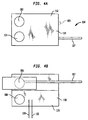
- Figures 4A and 4B illustrate a measurement cell useful for characterizing the electrical properties of a battery separator versus temperature.
- Cell 100 includes four 0.375 inch diameter nickel disks 102, 104, 106 and 108 all of which are 3 mils thick embedded in a Kapton® polyimide film, 110 , 112 which is also 3 mils thick.
- Figure 4A illustrates the top of the test cell, while Figure 4B illustrates the bottom of the test cell.
- the disks are fitted with nickel tabs indicated at 109 .
- Top assembly 114 and bottom assembly 116 are used to sandwich a separator by placing the separator there between and pressing the electrodes in a Carver press at a 125 psi with heated platens.
- the platens were heated at a constant rate from 60°C to 200°C using a Eurotherm® model 808 controller.
- the temperature of the electrode surface was sensed by two type E thermocouples indicated at 118 , 120 (0.5 mil thick, not shown) which were located between a pair of electrodes positioned adjacent to the electrodes holding the separator.
- Figure 5 shows typical electrical resistance curves versus temperature for commercially available battery separators measured as above at a heating rate or scan rate of 60°C per minute.
- Separator A is a polypropylene battery separator
- Separator B is a polyethylene battery separator
- Separator C is a polypropylene/polyethylene/polypropylene tri-layer separator. Separator C was also tested at a scan rate of 1° per minute and it was found that the high resistance exhibited above 130°C or so exhibited a slightly lower upper temperature limit.
- Figure 6 shows electrical properties of five different separators measured as described above at scan rates of 60°C per minute.
- Separators 6(a), 6(b), and 6(c) were polyethylene/polypropylene/polyethylene membranes prepared in accordance with Example 5.
- Separator D was a polypropylene/polyethylene/ polypropylene commercially available separator, while Separator E was a commercially available high molecular weight polyethylene separator.
Landscapes
- Engineering & Computer Science (AREA)
- Chemical & Material Sciences (AREA)
- Mechanical Engineering (AREA)
- Electrochemistry (AREA)
- General Chemical & Material Sciences (AREA)
- Chemical Kinetics & Catalysis (AREA)
- Thermal Sciences (AREA)
- Physics & Mathematics (AREA)
- Manufacturing & Machinery (AREA)
- Inorganic Chemistry (AREA)
- Cell Separators (AREA)
- Laminated Bodies (AREA)
- Extrusion Moulding Of Plastics Or The Like (AREA)
- Shaping By String And By Release Of Stress In Plastics And The Like (AREA)
- Secondary Cells (AREA)
Applications Claiming Priority (2)
| Application Number | Priority Date | Filing Date | Title |
|---|---|---|---|
| US09/296,682 US6346350B1 (en) | 1999-04-20 | 1999-04-20 | Structurally stable fusible battery separators and method of making same |
| US296682 | 1999-04-20 |
Publications (1)
| Publication Number | Publication Date |
|---|---|
| EP1047141A2 true EP1047141A2 (de) | 2000-10-25 |
Family
ID=23143080
Family Applications (1)
| Application Number | Title | Priority Date | Filing Date |
|---|---|---|---|
| EP20000108315 Withdrawn EP1047141A2 (de) | 1999-04-20 | 2000-04-15 | Formstabile schmelzbare Batterieseparatoren und Herstellungsverfahren |
Country Status (7)
| Country | Link |
|---|---|
| US (1) | US6346350B1 (de) |
| EP (1) | EP1047141A2 (de) |
| JP (1) | JP2000340207A (de) |
| KR (1) | KR20000071722A (de) |
| CN (1) | CN1271184A (de) |
| CA (1) | CA2301453A1 (de) |
| SG (1) | SG97881A1 (de) |
Cited By (8)
| Publication number | Priority date | Publication date | Assignee | Title |
|---|---|---|---|---|
| EP1348540A1 (de) * | 2002-03-27 | 2003-10-01 | Celgard Inc. | Mehrschichtige Batterieseparatoren |
| WO2006069307A3 (en) * | 2004-12-22 | 2006-08-17 | Entegris Inc | Multilayer porous membrane and process of manufacture |
| EP1930156A1 (de) * | 2005-09-28 | 2008-06-11 | Tonen Chemical Corporation | Verfahren zur herstellung einer mikroporösen polyethylenfolie und einer trennvorrichtung für eine zelle |
| WO2009132802A3 (de) * | 2008-05-02 | 2010-01-28 | Treofan Germany Gmbh & Co. Kg | Mikroporöse mehrschicht-membranfolie auf polypropylenbasis für batterien mit abschaltfunktion |
| WO2011086823A1 (en) * | 2010-01-13 | 2011-07-21 | Toray Tonen Specialty Separator Godo Kaisha | Microporous membranes and methods for producing and using such membranes |
| EP2089922A4 (de) * | 2006-11-17 | 2011-08-10 | Celgard Llc | Coextrudiertes mehrschichtiges batterietrennglied |
| US8551610B2 (en) | 2008-05-02 | 2013-10-08 | Treofan Germany Gmbh & Co. Kg | Single-layer polypropylene membrane film for batteries, having a shut-off function |
| US9067392B2 (en) | 2008-05-02 | 2015-06-30 | Treofan Germany Gmbh & Co. Kg | Membrane file for batteries, having a shut-off function |
Families Citing this family (24)
| Publication number | Priority date | Publication date | Assignee | Title |
|---|---|---|---|---|
| US6432586B1 (en) | 2000-04-10 | 2002-08-13 | Celgard Inc. | Separator for a high energy rechargeable lithium battery |
| US20050112462A1 (en) * | 2003-11-21 | 2005-05-26 | Marple Jack W. | High discharge capacity lithium battery |
| US8007940B2 (en) * | 2001-12-11 | 2011-08-30 | Eveready Battery Company, Inc. | High discharge capacity lithium battery |
| US6796554B2 (en) * | 2002-09-13 | 2004-09-28 | Hewlett-Packard Development Company, L.P. | Apparatus for stacking folded paper sheets |
| US7501008B2 (en) * | 2003-01-31 | 2009-03-10 | Microcell Corporation | Hydrogen storage systems and fuel cell systems with hydrogen storage capacity |
| US20050031943A1 (en) * | 2003-08-07 | 2005-02-10 | Call Ronald W. | Battery separator and method of making same |
| US8283071B2 (en) | 2003-11-21 | 2012-10-09 | Eveready Battery Company, Inc. | High discharge capacity lithium battery |
| US20050233214A1 (en) * | 2003-11-21 | 2005-10-20 | Marple Jack W | High discharge capacity lithium battery |
| US8124274B2 (en) * | 2003-11-21 | 2012-02-28 | Eveready Battery Company, Inc. | High discharge capacity lithium battery |
| US20050244717A1 (en) * | 2004-04-30 | 2005-11-03 | Celgard Inc. | Battery separator with antistatic properties |
| JP4291392B2 (ja) * | 2005-07-25 | 2009-07-08 | 帝人株式会社 | 非水系二次電池用セパレータ及びその製造方法 |
| US9492965B2 (en) * | 2005-10-19 | 2016-11-15 | Toray Battery Separator Film Co., Ltd | Method for producing multi-layer, microporous polyolefin membrane |
| PT103380B (pt) * | 2005-11-09 | 2007-09-13 | Univ Do Minho | Linha de extrusão laboratorial para a produção de filme tubular convencional e biorientado, com comutação simples entre as duas técnicas |
| CN101641406B (zh) * | 2007-01-19 | 2012-12-26 | 东丽电池隔膜株式会社 | 聚合材料和它的制备和使用 |
| JP4801705B2 (ja) * | 2008-09-03 | 2011-10-26 | 三菱樹脂株式会社 | セパレータ用積層多孔性フィルム、およびその製造方法 |
| JP5519682B2 (ja) * | 2008-10-24 | 2014-06-11 | 東レバッテリーセパレータフィルム株式会社 | 多層微多孔膜ならびにかかる膜を製造および使用するための方法 |
| CN102820444B (zh) * | 2011-06-10 | 2015-09-30 | 比亚迪股份有限公司 | 一种电池隔膜及其制备方法 |
| KR101295525B1 (ko) * | 2011-06-17 | 2013-08-12 | (주)이쎌텍 | 전지의 분리막용 미세다공성 필름 제조 장치 및 그 장치를 이용한 필름 제조방법 |
| JP5883379B2 (ja) * | 2011-09-08 | 2016-03-15 | 日新製鋼株式会社 | 電池外装用積層体およびその製造方法ならびに二次電池 |
| CN103035864B (zh) * | 2011-09-30 | 2017-06-06 | 天津东皋膜技术有限公司 | 具有压缩弹性热关断耐高温的涂层隔膜 |
| CN102700222B (zh) * | 2012-05-02 | 2015-07-01 | 达尼特材料科技(芜湖)有限公司 | 多孔膜及其制造方法 |
| CN103128975B (zh) * | 2012-12-28 | 2014-10-15 | 深圳中兴创新材料技术有限公司 | 一种聚丙烯微孔膜的制备方法、聚丙烯微孔膜及其应用 |
| CN114649642A (zh) * | 2015-07-31 | 2022-06-21 | 赛尔格有限责任公司 | 干法工艺膜、电池隔板以及锂离子电池 |
| JP7156942B2 (ja) * | 2015-09-18 | 2022-10-19 | セルガード エルエルシー | 改良された膜、カレンダー加工された微多孔膜、電池セパレータ、および関連する方法 |
Family Cites Families (27)
| Publication number | Priority date | Publication date | Assignee | Title |
|---|---|---|---|---|
| US3679538A (en) * | 1970-10-28 | 1972-07-25 | Celanese Corp | Novel open-celled microporous film |
| CA1028440A (en) * | 1973-02-26 | 1978-03-21 | Uop Inc. | Polymer compositions with treated filler |
| EP0099228A3 (de) * | 1982-07-06 | 1985-05-15 | Exxon Research And Engineering Company | Elektroempfindliche Übertragungsschicht |
| US4539256A (en) * | 1982-09-09 | 1985-09-03 | Minnesota Mining And Manufacturing Co. | Microporous sheet material, method of making and articles made therewith |
| US4436888A (en) * | 1982-10-05 | 1984-03-13 | E. I. Du Pont De Nemours And Company | Method for making balanced low shrink tension polyolefin film |
| US4634739A (en) * | 1984-12-27 | 1987-01-06 | E. I. Du Pont De Nemours And Company | Blend of polyethylene and polypropylene |
| US4650730A (en) | 1985-05-16 | 1987-03-17 | W. R. Grace & Co. | Battery separator |
| US4882466A (en) * | 1988-05-03 | 1989-11-21 | Raychem Corporation | Electrical devices comprising conductive polymers |
| JP2642206B2 (ja) | 1989-12-28 | 1997-08-20 | 旭化成工業株式会社 | 防爆型二次電池 |
| US5851610A (en) * | 1991-02-07 | 1998-12-22 | Applied Extrusion Technologies, Inc. | Shrink films and articles including the same |
| JPH0698395A (ja) | 1991-09-30 | 1994-04-08 | Iwatsu Electric Co Ltd | 音源用振動板 |
| US5240655A (en) | 1991-12-20 | 1993-08-31 | W. R. Grace & Co.-Conn. | Process of making a battery separator |
| US5281491A (en) | 1991-12-20 | 1994-01-25 | W. R. Grace & Co. | Battery separator |
| JPH0698394A (ja) | 1992-09-11 | 1994-04-08 | Pioneer Cone Corp | スピーカ用振動部品の製造方法 |
| JP3352801B2 (ja) | 1994-01-31 | 2002-12-03 | 日東電工株式会社 | 多孔質フィルム、その製造法およびその用途 |
| US5667911A (en) * | 1994-11-17 | 1997-09-16 | Hoechst Celanese Corporation | Methods of making cross-ply microporous membrane battery separator, and the battery separators made thereby |
| US5565281A (en) | 1994-12-02 | 1996-10-15 | Hoechst Celanese Corporation | Shutdown, bilayer battery separator |
| TW297171B (de) * | 1994-12-20 | 1997-02-01 | Hoechst Celanese Corp | |
| JPH08244152A (ja) * | 1995-03-15 | 1996-09-24 | Nitto Denko Corp | 多孔質フィルムおよびその製造法 |
| JPH08250097A (ja) | 1995-03-15 | 1996-09-27 | Kureha Chem Ind Co Ltd | 電気化学的装置用極間セパレーター |
| JPH08266398A (ja) | 1995-03-30 | 1996-10-15 | Nippon Sanso Kk | 断熱調理鍋 |
| JP3508295B2 (ja) | 1995-04-24 | 2004-03-22 | カシオ計算機株式会社 | 薄膜トランジスタの製造方法 |
| JP3203160B2 (ja) | 1995-08-09 | 2001-08-27 | 三菱電機株式会社 | ボリューム・レンダリング装置及び方法 |
| JP3939778B2 (ja) | 1996-02-09 | 2007-07-04 | 日東電工株式会社 | 電池用セパレータ |
| JPH10154499A (ja) * | 1996-11-22 | 1998-06-09 | Nitto Denko Corp | 電池用セパレータ及びこれを用いた非水系2次電池 |
| US5993954A (en) * | 1997-04-29 | 1999-11-30 | 3M Innovative Properties Company | Temperature-sensitive microporous film |
| US5888640A (en) * | 1997-07-09 | 1999-03-30 | Mobil Oil Corporation | Metallized uniaxially shrinkable biaxially oriented polypropylene film |
-
1999
- 1999-04-20 US US09/296,682 patent/US6346350B1/en not_active Expired - Lifetime
-
2000
- 2000-03-21 CA CA002301453A patent/CA2301453A1/en not_active Abandoned
- 2000-04-04 SG SG200001906A patent/SG97881A1/en unknown
- 2000-04-15 EP EP20000108315 patent/EP1047141A2/de not_active Withdrawn
- 2000-04-18 KR KR1020000020321A patent/KR20000071722A/ko not_active Application Discontinuation
- 2000-04-19 CN CN00106839A patent/CN1271184A/zh active Pending
- 2000-04-20 JP JP2000119291A patent/JP2000340207A/ja active Pending
Cited By (17)
| Publication number | Priority date | Publication date | Assignee | Title |
|---|---|---|---|---|
| CN1300862C (zh) * | 2002-03-27 | 2007-02-14 | 思凯德公司 | 多层电池隔板 |
| EP1348540A1 (de) * | 2002-03-27 | 2003-10-01 | Celgard Inc. | Mehrschichtige Batterieseparatoren |
| WO2006069307A3 (en) * | 2004-12-22 | 2006-08-17 | Entegris Inc | Multilayer porous membrane and process of manufacture |
| US8758887B2 (en) | 2004-12-22 | 2014-06-24 | Entegris, Inc. | Multilayer porous membrane and process |
| EP1930156A4 (de) * | 2005-09-28 | 2011-11-23 | Toray Tonen Specialty Separato | Verfahren zur herstellung einer mikroporösen polyethylenfolie und einer trennvorrichtung für eine zelle |
| EP1930156A1 (de) * | 2005-09-28 | 2008-06-11 | Tonen Chemical Corporation | Verfahren zur herstellung einer mikroporösen polyethylenfolie und einer trennvorrichtung für eine zelle |
| EP2089922A4 (de) * | 2006-11-17 | 2011-08-10 | Celgard Llc | Coextrudiertes mehrschichtiges batterietrennglied |
| US10818899B2 (en) | 2006-11-17 | 2020-10-27 | Celgard, Llc | Co-extruded, multi-layered battery separator |
| US10003058B2 (en) | 2006-11-17 | 2018-06-19 | Celgard, Llc | Method of making a co-extruded, multi-layered battery separator |
| US9067392B2 (en) | 2008-05-02 | 2015-06-30 | Treofan Germany Gmbh & Co. Kg | Membrane file for batteries, having a shut-off function |
| US8551610B2 (en) | 2008-05-02 | 2013-10-08 | Treofan Germany Gmbh & Co. Kg | Single-layer polypropylene membrane film for batteries, having a shut-off function |
| WO2009132802A3 (de) * | 2008-05-02 | 2010-01-28 | Treofan Germany Gmbh & Co. Kg | Mikroporöse mehrschicht-membranfolie auf polypropylenbasis für batterien mit abschaltfunktion |
| US8906540B2 (en) | 2008-05-02 | 2014-12-09 | Treofan Germany Gmbh & Co. Kg | Micro-porous multi-layer membrane film based on polypropylene for batteries with a cut-off function |
| CN102740956A (zh) * | 2010-01-13 | 2012-10-17 | 东丽电池隔膜合同会社 | 微孔性膜和用于制备和使用这样的膜的方法 |
| CN102740956B (zh) * | 2010-01-13 | 2015-11-25 | 东丽电池隔膜株式会社 | 微孔性膜和用于制备和使用这样的膜的方法 |
| US9044716B2 (en) | 2010-01-13 | 2015-06-02 | Toray Battery Separator Film Co., Ltd. | Microporous membranes and methods for producing and using such membranes |
| WO2011086823A1 (en) * | 2010-01-13 | 2011-07-21 | Toray Tonen Specialty Separator Godo Kaisha | Microporous membranes and methods for producing and using such membranes |
Also Published As
| Publication number | Publication date |
|---|---|
| US6346350B1 (en) | 2002-02-12 |
| SG97881A1 (en) | 2003-08-20 |
| CA2301453A1 (en) | 2000-10-20 |
| KR20000071722A (ko) | 2000-11-25 |
| JP2000340207A (ja) | 2000-12-08 |
| CN1271184A (zh) | 2000-10-25 |
Similar Documents
| Publication | Publication Date | Title |
|---|---|---|
| US6346350B1 (en) | Structurally stable fusible battery separators and method of making same | |
| KR100699120B1 (ko) | 감소된 분열 성향을 지닌 배터리 격리판 | |
| TWI425045B (zh) | 多層微多孔聚烯烴膜、其製法、及由它製得之電池隔離材 | |
| KR100554637B1 (ko) | 다중층 전지 격리판 | |
| KR100512540B1 (ko) | 삼층 배터리 분리기의 제조 방법 | |
| TWI413657B (zh) | 聚烯烴多層微多孔膜、其製法、電池用隔離材及電池 | |
| CN110815763B (zh) | 制备高强度高模量的聚烯烃薄膜的设备及方法和高强度高模量的聚烯烃薄膜 | |
| KR102266028B1 (ko) | 폴리올레핀 미다공막 및 이의 제조 방법 | |
| EP2660277A1 (de) | Poröse polyolefinmembran und verfahren zu ihrer herstellung | |
| EP0718901A1 (de) | Dreilagiger, mikroporöser Batterieseparator | |
| JP4516796B2 (ja) | 電池セパレータおよびその製造方法 | |
| KR101404451B1 (ko) | 다층 폴리올레핀계 미세다공막 및 그 제조방법 | |
| EP0715364A1 (de) | Zweilagiger Batterieseparator mit Shutdown-Charakteristik | |
| JP7047382B2 (ja) | ポリオレフィン微多孔膜、リチウムイオン二次電池及びポリオレフィン微多孔膜製造方法 | |
| JPWO2018043335A1 (ja) | 微多孔膜、リチウムイオン二次電池及び微多孔膜製造方法 | |
| KR101452945B1 (ko) | 다층 폴리올레핀계 미세다공막 및 그 제조방법 | |
| EP0924780B1 (de) | Fünflagiger Batterieseparator | |
| JPH05214140A (ja) | ポリテトラフルオロエチレン製多孔質膜およびその製造方法 | |
| CN118648179A (zh) | 多层隔膜的制备方法 | |
| WO2009035167A2 (en) | Extrusion die having cantilevered die lip adjustment system and a flow manifold and method of extrusion |
Legal Events
| Date | Code | Title | Description |
|---|---|---|---|
| PUAI | Public reference made under article 153(3) epc to a published international application that has entered the european phase |
Free format text: ORIGINAL CODE: 0009012 |
|
| AK | Designated contracting states |
Kind code of ref document: A2 Designated state(s): AT BE CH CY DE DK ES FI FR GB GR IE IT LI LU MC NL PT SE |
|
| AX | Request for extension of the european patent |
Free format text: AL;LT;LV;MK;RO;SI |
|
| STAA | Information on the status of an ep patent application or granted ep patent |
Free format text: STATUS: THE APPLICATION HAS BEEN WITHDRAWN |
|
| 18W | Application withdrawn |
Effective date: 20060216 |