EP1046500A1 - Kühl- und Befeuchtungseinheit für Rotationsdruckmaschinen - Google Patents
Kühl- und Befeuchtungseinheit für Rotationsdruckmaschinen Download PDFInfo
- Publication number
- EP1046500A1 EP1046500A1 EP00106010A EP00106010A EP1046500A1 EP 1046500 A1 EP1046500 A1 EP 1046500A1 EP 00106010 A EP00106010 A EP 00106010A EP 00106010 A EP00106010 A EP 00106010A EP 1046500 A1 EP1046500 A1 EP 1046500A1
- Authority
- EP
- European Patent Office
- Prior art keywords
- cooling
- conditioning unit
- rollers
- material web
- housing
- Prior art date
- Legal status (The legal status is an assumption and is not a legal conclusion. Google has not performed a legal analysis and makes no representation as to the accuracy of the status listed.)
- Granted
Links
- 238000001816 cooling Methods 0.000 title claims abstract description 126
- 230000003750 conditioning effect Effects 0.000 claims abstract description 53
- 239000000463 material Substances 0.000 claims description 61
- 238000007639 printing Methods 0.000 claims description 19
- 239000007788 liquid Substances 0.000 claims description 14
- 238000001035 drying Methods 0.000 claims description 3
- 238000011144 upstream manufacturing Methods 0.000 claims description 2
- 239000003973 paint Substances 0.000 claims 1
- 239000000975 dye Substances 0.000 abstract 1
- 239000004744 fabric Substances 0.000 abstract 1
- 241001131696 Eurystomus Species 0.000 description 24
- 239000012530 fluid Substances 0.000 description 3
- 238000000034 method Methods 0.000 description 3
- 229920001296 polysiloxane Polymers 0.000 description 3
- 239000000758 substrate Substances 0.000 description 3
- 238000009833 condensation Methods 0.000 description 2
- 230000005494 condensation Effects 0.000 description 2
- 238000010276 construction Methods 0.000 description 2
- 238000001704 evaporation Methods 0.000 description 2
- 239000002904 solvent Substances 0.000 description 2
- 239000002826 coolant Substances 0.000 description 1
- 230000000694 effects Effects 0.000 description 1
- 230000008030 elimination Effects 0.000 description 1
- 238000003379 elimination reaction Methods 0.000 description 1
- 239000010408 film Substances 0.000 description 1
- 238000009499 grossing Methods 0.000 description 1
- 238000010438 heat treatment Methods 0.000 description 1
- 238000007645 offset printing Methods 0.000 description 1
- 230000037361 pathway Effects 0.000 description 1
- 230000029058 respiratory gaseous exchange Effects 0.000 description 1
- 239000010409 thin film Substances 0.000 description 1
- 230000007704 transition Effects 0.000 description 1
Images
Classifications
-
- B—PERFORMING OPERATIONS; TRANSPORTING
- B41—PRINTING; LINING MACHINES; TYPEWRITERS; STAMPS
- B41F—PRINTING MACHINES OR PRESSES
- B41F23/00—Devices for treating the surfaces of sheets, webs, or other articles in connection with printing
- B41F23/04—Devices for treating the surfaces of sheets, webs, or other articles in connection with printing by heat drying, by cooling, by applying powders
- B41F23/0476—Cooling
- B41F23/0479—Cooling using chill rolls
-
- B—PERFORMING OPERATIONS; TRANSPORTING
- B41—PRINTING; LINING MACHINES; TYPEWRITERS; STAMPS
- B41F—PRINTING MACHINES OR PRESSES
- B41F23/00—Devices for treating the surfaces of sheets, webs, or other articles in connection with printing
- B41F23/02—Devices for treating the surfaces of sheets, webs, or other articles in connection with printing by dampening
Definitions
- the present invention relates to a cooling and humidifying unit for Rotary printing machines, in particular for rotary printing machines for processing of material webs.
- An apparatus for dissipating heat from a web includes one Cooling roll with a cylindrical surface.
- the web is moving along one Path that extends partially around the chill roll. Between the two side parts the web extends around part of the cylindrical outer surface of the cooling roll in Circumferential direction a nozzle.
- An air flow is counteracted through the middle part of the nozzle directed a middle part of the web and above a point where the web normally comes into contact with the chill roller around the middle part of the web bend and bring it into contact with the chill roll in this way.
- Lateral nozzle parts extend on both sides of the middle part of the nozzle, namely below the point where the middle part of the web is towards the chill roll is bent. This creates a smoothing in the transverse direction and along the middle Part of the track achieved.
- the present invention relates to the cooling of a printed or coated material web, which in particular according to the offset printing process was printed and consists of paper.
- the material web has after applying Color passes through a heating zone and is passed over a variety of cooling rolls Cooling roll stand led.
- the flow of the cooling medium through the cooling rollers a cooling roll stand by two different cooling circuits different Temperature levels generated and against the direction of travel of a material web over the Cooling rollers directed.
- the cooling rolls are more conventional Wise arranged quite a lot of construction and floor space and only two of the Cooling rollers are arranged one above the other.
- EP 0 627 311 B1 relates to a web cooling device.
- the device according to This publication allows cooling one in a dryer Web printing machine heated printing material web with a downstream of the dryer and the support roller or turning device guiding the printing material web.
- a second downstream of the support roller or turning device and the printing material web leading roller with a first liquid application roller for applying liquid on a first side of the printing material web and a second liquid application roller to apply liquid to a second side of the substrate.
- the Liquid application rollers are on opposite sides of the Printing material web between the support roller or the turning device and the second Roller arranged.
- the liquid application rollers are together one between the support roller or turning device and the second roller assigned to the printing substrate web section and offset from one another. They create a pressure contact along a contact area on the printing material web in the Way that the substrates can be wetted.
- the invention has for its object to significantly shorten the length of a cooling and conditioning unit and at the same time reduce the Increase cooling effectiveness.
- Another object of the present invention is that in one Print shop necessary footprint for such Correct the cooling and conditioning unit considerably. After all, with the solution according to the invention a lateral run of the material web during the passage the cooling and conditioning unit can be prevented.
- the cooling rollers may be arranged offset from one another around the material web passing through them to impress an essentially arched path and high Realize wrap angle.
- the cooling rolls according to the present invention can be arranged offset from each other, both offset in height as also offset with respect to the length of the housing. Due to the staggered arrangement and applying a substantially arcuate web path high wrap angles can be achieved on the chill rolls, resulting in a particularly effective heat transfer.
- the cooling and conditioning unit according to the invention present invention comprise a conditioning unit for applying a liquid for example moisture or silicone on one or both sides of the Conditioning unit passing material web.
- the conditioning rollers of the Conditioning plant can be arranged opposite each other and either a common liquid container or a shared liquid container have to maintain a constant fluid supply to the aforementioned surfaces enable.
- Cooling rolls have a relatively small diameter in relation to their width, i. e. between 100 mm and 250 mm, preferably about 250 mm in diameter.
- the relatively small one Diameter of the cooling rolls according to the invention allows a high one to be maintained Traction levels between the web and the surfaces of the chill rolls, with little Air is trapped between the roll surface and the web. This in turn favors the heat transfer coefficient and enables the elimination of the Corrugation of the web across the web width during the passage of the cooling rolls in Web direction.
- the arrangement of the cooling rolls according to the invention one above the other within the housing uses its height very effectively, compared to that of the prior art known housings. Exploiting the height of such instead of its length allows a short overall length and therefore little floor space in the printing shop.
- the cooling and conditioning unit according to the invention is relatively close to the following one Turning bar superstructure is only a small free path for the Post-evaporation of solvents is possible, which means additional post-evaporation restricted, so that the operating personnel no additional solvent pollution of the Breathing air is exposed.
- the cooling and conditioning unit according to the invention can be one Dryer of a rotary printing machine for both commercial and colored printing Newspaper printing must be assigned.
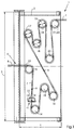
- the cooling and conditioning unit 1 is immediate arranged behind the outlet of a dryer.
- the dryer contains a corresponding one upper dryer zone and a corresponding lower dryer zone, between which there is extends a web running level.
- the cooling and conditioning unit 1 comprises a first one Cooling roller 8 with a diameter 24.
- the web 7 of either one or both sides are printed, is deflected by the first cooling roller 8 by 90 ° and follows a downwardly extending web path, which the web 7 in Web running direction 9 leads.
- a conditioning unit which is used for the application moisture or other fluid such as silicone on one or both Surfaces of the material web 7 allowed.
- the conditioning unit 11 closes two Conditioning rollers 12, which are arranged opposite one another.
- Each of the Conditioning rollers 12 are immersed in and conveyed from a liquid container apply a thin film of liquid to the material web.
- the material web 7 becomes a downward trajectory embossed, within the downward trajectory it is provided with said liquid film, with no web deflection between the first cooling roller 8 and a cooling roller 14 arranged further downstream is coming. It is only through the cooling roller 14 that the further web path 12 becomes one again diverted upward extending path portion, d. H. the material web 7 experiences one Redirection by about 180 °.
- the material web On a further cooling roller 15, the material web is rotated through an angle of approximately 180 ° distracted. On a further cooling roller 16, the material web 7 is turned through an angle deflected more than 180 °, but less than 270 °, the material web 7 of this pair of Cooling rollers leave in an inclined direction, with the web path slightly upward is pointing.
- a further pair of cooling rolls consisting of the cooling rolls 17, 18, which are arranged in approximately the same configuration as the two previous ones described cooling rollers 15, 16.
- the material web 7 runs on the first cooling roller 17 of the said further pair of cooling rollers starting from their inclined path on, the material web 7 the surface of this cooling roller 17 further Cooling roller pairs wrapped at an angle between 180 ° and 270 °. After that the material web 7 the surface of the first cooling roll 17 further Cooling roller pair 17, 18 has passed, it runs in an inclined A web path section that is between the second cooling roller 18 of said Cooling roller pair and a cooling roller 19 extends.
- the material web 7 is during the Passage of the cooling rollers 20, 21 deflected in the manner shown. After the Material web 7 has left the surface of the second cooling roller 21, the runs Material web 7 in the cooling and conditioning unit 1 in the horizontal direction.
- the cooling rollers 8, 14, 15, 16, 17, 18, 19, 20 and 21 all in a staggered configuration with respect to one another arranged, the first cooling roller 8 closer to the inlet of the material web in the housing 2 7 is arranged in the cooling and conditioning unit 1 compared to the cooling rollers 15 and 16.
- the height 3 of the housing 2 can accommodate the plurality of Cooling rollers 8, 14, 15, 16, 17, 18, 19, 20 and 21 can be used. Because the web of material the cooling and conditioning unit 1 according to the present invention in close proximity leaves for a subordinate turning bar superstructure, it is only for a very short one Exposed to the environment, resulting in only a minimal boundary layer build-up on both Sides of the freely moving web of material is possible.
- the material web essentially leaves the cooling and conditioning unit 1 horizontal direction to enter a turning bar superstructure, the one Longitudinal folding section of a folder or a longitudinal cutting section of a Turning bar superstructure is upstream to a variety of train strands from the To produce material web 7.
- a high degree of web tension exerted on the material web enables a relatively close contact between the material web surface 7 and the surface of a corresponding cooling roller which is just passing the material web 7. This improves the conditions for optimal heat transfer. Additional web tension rollers or air nozzles can be avoided by high web tensions obtained in this way within the material web 7. Since the cooling rollers according to the present invention are optimized with regard to a certain inertia, they can only be driven within the cooling and conditioning unit 1 due to friction, so that an additional drive can be deployed. However, it is optionally possible to drive one or a plurality of the cooling rolls according to the invention within the cooling and conditioning unit 1 with a separate drive motor.
- Another advantage of the invention is thanks to the immediate transition from Material web 7 from the dryer outlet into the cooling and conditioning unit inlet 6
- This allows boundary layers to build up on the surfaces of the material web 7 be eliminated.
- the boundary layers adhering to the surfaces of the material web 7 have the disadvantageous effect that they have an air cushion between the surface of the first Form cooling roller 8, which is located closest to dryer outlet 6.
- the Air cushions in turn result in disadvantageous oil condensation on their surface, which represents a detachment of the ink on the first cooling roller and one Retransfer of ink deposited on the surface of the first cooling roller already printed side of the material web results.
- the small diameter 24 of the Chill rolls also allow a relatively high web tension to be maintained for close contact between the web and the heat-exchanging surfaces.
- the material web 7 passes through the cooling and Conditioning unit 1, the material web 7 having a plurality of cooling rolls only small diameter 24 happens.
- the diameter of the cooling rolls is relatively small in terms of their width. Since the plurality of cooling rolls 8, 14, 15, 16, 17, 18, 19, 20 and 21 are arranged in a staggered configuration with respect to one another within the housing 2 a plurality of cooling rollers can also be used in the housing 2 whose overall height 3 can be accommodated.
Landscapes
- Engineering & Computer Science (AREA)
- Mechanical Engineering (AREA)
- Supply, Installation And Extraction Of Printed Sheets Or Plates (AREA)
- Treatment Of Fiber Materials (AREA)
- Drying Of Solid Materials (AREA)
- Motor Or Generator Cooling System (AREA)
Abstract
Description
- 1
- Kühl- und Konditioniereinheit
- 2
- Gehäuse
- 3
- Höhe
- 4
- Länge
- 5
- Bahnlaufpfad
- 6
- Kühl- und Konditioniereinheitseintritt
- 7
- Bahn
- 8
- erste Kühlwalze
- 9
- Bahnlaufrichtung
- 10
- Bahneinzugsvorrichtung
- 11
- Konditionierwerk
- 12
- Konditionierwalze
- 13
- Kasten
- 14
- Kühlwalze
- 15
- Kühlwalze
- 16
- Kühlwalze
- 17
- Kühlwalze
- 18
- Kühlwalze
- 19
- Kühlwalze
- 20
- Kühlwalze
- 21
- Kühlwalze
- 22
- Auslaufbereich
- 23
- Auslaufwalze
- 24
- Durchmesser
Claims (14)
- Kühl- und Konditionereinheit (1) für eine Materialbahn, auf die an wenigstens einer Seite Farbe aufgetragen ist, mit einer Vielzahl von Kühlwalzen (8, 14, 15, 16, 17, 18, 19, 20, 21), die in einem Gehäuse (2) im wesentlichen vertikal übereinander unter Ausnutzung der Höhe (3) des Gehäuses (2) angeordnet sind, und um welche die Materialbahn (7) entlang eines sich im wesentlichen vertikal erstreckenden Bahnpfades geführt ist, und wobei der Kühl- und Konditioniereinheit (1) ein Trockner zum Trocknen der Materialbahn (7) vorgeordnet ist,
dadurch gekennzeichnet,
daß die Kühl- und Konditioniereinheit (1) dem Trockner unmittelbar nachgeordnet ist, in der Weise, daß die Materialbahn (7) vom Trocknerausgang unmittelbar in den Eingang (6) der Kühl- und Konditioniereinheit (1) eintritt. - Kühl- und Konditioniereinheit gemäß Anspruch 1,
dadurch gekennzeichnet,
daß das Gehäuse (2) der Kühl- und Konditioniereinheit (1) unmittelbar an das Gehäuse des vorgeordneten Trockners angrenzt. - Kühl- und Konditioniereinheit gemäß Anspruch 1,
dadurch gekennzeichnet,
daß das Gehäuse (2) der Kühl- und Konditioniereinheit (1) in das Gehäuse des Trockners integriert ist. - Kühl- und Konditioniereinheit gemäß einem der vorhergehenden Ansprüche,
dadurch gekennzeichnet,
daß die Kühlwalzen (8, 14, 15, 16, 17, 18, 19, 20, 21) versetzt zueinander angeordnet sind. - Kühl- und Konditioniereinheit gemäß Anspruch 4,
dadurch gekennzeichnet,
daß die Kühlwalzen (8, 14, 15, 16, 17, 18, 19, 20, 21) in bezug auf die Höhe (3) des Gehäuses (2) versetzt zueinander angeordnet sind. - Kühl- und Konditiniereinheit gemäß Anspruch 4 oder 5,
dadurch gekennzeichnet,
daß die Kühlwalzen (8, 14, 15, 16, 17, 18, 19, 20, 21) in bezug auf die Länge (4) des Gehäuses (2) versetzt zueinander angeordnet sind. - Kühl- und Konditioniereinheit gemäß einem der vorhergehenden Ansprüche,
dadurch gekennzeichnet,
daß die Kühlwalzen in einer im wesentlichen vertikal verlaufenden Ebene paarweise übereinanderliegend angeordnet sind. - Kühl- und Konditioniereinheit gemäß einem der vorhergehenden Ansprüche,
dadurch gekennzeichnet,
daß diese zwei einander gegenüberliegend angeordnete Konditionierwalzen (12) zum Auftrag eines Flüssigkeitsfilmes auf die Materialbahn (7) umfaßt. - Kühl- und Konditioniereinheit gemäß Anspruch 8,
dadurch gekennzeichnet,
daß die Konditionierwalzen (12) in Laufrichtung der Materialbahn gesehen zwischen der ersten Kühlwalze (8) und weiteren Kühlwalzen (14 - 21) angeordnet sind. - Kühl- und Konditioniereinheit gemäß einem der vorhergehenden Ansprüche,
dadurch gekennzeichnet,
daß der Durchmesser (24) der Kühlwalzen (8, 14 - 21) kleiner als 300 mm ist. - Kühl- und Konditioniereinheit nach einem der vorhergehenden Ansprüche,
dadurch gekennzeichnet,
daß zumindest ein Teil der Kühlwalzen (8, 14 - 21) motorisch angetriebene Walzen sind. - Kühl- und Konditioniereinheit nach einem der Ansprüche 1 bis 10,
dadurch gekennzeichnet,
daß zumindest ein Teil der Kühlwalzen (8, 14 -21) frei drehbare, nicht angetriebene Walzen sind. - Trockner zum Trocknen einer bedruckten Materialbahn (7) in einer Rollenrotationsdruckmaschine,
gekennzeichnet durch
eine Vielzahl von Kühlwalzen (8, 14 - 21), die im Gehäuse (2) des Trockners im wesentlichen vertikal übereinander unter Ausnutzung der Höhe (3) des Gehäuses in der Weise angeordnet sind, daß die Materialbahn (7) entlang eines sich im wesentlichen vertikal erstreckenden Bahnpfades um die Kühlwalzen (8, 14 - 21) geführt ist. - Trockner gemäß Anspruch 13,
dadurch gekennzeichnet,
daß dieser zwei einander gegenüberliegend angeordnete Konditionierwalzen (12) zum Auftrag eines Flüssigkeitsfilmes auf die Materialbahn (7) umfaßt.
Applications Claiming Priority (2)
| Application Number | Priority Date | Filing Date | Title |
|---|---|---|---|
| DE19918130 | 1999-04-21 | ||
| DE19918130A DE19918130A1 (de) | 1999-04-21 | 1999-04-21 | Kühl- und Befeuchtungseinheit für Rotationsdruckmaschinen |
Publications (2)
| Publication Number | Publication Date |
|---|---|
| EP1046500A1 true EP1046500A1 (de) | 2000-10-25 |
| EP1046500B1 EP1046500B1 (de) | 2002-08-28 |
Family
ID=7905386
Family Applications (1)
| Application Number | Title | Priority Date | Filing Date |
|---|---|---|---|
| EP00106010A Expired - Lifetime EP1046500B1 (de) | 1999-04-21 | 2000-03-27 | Kühl- und Befeuchtungseinheit für Rotationsdruckmaschinen |
Country Status (5)
| Country | Link |
|---|---|
| US (1) | US6318263B1 (de) |
| EP (1) | EP1046500B1 (de) |
| JP (1) | JP2000351198A (de) |
| AT (1) | ATE222854T1 (de) |
| DE (2) | DE19918130A1 (de) |
Cited By (3)
| Publication number | Priority date | Publication date | Assignee | Title |
|---|---|---|---|---|
| DE20207526U1 (de) | 2002-05-14 | 2002-08-29 | Vits Maschinenbau GmbH, 40764 Langenfeld | Vorrichtung zum Kühlen und Konditionieren einer Bahn |
| WO2007135213A1 (es) | 2006-05-22 | 2007-11-29 | Digital Internet Transport System, S.L. | Procedimiento y dispositivo para acondicionamiento de papel |
| CN109878206A (zh) * | 2019-03-06 | 2019-06-14 | 南安市星盛工业设计有限公司 | 用于床上纺织用品加工的印花设备 |
Families Citing this family (15)
| Publication number | Priority date | Publication date | Assignee | Title |
|---|---|---|---|---|
| DE19918669A1 (de) * | 1999-04-23 | 2000-10-26 | Heidelberger Druckmasch Ag | Trockner mit integrierter Kühleinheit |
| US6299685B1 (en) * | 2000-02-11 | 2001-10-09 | Hurletron, Incorporated | Web processing with electrostatic moistening |
| DE10123489B4 (de) * | 2001-05-15 | 2009-04-02 | Goss Contiweb B.V. | Vorrichtung zum Kühlen einer Materialbahn |
| DE10231598A1 (de) * | 2001-08-07 | 2003-02-20 | Heidelberger Druckmasch Ag | Vorrichtung zum Wiederbefeuchten einer Warenbahn |
| US20040045996A1 (en) * | 2002-09-06 | 2004-03-11 | Lamothe Richard P. | Web outfeed processing system for high performance printer |
| DE102004002232B4 (de) * | 2004-01-15 | 2007-09-13 | OCé PRINTING SYSTEMS GMBH | Multifunktionseinrichtung zur Nachbearbeitung einer von einer elektrografischen Druckeinrichtung bedruckten Bedruckstoffbahn |
| DE102004002234B4 (de) * | 2004-01-15 | 2007-06-21 | OCé PRINTING SYSTEMS GMBH | Einrichtung zur Regulierung der Gleiteigenschaften eines Bedruckstoffes bei einer elektrografischen Druck- oder Kopiereinrichtung |
| ITBO20040357A1 (it) * | 2004-06-04 | 2004-09-04 | Gd Spa | Unita' di stampa in una macchina confezionatrice dia rticoli da fumo |
| DE102006027147B4 (de) * | 2006-06-12 | 2011-05-12 | Koenig & Bauer Aktiengesellschaft | Kühlwalzenständer zur Kühlung einer hindurchgeführten Materialbahn |
| EP1795347A3 (de) | 2005-10-28 | 2010-10-27 | Koenig & Bauer Aktiengesellschaft | Kühlwalzenständer und ein Verfahren zur Kühlung einer hindurchgeführten Materialbahn |
| US20080046389A1 (en) * | 2006-08-17 | 2008-02-21 | Kimberly-Clark Worldwide, Inc. | Method of marketing a product |
| AU2008230080B2 (en) | 2007-03-23 | 2012-04-26 | Megtec Systems, Inc. | Web coating applicator with cooling and material recovery |
| JP2012045788A (ja) * | 2010-08-25 | 2012-03-08 | Fujifilm Corp | 画像記録装置 |
| CN106052347A (zh) * | 2016-07-07 | 2016-10-26 | 无锡市昂益达机械有限公司 | 一种印染烘燥装置 |
| CN114322518B (zh) * | 2022-03-11 | 2022-07-15 | 潍坊富群新材料有限公司 | 一种防水卷材生产用胎基布烘干装置 |
Citations (10)
| Publication number | Priority date | Publication date | Assignee | Title |
|---|---|---|---|---|
| US3198199A (en) * | 1964-02-10 | 1965-08-03 | Herman J Schultz | Apparatus for dampening a printed web |
| US3647525A (en) * | 1959-10-05 | 1972-03-07 | Dahlgren Mfg Co | Method and means for applying liquid to a moving web |
| DE2947785A1 (de) * | 1979-11-28 | 1981-06-04 | Großdruckerei G.H. Fix GmbH, 6740 Landau | Verfahren und vorrichtung zum trocknen von auf ein bahnfoermiges traegermaterial aufgetragenen druckfarben |
| EP0130625A2 (de) * | 1983-07-05 | 1985-01-09 | Franz Böhnensieker | Verfahren und Vorrichtung zum Wärmetrocknen insbesondere bedruckter oder gefärbter Bahnen |
| EP0396173A1 (de) * | 1989-04-26 | 1990-11-07 | Stork Contiweb B.V. | Vorrichtung zum Abkühlen einer aus einem Trockner kommenden Materialbahn |
| WO1994004364A1 (de) * | 1992-08-17 | 1994-03-03 | Weitmann & Konrad Gmbh & Co. Kg | Verfahren und vorrichtung zum befeuchten einer bedruckten und anschliessend thermsich getrockneten, bewegten materialbahn |
| EP0699529A1 (de) * | 1994-09-02 | 1996-03-06 | V.I.B. Apparatebau GmbH | Verfahren und Vorrichtung zum Bedrucken einer Materialbahn |
| JPH09174815A (ja) * | 1995-12-25 | 1997-07-08 | Toppan Printing Co Ltd | オフセット輪転印刷機及びそのインキ固着方法 |
| EP0627311B1 (de) * | 1993-04-30 | 1998-07-15 | Heidelberger Druckmaschinen Aktiengesellschaft | Bahnkühlungsvorrichtung |
| JPH10202839A (ja) * | 1997-01-24 | 1998-08-04 | Tokyo Kikai Seisakusho Ltd | 乾燥用加熱ローラーを具備した輪転機 |
Family Cites Families (20)
| Publication number | Priority date | Publication date | Assignee | Title |
|---|---|---|---|---|
| US4120349A (en) * | 1976-10-12 | 1978-10-17 | Beloit Corporation | Heat transfer roll |
| US4231164A (en) * | 1978-08-31 | 1980-11-04 | Eastman Kodak Company | Apparatus and method for uniformly heating or cooling a moving web |
| DE3128430C2 (de) * | 1981-07-18 | 1984-04-05 | M.A.N.- Roland Druckmaschinen AG, 6050 Offenbach | Rotationsdruckmaschine mit einem an einen Trockner anschließenden Kühlwerk |
| DE3239868C2 (de) * | 1982-10-27 | 1987-01-22 | Erich 8000 München Weber | Durchlauftrockner für im wesentlichen flaches Trocken- oder Druckgut |
| US4646540A (en) * | 1985-11-22 | 1987-03-03 | Owens-Corning Fiberglas Corporation | Cooling section for continuous web material impregnated with hot liquid |
| US4774771A (en) * | 1987-03-20 | 1988-10-04 | Littleton Industrial Consultants, Inc. | Self cleaning chill roll apparatus |
| DE8707392U1 (de) * | 1987-05-22 | 1987-07-16 | Baldwin-Gegenheimer GmbH, 8900 Augsburg | Vorrichtung zur Kühlung von ölhaltigem Material |
| US4920881A (en) * | 1988-05-02 | 1990-05-01 | Webquip Corporation | Method of cooling hot webs |
| US4833794A (en) * | 1988-08-10 | 1989-05-30 | Advance Systems, Inc. | Dryer apparatus for floating a running web and having baffle means for spent return air |
| EP0700326A1 (de) * | 1993-05-26 | 1996-03-13 | Minnesota Mining And Manufacturing Company | Verfahren zum erzeugen einer glatten oberfläche auf einer unterlage |
| US5416984A (en) * | 1993-11-18 | 1995-05-23 | Heidelberg Druckmaschinen Ag | Apparatus and method for deflecting a web |
| US5464690A (en) * | 1994-04-04 | 1995-11-07 | Novavision, Inc. | Holographic document and method for forming |
| US5676754A (en) * | 1995-03-20 | 1997-10-14 | Advance Systems, Inc. | Apparatus for preventing ink resoftening on a printed web as the web travels over a chill roll |
| US5588224A (en) * | 1995-06-07 | 1996-12-31 | Egs Americas, Inc. | Chill roll assembly |
| DE19623657A1 (de) * | 1996-06-13 | 1997-12-18 | Weitmann & Konrad Fa | Saugvorrichtung zur Luftabsaugung im Bereich des Einlaufspaltes zwischen einer Materialbahn und einer Kühlwalze einer Rollenoffsetdruckmaschine |
| CA2214486C (en) * | 1996-09-04 | 2006-06-06 | Consolidated Papers, Inc. | Method and apparatus for minimizing web-fluting in heat-set, web-offset printing presses |
| DE19710124B4 (de) * | 1997-03-12 | 2006-03-16 | Goss Contiweb B.V. | Verfahren und Vorrichtung zur Temperierung von Kühlwalzen |
| JPH10329306A (ja) * | 1997-06-02 | 1998-12-15 | Mitsubishi Heavy Ind Ltd | 印刷紙用加湿装置 |
| US5927196A (en) * | 1997-07-24 | 1999-07-27 | Heidelberger Druckmaschinen | Post chill dancer roll |
| US5918541A (en) * | 1998-11-07 | 1999-07-06 | Applied Web Systems, Inc. | Chill roll temperature control |
-
1999
- 1999-04-21 DE DE19918130A patent/DE19918130A1/de not_active Ceased
-
2000
- 2000-03-27 DE DE50000405T patent/DE50000405D1/de not_active Expired - Lifetime
- 2000-03-27 EP EP00106010A patent/EP1046500B1/de not_active Expired - Lifetime
- 2000-03-27 AT AT00106010T patent/ATE222854T1/de not_active IP Right Cessation
- 2000-04-21 JP JP2000121291A patent/JP2000351198A/ja active Pending
- 2000-04-24 US US09/556,411 patent/US6318263B1/en not_active Expired - Lifetime
Patent Citations (10)
| Publication number | Priority date | Publication date | Assignee | Title |
|---|---|---|---|---|
| US3647525A (en) * | 1959-10-05 | 1972-03-07 | Dahlgren Mfg Co | Method and means for applying liquid to a moving web |
| US3198199A (en) * | 1964-02-10 | 1965-08-03 | Herman J Schultz | Apparatus for dampening a printed web |
| DE2947785A1 (de) * | 1979-11-28 | 1981-06-04 | Großdruckerei G.H. Fix GmbH, 6740 Landau | Verfahren und vorrichtung zum trocknen von auf ein bahnfoermiges traegermaterial aufgetragenen druckfarben |
| EP0130625A2 (de) * | 1983-07-05 | 1985-01-09 | Franz Böhnensieker | Verfahren und Vorrichtung zum Wärmetrocknen insbesondere bedruckter oder gefärbter Bahnen |
| EP0396173A1 (de) * | 1989-04-26 | 1990-11-07 | Stork Contiweb B.V. | Vorrichtung zum Abkühlen einer aus einem Trockner kommenden Materialbahn |
| WO1994004364A1 (de) * | 1992-08-17 | 1994-03-03 | Weitmann & Konrad Gmbh & Co. Kg | Verfahren und vorrichtung zum befeuchten einer bedruckten und anschliessend thermsich getrockneten, bewegten materialbahn |
| EP0627311B1 (de) * | 1993-04-30 | 1998-07-15 | Heidelberger Druckmaschinen Aktiengesellschaft | Bahnkühlungsvorrichtung |
| EP0699529A1 (de) * | 1994-09-02 | 1996-03-06 | V.I.B. Apparatebau GmbH | Verfahren und Vorrichtung zum Bedrucken einer Materialbahn |
| JPH09174815A (ja) * | 1995-12-25 | 1997-07-08 | Toppan Printing Co Ltd | オフセット輪転印刷機及びそのインキ固着方法 |
| JPH10202839A (ja) * | 1997-01-24 | 1998-08-04 | Tokyo Kikai Seisakusho Ltd | 乾燥用加熱ローラーを具備した輪転機 |
Non-Patent Citations (2)
| Title |
|---|
| PATENT ABSTRACTS OF JAPAN vol. 1997, no. 11 28 November 1997 (1997-11-28) * |
| PATENT ABSTRACTS OF JAPAN vol. 1998, no. 13 30 November 1998 (1998-11-30) * |
Cited By (4)
| Publication number | Priority date | Publication date | Assignee | Title |
|---|---|---|---|---|
| DE20207526U1 (de) | 2002-05-14 | 2002-08-29 | Vits Maschinenbau GmbH, 40764 Langenfeld | Vorrichtung zum Kühlen und Konditionieren einer Bahn |
| WO2007135213A1 (es) | 2006-05-22 | 2007-11-29 | Digital Internet Transport System, S.L. | Procedimiento y dispositivo para acondicionamiento de papel |
| EP2025524A4 (de) * | 2006-05-22 | 2009-11-18 | Digital Internet Transport Sys | Verfahren und vorrichtung zur konditionierung von papier |
| CN109878206A (zh) * | 2019-03-06 | 2019-06-14 | 南安市星盛工业设计有限公司 | 用于床上纺织用品加工的印花设备 |
Also Published As
| Publication number | Publication date |
|---|---|
| EP1046500B1 (de) | 2002-08-28 |
| ATE222854T1 (de) | 2002-09-15 |
| US6318263B1 (en) | 2001-11-20 |
| DE19918130A1 (de) | 2000-10-26 |
| JP2000351198A (ja) | 2000-12-19 |
| DE50000405D1 (de) | 2002-10-02 |
Similar Documents
| Publication | Publication Date | Title |
|---|---|---|
| EP1046500B1 (de) | Kühl- und Befeuchtungseinheit für Rotationsdruckmaschinen | |
| EP1201429B1 (de) | Verfahren und Vorrichtung zum Kühlen einer Materialbahn | |
| EP3150378B1 (de) | Anlage und verfahren zur herstellung von wellpappe | |
| EP0699529B1 (de) | Verfahren und Vorrichtung zum Bedrucken einer Materialbahn | |
| EP0695828B1 (de) | Verfahren zum Nachrüsten einer Trockenpartie einer Papiermaschine mit einer Einrichtung zur Behandlung einer laufenden Bahn durch Oberflächenbeschichtung oder Imprägnieren | |
| EP1046874B1 (de) | Trockner mit integrierter Kühleinheit | |
| CH679693A5 (de) | ||
| EP0627311B1 (de) | Bahnkühlungsvorrichtung | |
| DE102010060409A1 (de) | Verfahren zur Reduzierung der Wellenbildung eines Bedruckstoffes in einem Drucker und Vorrichtung zum Bedrucken eines Bedruckstoffes | |
| DE19921632B4 (de) | Rollenrotations-Druckmaschine mit einer Vorrichtung zum Umlenken einer nassen oder feuchten bedruckten Bahn | |
| DE60020651T2 (de) | Vorrichtung mit zweifachem Luftvorhang zur Reduzierung des Eindringens von Feuchtmittel in das Farbwerk einer Offsetdruckmaschine | |
| DE69620633T2 (de) | Vorrichtung zur trocknung einer faserstoffbahn | |
| EP0245634A2 (de) | Einrichtung zur Nachbehandlung einer beschichteten oder bedruckten Gutbahn | |
| EP0654348B1 (de) | Vorrichtung und Verfahren für eine Materialbahn | |
| EP2367636A2 (de) | Verfahren und vorrichtung zum berührungslosen aufbringen eines uv-drucklackes auf einen druckträger | |
| WO2010022857A1 (de) | Vorrichtung und verfahren zur bedruckung und trocknung von kunststoff-folien | |
| DE4317400A1 (de) | Vorrichtung zum Trocknen von insbesondere im Rollenoffsetdruck bedruckten Materialbahnen gekennzeichnet durch schwebende Umlenkung und mäanderförmigen Verlauf der Materialbahn | |
| EP1862302A2 (de) | Rotationsdruckmaschine mit Trockner | |
| DE2716613C2 (de) | Vorrichtung zum Trocknen von bedruckten oder beschichteten Warenbahnen | |
| EP1795347A2 (de) | Kühlwalzenständer und ein Verfahren zur Kühlung einer hindurchgeführten Materialbahn | |
| DE4012176C2 (de) | Vorrichtung zum Behandeln einer beschichteten Substratbahn | |
| EP0953532A2 (de) | Vorrichtung zur Vermeidung des Abschmierens beim Transport einer bedruckten Bahn | |
| DE102022121373B3 (de) | Bahn-Bogen-Druckmaschine | |
| DE102006027146A1 (de) | Verfahren und eine Vorrichtung zur Herabsetzung der benötigten Kühlleistung in einem Kühlwalzenständer einer Rollenrotationsdruckmaschine | |
| DE19802739A1 (de) | Kühlvorrichtung in einem Falzaufbau und Kühlverfahren |
Legal Events
| Date | Code | Title | Description |
|---|---|---|---|
| PUAI | Public reference made under article 153(3) epc to a published international application that has entered the european phase |
Free format text: ORIGINAL CODE: 0009012 |
|
| AK | Designated contracting states |
Kind code of ref document: A1 Designated state(s): AT BE CH CY DE DK ES FI FR GB GR IE IT LI LU MC NL PT SE |
|
| AX | Request for extension of the european patent |
Free format text: AL;LT;LV;MK;RO;SI |
|
| 17P | Request for examination filed |
Effective date: 20000926 |
|
| AKX | Designation fees paid |
Free format text: AT BE CH CY DE DK ES FI FR GB GR IE IT LI LU MC NL PT SE |
|
| GRAG | Despatch of communication of intention to grant |
Free format text: ORIGINAL CODE: EPIDOS AGRA |
|
| GRAG | Despatch of communication of intention to grant |
Free format text: ORIGINAL CODE: EPIDOS AGRA |
|
| GRAH | Despatch of communication of intention to grant a patent |
Free format text: ORIGINAL CODE: EPIDOS IGRA |
|
| 17Q | First examination report despatched |
Effective date: 20020301 |
|
| GRAH | Despatch of communication of intention to grant a patent |
Free format text: ORIGINAL CODE: EPIDOS IGRA |
|
| GRAA | (expected) grant |
Free format text: ORIGINAL CODE: 0009210 |
|
| AK | Designated contracting states |
Kind code of ref document: B1 Designated state(s): AT BE CH CY DE DK ES FI FR GB GR IE IT LI LU MC NL PT SE |
|
| PG25 | Lapsed in a contracting state [announced via postgrant information from national office to epo] |
Ref country code: IT Free format text: LAPSE BECAUSE OF FAILURE TO SUBMIT A TRANSLATION OF THE DESCRIPTION OR TO PAY THE FEE WITHIN THE PRESCRIBED TIME-LIMIT;WARNING: LAPSES OF ITALIAN PATENTS WITH EFFECTIVE DATE BEFORE 2007 MAY HAVE OCCURRED AT ANY TIME BEFORE 2007. THE CORRECT EFFECTIVE DATE MAY BE DIFFERENT FROM THE ONE RECORDED. Effective date: 20020828 Ref country code: FI Free format text: LAPSE BECAUSE OF FAILURE TO SUBMIT A TRANSLATION OF THE DESCRIPTION OR TO PAY THE FEE WITHIN THE PRESCRIBED TIME-LIMIT Effective date: 20020828 Ref country code: GR Free format text: LAPSE BECAUSE OF FAILURE TO SUBMIT A TRANSLATION OF THE DESCRIPTION OR TO PAY THE FEE WITHIN THE PRESCRIBED TIME-LIMIT Effective date: 20020828 Ref country code: NL Free format text: LAPSE BECAUSE OF FAILURE TO SUBMIT A TRANSLATION OF THE DESCRIPTION OR TO PAY THE FEE WITHIN THE PRESCRIBED TIME-LIMIT Effective date: 20020828 Ref country code: IE Free format text: LAPSE BECAUSE OF FAILURE TO SUBMIT A TRANSLATION OF THE DESCRIPTION OR TO PAY THE FEE WITHIN THE PRESCRIBED TIME-LIMIT Effective date: 20020828 |
|
| REF | Corresponds to: |
Ref document number: 222854 Country of ref document: AT Date of ref document: 20020915 Kind code of ref document: T |
|
| REG | Reference to a national code |
Ref country code: GB Ref legal event code: FG4D Free format text: NOT ENGLISH |
|
| REG | Reference to a national code |
Ref country code: CH Ref legal event code: EP |
|
| REF | Corresponds to: |
Ref document number: 50000405 Country of ref document: DE Date of ref document: 20021002 |
|
| REG | Reference to a national code |
Ref country code: IE Ref legal event code: FG4D Free format text: GERMAN |
|
| GBT | Gb: translation of ep patent filed (gb section 77(6)(a)/1977) |
Effective date: 20021029 |
|
| PG25 | Lapsed in a contracting state [announced via postgrant information from national office to epo] |
Ref country code: DK Free format text: LAPSE BECAUSE OF FAILURE TO SUBMIT A TRANSLATION OF THE DESCRIPTION OR TO PAY THE FEE WITHIN THE PRESCRIBED TIME-LIMIT Effective date: 20021128 Ref country code: SE Free format text: LAPSE BECAUSE OF FAILURE TO SUBMIT A TRANSLATION OF THE DESCRIPTION OR TO PAY THE FEE WITHIN THE PRESCRIBED TIME-LIMIT Effective date: 20021128 |
|
| PG25 | Lapsed in a contracting state [announced via postgrant information from national office to epo] |
Ref country code: PT Free format text: LAPSE BECAUSE OF FAILURE TO SUBMIT A TRANSLATION OF THE DESCRIPTION OR TO PAY THE FEE WITHIN THE PRESCRIBED TIME-LIMIT Effective date: 20021211 |
|
| NLV1 | Nl: lapsed or annulled due to failure to fulfill the requirements of art. 29p and 29m of the patents act | ||
| ET | Fr: translation filed | ||
| PG25 | Lapsed in a contracting state [announced via postgrant information from national office to epo] |
Ref country code: ES Free format text: LAPSE BECAUSE OF FAILURE TO SUBMIT A TRANSLATION OF THE DESCRIPTION OR TO PAY THE FEE WITHIN THE PRESCRIBED TIME-LIMIT Effective date: 20030228 |
|
| PG25 | Lapsed in a contracting state [announced via postgrant information from national office to epo] |
Ref country code: LU Free format text: LAPSE BECAUSE OF NON-PAYMENT OF DUE FEES Effective date: 20030327 Ref country code: CY Free format text: LAPSE BECAUSE OF FAILURE TO SUBMIT A TRANSLATION OF THE DESCRIPTION OR TO PAY THE FEE WITHIN THE PRESCRIBED TIME-LIMIT Effective date: 20030327 Ref country code: AT Free format text: LAPSE BECAUSE OF NON-PAYMENT OF DUE FEES Effective date: 20030327 |
|
| PG25 | Lapsed in a contracting state [announced via postgrant information from national office to epo] |
Ref country code: MC Free format text: LAPSE BECAUSE OF NON-PAYMENT OF DUE FEES Effective date: 20030331 Ref country code: BE Free format text: LAPSE BECAUSE OF NON-PAYMENT OF DUE FEES Effective date: 20030331 |
|
| REG | Reference to a national code |
Ref country code: IE Ref legal event code: FD4D Ref document number: 1046500E Country of ref document: IE |
|
| PLBE | No opposition filed within time limit |
Free format text: ORIGINAL CODE: 0009261 |
|
| STAA | Information on the status of an ep patent application or granted ep patent |
Free format text: STATUS: NO OPPOSITION FILED WITHIN TIME LIMIT |
|
| 26N | No opposition filed |
Effective date: 20030530 |
|
| BERE | Be: lapsed |
Owner name: *HEIDELBERGER DRUCKMASCHINEN A.G. Effective date: 20030331 |
|
| PG25 | Lapsed in a contracting state [announced via postgrant information from national office to epo] |
Ref country code: LI Free format text: LAPSE BECAUSE OF NON-PAYMENT OF DUE FEES Effective date: 20040331 Ref country code: CH Free format text: LAPSE BECAUSE OF NON-PAYMENT OF DUE FEES Effective date: 20040331 |
|
| REG | Reference to a national code |
Ref country code: GB Ref legal event code: 732E |
|
| REG | Reference to a national code |
Ref country code: CH Ref legal event code: PL |
|
| PGFP | Annual fee paid to national office [announced via postgrant information from national office to epo] |
Ref country code: GB Payment date: 20110325 Year of fee payment: 12 |
|
| GBPC | Gb: european patent ceased through non-payment of renewal fee |
Effective date: 20120327 |
|
| PG25 | Lapsed in a contracting state [announced via postgrant information from national office to epo] |
Ref country code: GB Free format text: LAPSE BECAUSE OF NON-PAYMENT OF DUE FEES Effective date: 20120327 |
|
| REG | Reference to a national code |
Ref country code: FR Ref legal event code: PLFP Year of fee payment: 17 |
|
| REG | Reference to a national code |
Ref country code: FR Ref legal event code: PLFP Year of fee payment: 18 |
|
| PGFP | Annual fee paid to national office [announced via postgrant information from national office to epo] |
Ref country code: FR Payment date: 20170327 Year of fee payment: 18 |
|
| PGFP | Annual fee paid to national office [announced via postgrant information from national office to epo] |
Ref country code: DE Payment date: 20170329 Year of fee payment: 18 |
|
| REG | Reference to a national code |
Ref country code: DE Ref legal event code: R119 Ref document number: 50000405 Country of ref document: DE |
|
| PG25 | Lapsed in a contracting state [announced via postgrant information from national office to epo] |
Ref country code: DE Free format text: LAPSE BECAUSE OF NON-PAYMENT OF DUE FEES Effective date: 20181002 |
|
| PG25 | Lapsed in a contracting state [announced via postgrant information from national office to epo] |
Ref country code: FR Free format text: LAPSE BECAUSE OF NON-PAYMENT OF DUE FEES Effective date: 20180331 |